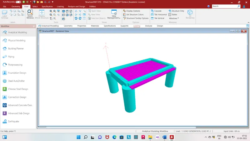
Week 8 Challenge
Aim: To calculate the centrifugal load of the bridge and apply in the staad pro. and perform structural analysis.
Given data:
Span length = 12m
Width of carriage way = 7m
Live load = 70R tracked vehicle
Speed of vehicle = 75 km/hr
Radius of curvature = 3m
Theory:
The moving of a vehicle in a curve produces an outward pushing force from the bridge which exerts loads on the structural elements of the bridge called as the centrifugal loads.
Calculation:
C = W/127R
Where
W is the live loads (tons)
V is the velocity (km/hr)
R is the radius of curvature (m)
Live load W = 70kN
Centrifugal force = W/127R
= 70*75*75/127*3
= 1033 kN
Insert two node with coordinate of (0,0,0) and (12,0,0).
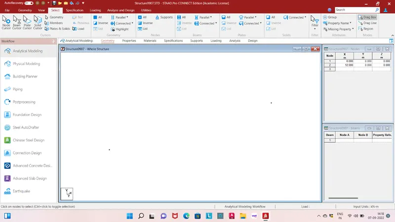
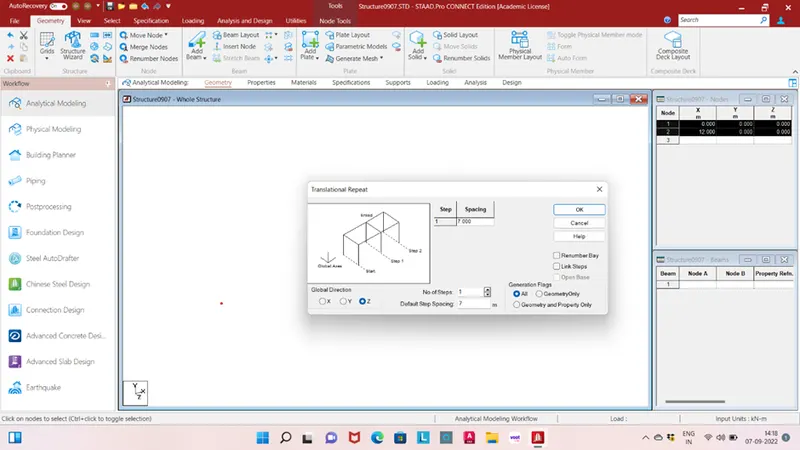
Translation repeat in Z direction spacing 7m no. of step one.
Add beam with connected all nodes.
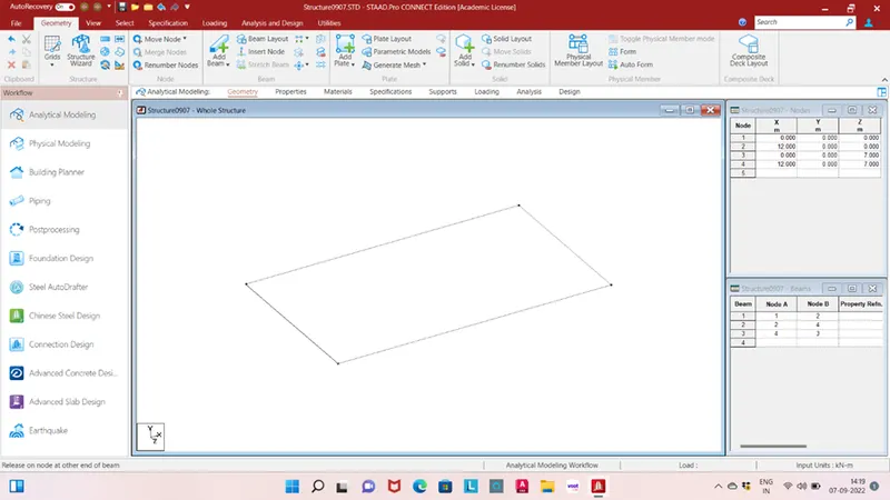
Translation repeat in Y direction with spacing of -5m no. of steps 1.
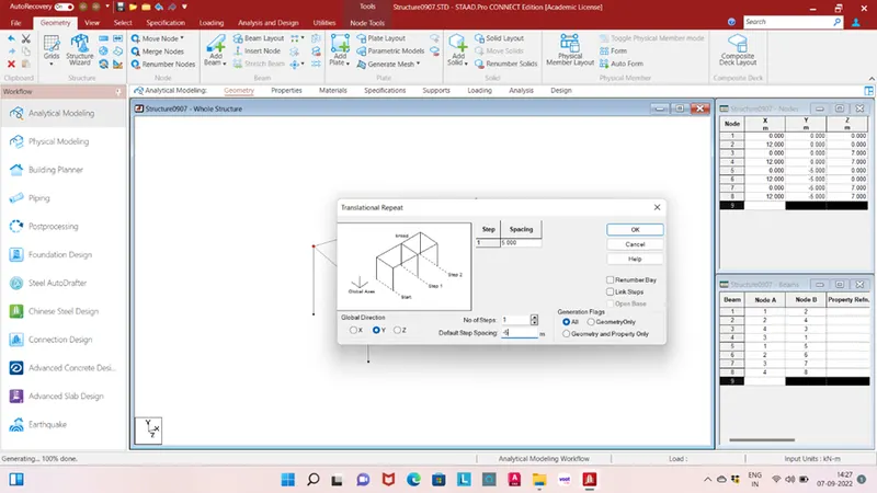
Translation repeat in X direction with spacing of 0.5m no. of steps 1 for add a plate.
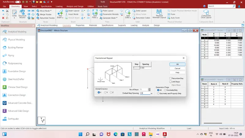
Translation repeat in Z direction with spacing of -0.5m no. of steps 1 for add a plate.
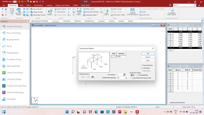
Translation repeat in Z direction with spacing of 0.5m no. of steps 16 for add a deck slab.
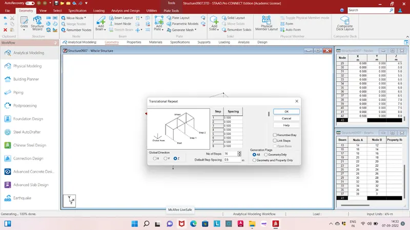
Translation repeat in Z direction with spacing of -0.5m no. of steps 1 for add a deck slab.
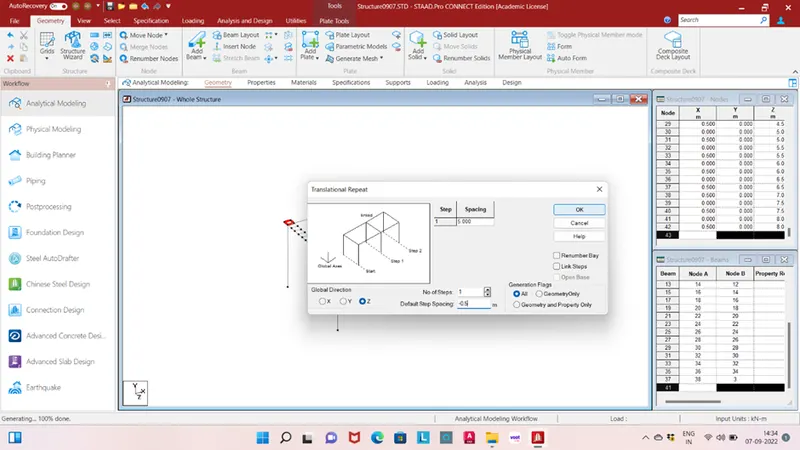
Translation repeat in X direction with spacing of 0.5m no. of steps 23 for add a deck slab.
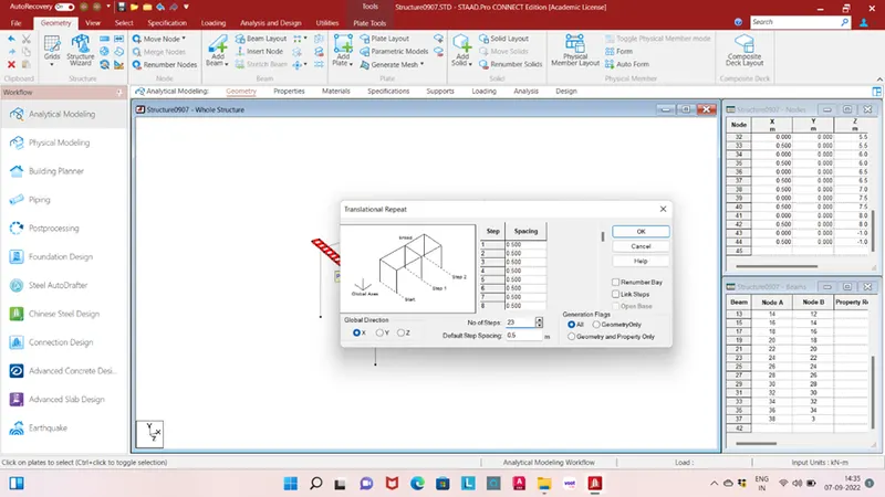
Add fixed support in foundation.
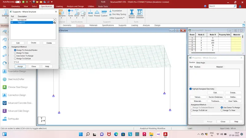
Section details of beam depth 1.2m and width 0.7m material concrete.
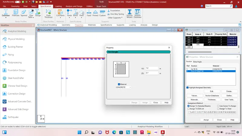
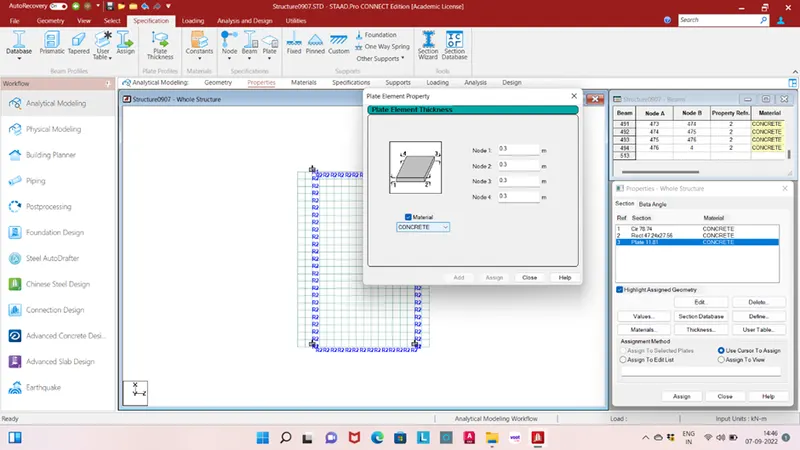
Section detail of deck slab thickness of plate is 0.3m material concrete.
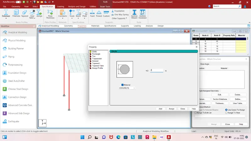
Section detail of pier with diameter 2m material concrete.
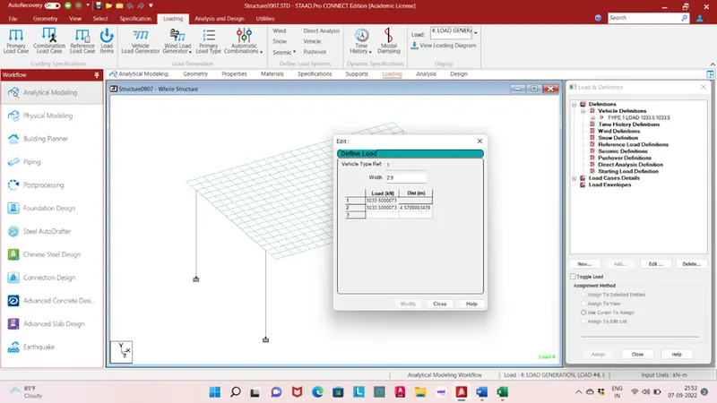
Go to the loading and add a load in vehicle definition two 1033kN load apply with distance of 4.57 and width 2.9.
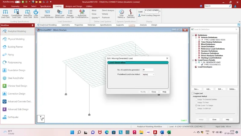
Go to the load cases details and add load generation
- of load generated = total length/ Length of per increment
= 12/0.5
= 24
Add load generation type initial position of load (0,0,6) load increment in X direction 0.5.
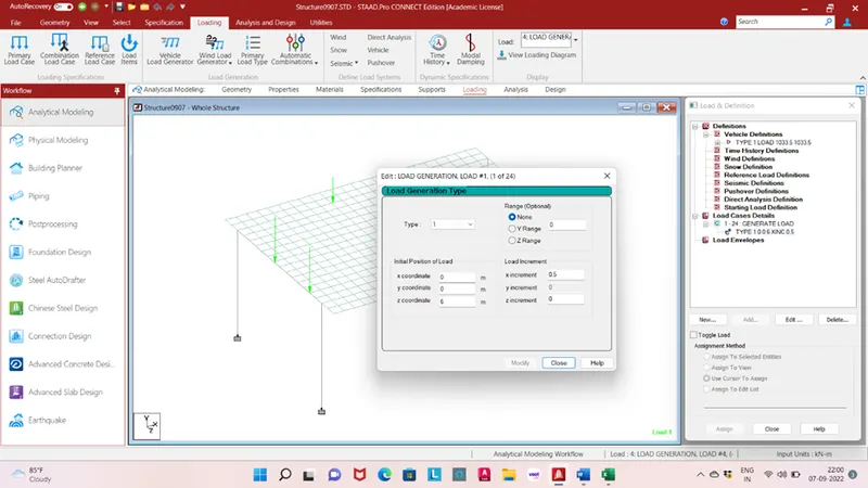
Go to analysis and design and run analysis.
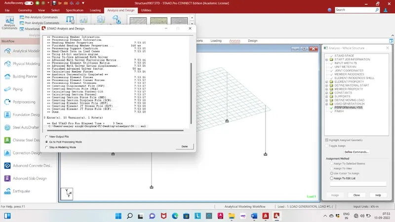
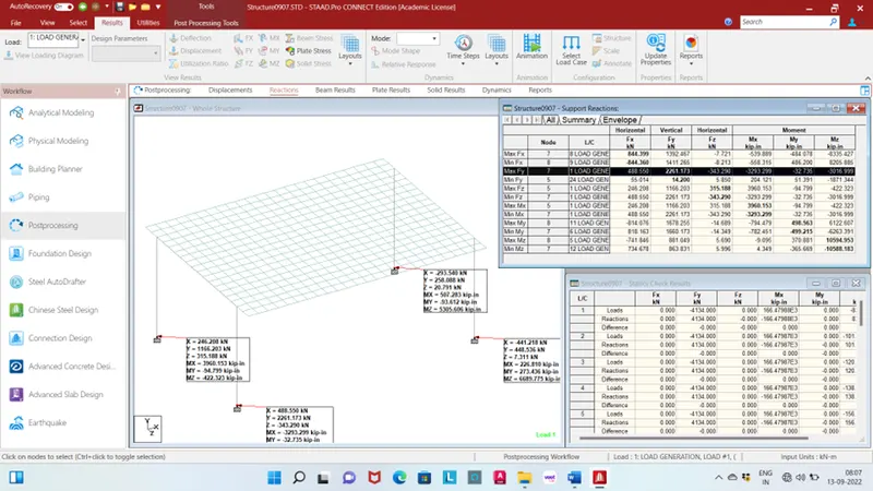
Reaction: support reaction min. and max. Fx, Fy, Fz, Mx, My and Mz
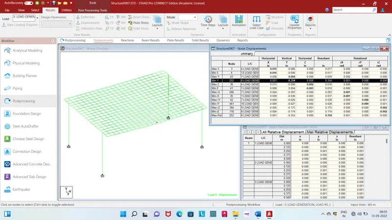
Displacement:
Beam:
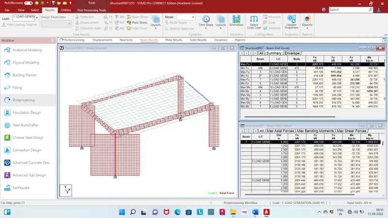
Maximum shear force in X Direction is 2261.173kN for beam no. 7 load case no. 1 live load.
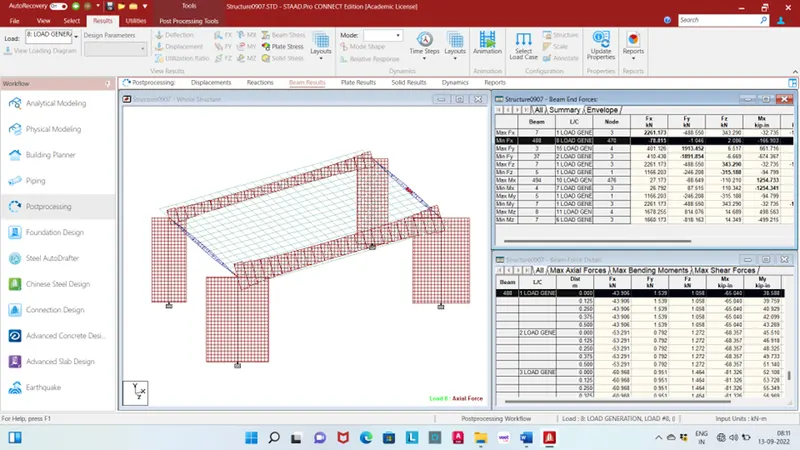
Minimum shear force in X Direction is -78.815kN for beam no. 488 load case no. 8 live load.
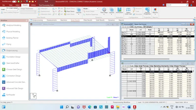
Maximum shear force in Y Direction is 1913.452kN for beam no. 3 load case no. 15 live load.
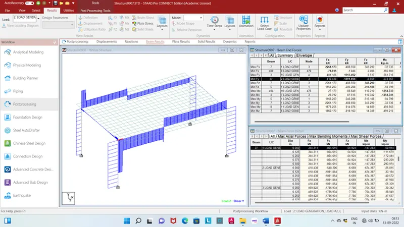
Minimum shear force in Y Direction is -1891.854kN for beam no. 37 load case no. 2 live load.
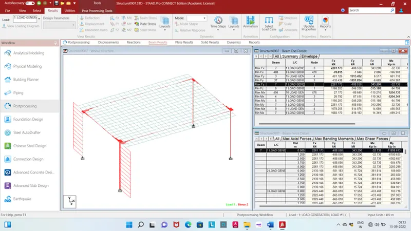
Maximum and minimum shear force in Z Direction is 343.290 and -315.188 for beam no.7 respectively load case no. 1 live load.
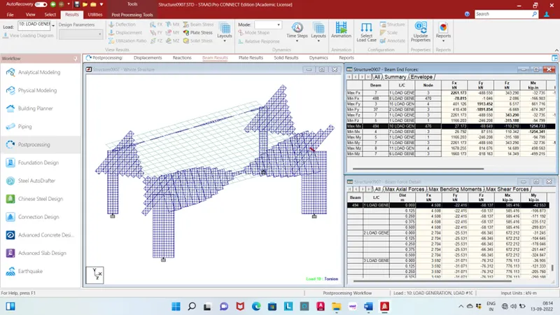
Maximum bending in X Direction is 1254.733kip-in for beam no. 494 load case no. 10 live load.
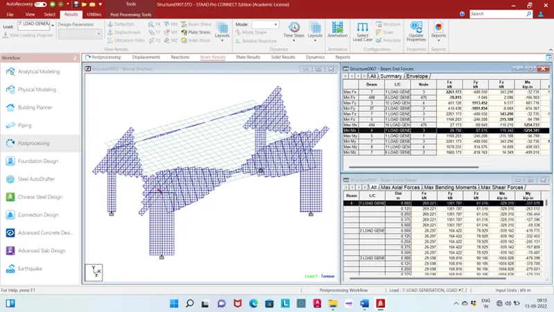
Minimum bending in X Direction is -1254.341kip-in for beam no. 4 load case no. 7 live load.
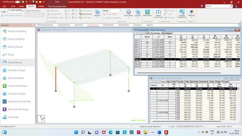
Maximum and minimum bending in Y Direction is 9988.102kip-in and -11898.613kip-in for beam no. 5 respectively load case no. 1 live load.
maximum bending in Z Direction is 29903kip-in for beam no. 8 load case no. 11 live load.
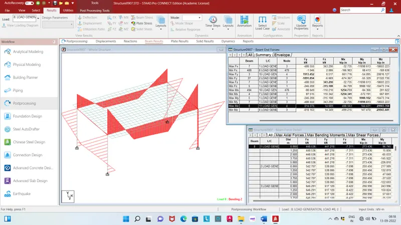
Minimum bending in Z Direction is -29943kip-in for beam no. 7 load case no. 6 live load.
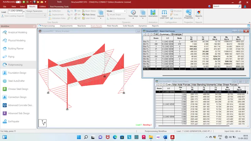
Plate:
Maximum plate bending in X direction is 8.501kip-in/in for plate no. 38 respectively load case no 1 live load.
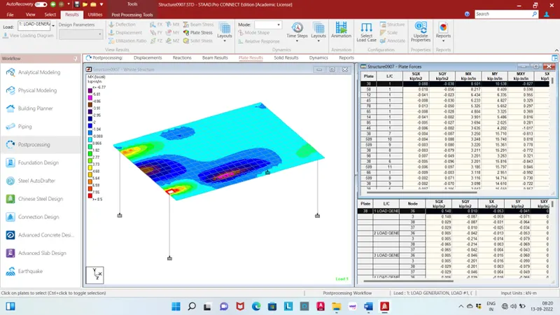
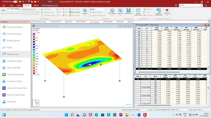
Minimum plate bending in X direction is -7.670kip-in/in for plate no. 258 respectively load case no 12 live load.
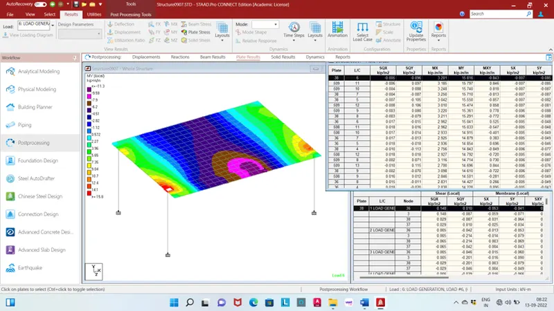
Maximum plate bending in Y direction is 15.816kip-in/in for plate no. 38 respectively load case no 6 live load.
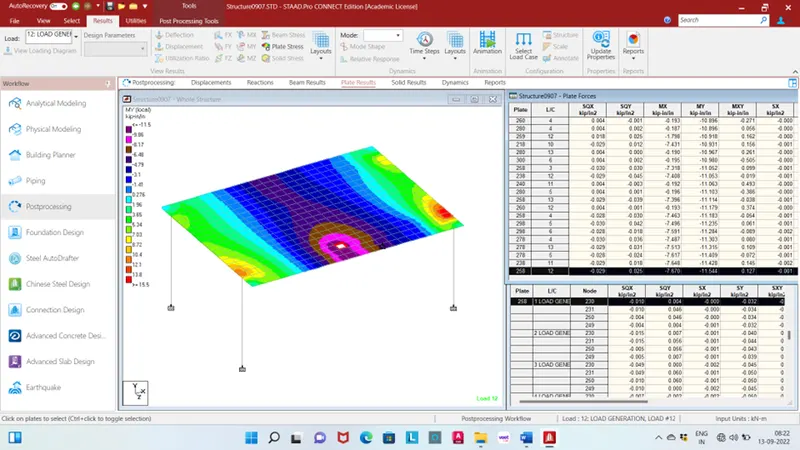
Minimum plate bending in Y direction is -11.544kip-in/in for plate no. 258 respectively load case no 12 live load.
3D view: