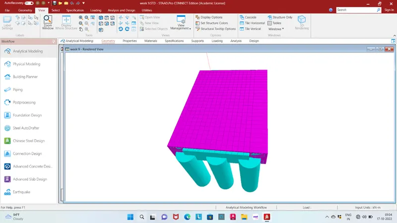
Week 9 Challenge
Aim: To calculate the wave load on the superstructure and apply in the staad pro. and perform structural analysis.
Given data:
Span of the bridge = 12m
Width of deck slab = 9m
Thickness of deck slab = 2m
Maximum crest elevation = 3m
Height of I girder = 1.7m
Width of top and bottom flange = 2.5m
Thickness of flange and web = 0.5m
Constant r =5
Cva = 3
Storm elevation is 8.5m
Cr = 0.4
Number of girders supporting bridge deck N=3
Theory:
Waves are caused by a disturbance of the water surface. They develop due to disturbance like wind boat or ship wakes or other forces such as underwater land slides due to earthquakes. When the wind blow on the sea, waves occur according to the intensity of the wind and generate a force on the any bridge substructure like piers and abutments.
Calculation:
Maximum crest = 3m
∆ = - Centroid of I girder
= 3-(2.5/2)
=1.75m
∆ = - Elevation of bottom deck
=3-2.2
= 0.8m
Number of girders supporting bridge deck N=3
Vertical load, Fv = r X ∆ X
= 5 X 0.8 X (9 X 2.5/2)
= 45 kN
Horizontal load, Fh = r X ∆ X
= 10 X 1.75 X (12 X 3.7)
= 777 kN
Max. vertical load Fv max. = Cva x Fv
= 3 X 45
= 135 kN
Max. horizontal load Fh max. = (1 + Cr(N-1) Cva X Fh)
= (1 + 0.4(3-1) X 3 X 777)
= 4195.8 kN
Insert two nodes with coordinate of (0,0,0) and (0,0,12).
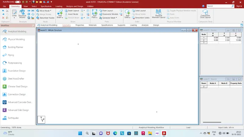
Add beam with connected two nodes
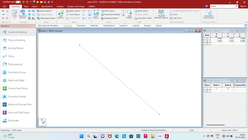
Translation repeat in X direction with spacing 3m no. of nodes 2
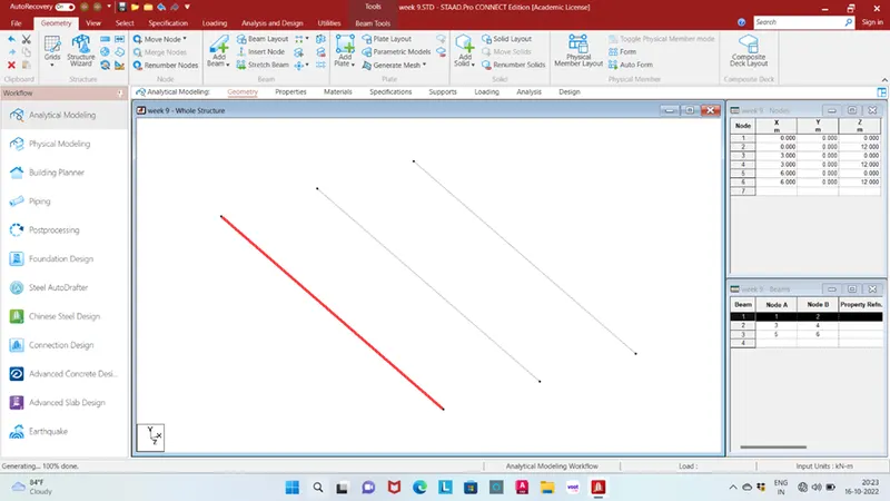
Translation repeat for points in X and Z direction both spacing of 0.5m no. of steps 1 both side
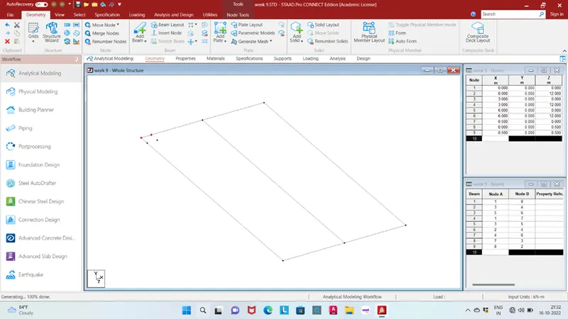
Add plate for deck slab using Translation repeat in X,Z direction spacing 0.5 no. of steps 23 in Z direction and 17 in X direction
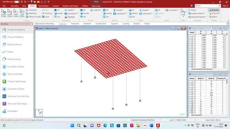
Translation repeat for add pier with span 7m no. of steps 1
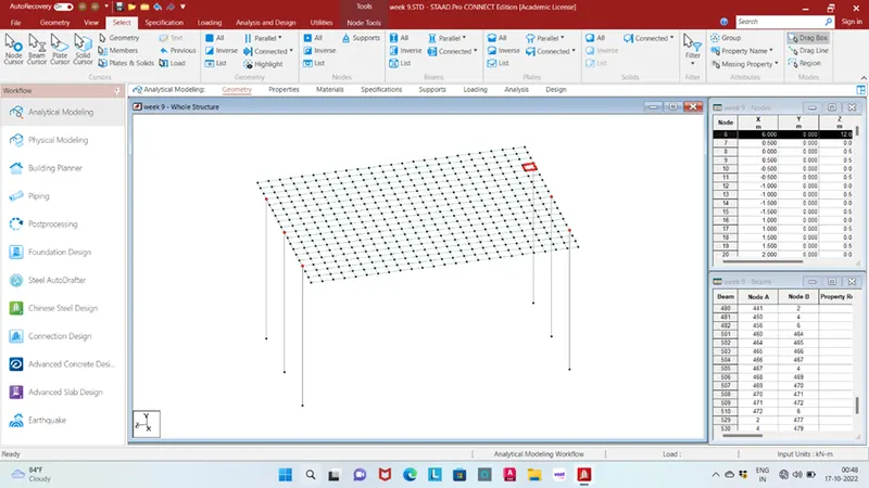
Add fixed support in bottom of pier
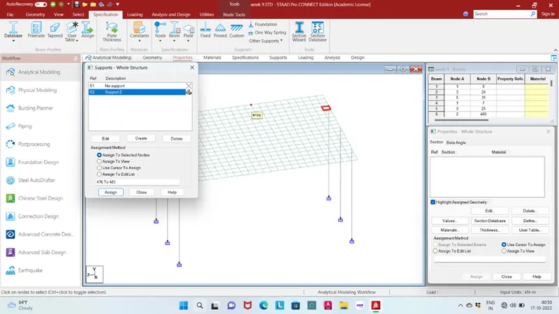
Section detail of main I girder as per given value
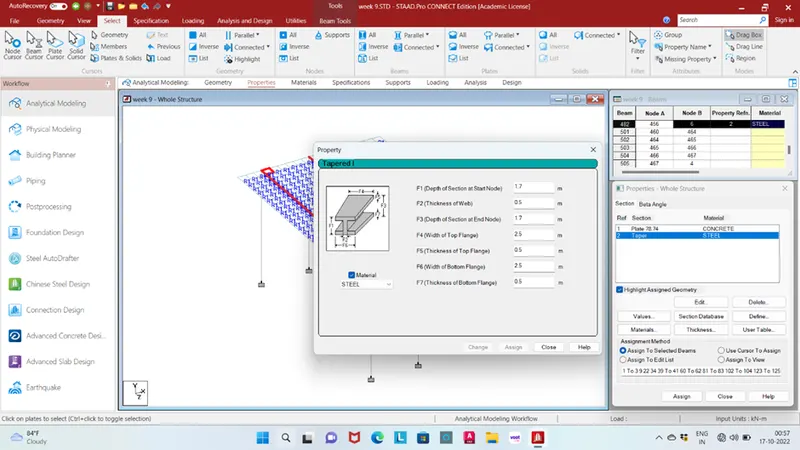
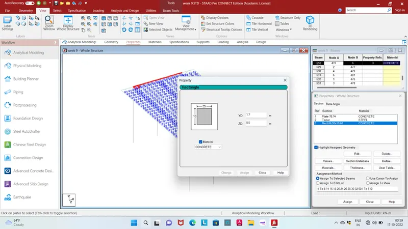
Section detail of cross girder with height of 1.7m and depth of 0.5m
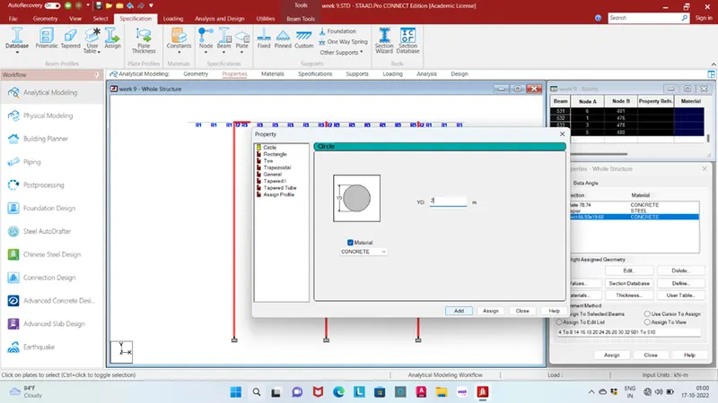
Section detail of pier with diameter of 2m
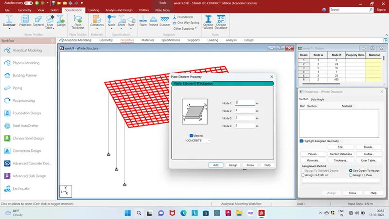
Section detail of deck slab with thickness of 2m
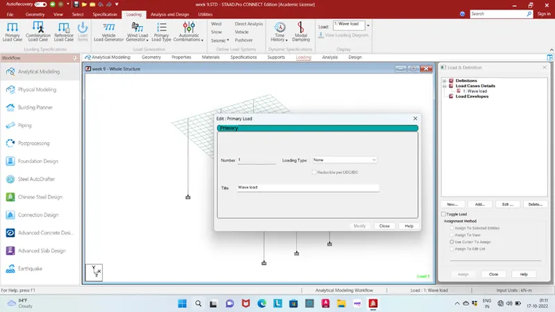
Go to load case details and add wind load
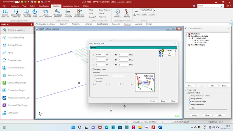
Add horizontal load with value of 4195.8kN
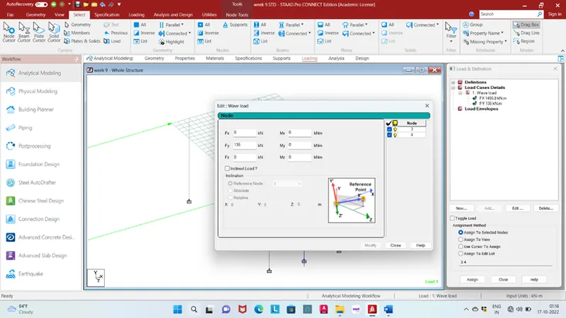
Add vertical load value of 135kN
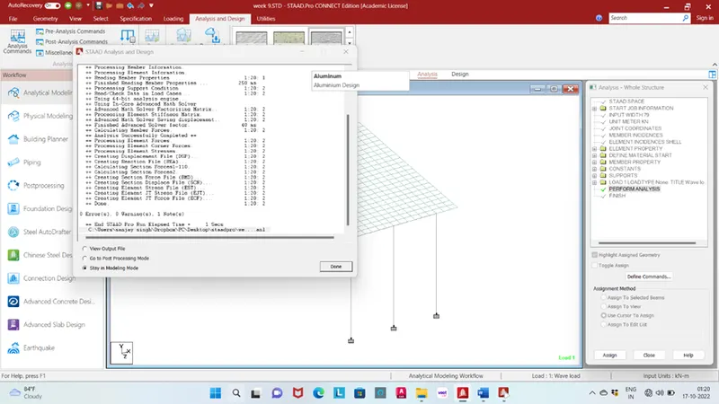
Go to run analysis
Result:
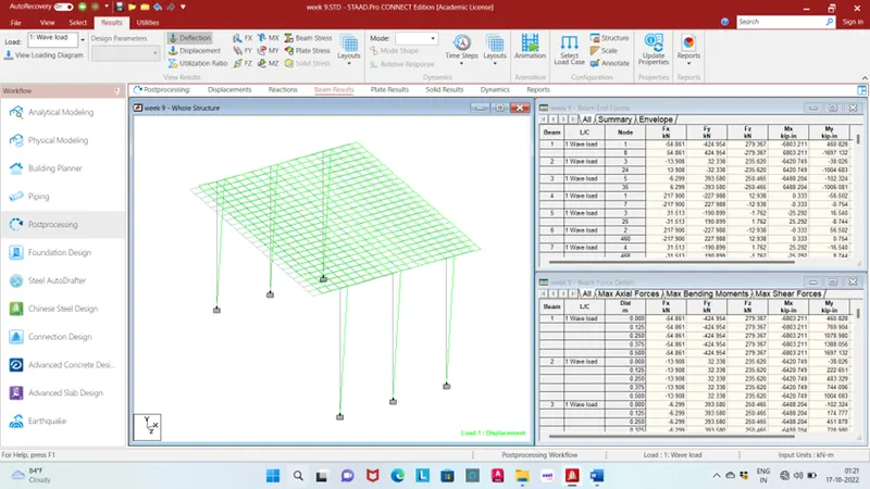
Deflection
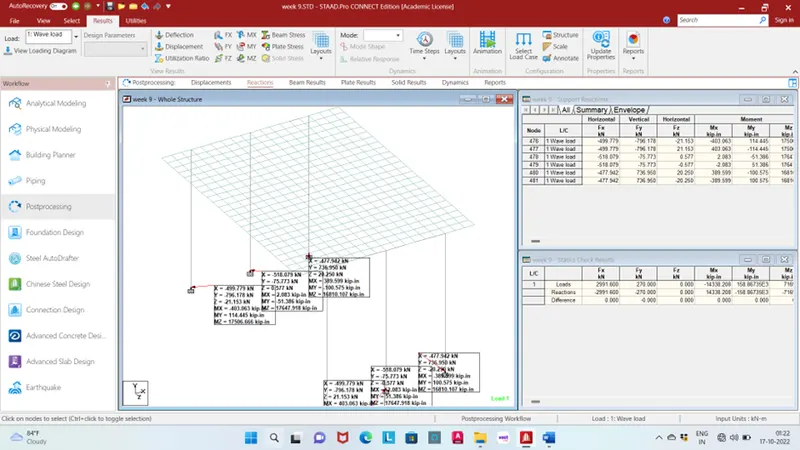
Reaction
Beam:
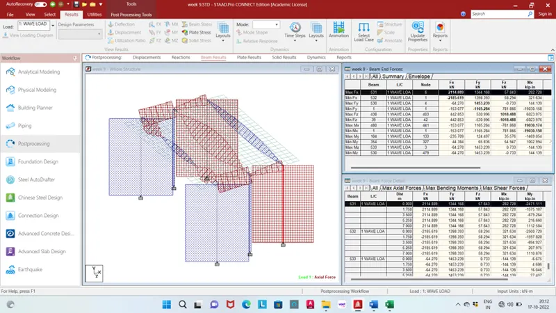
Maximum and minimum shear force in X Direction is 2114.889kN for beam no. 531 and -2185.619kN for beam no. 532 load case no. 1 wave load
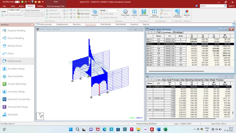
Maximum and minimum shear force in Y Direction is 1453.239kN for beam no. 530 and -1165.284kN for beam no. 1 load case no. 1 wave load
Maximum and minimum shear force in Z Direction is 1018.488kN for beam no. 438 and -1018.488kN for beam no. 39 load case no. 1 wave load
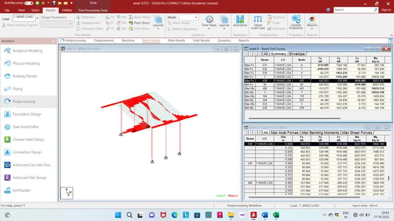
Maximum and minimum bending moment in X Direction is 19030.174kip-in for beam no. 480 and -19030.158 kip-in for beam no. 1 load case no. 1 wave load

Maximum and minimum bending moment in Y Direction is 7059.889kip-in for beam no. 104 and -10659.426 kip-in for beam no. 354 load case no. 1 wave load
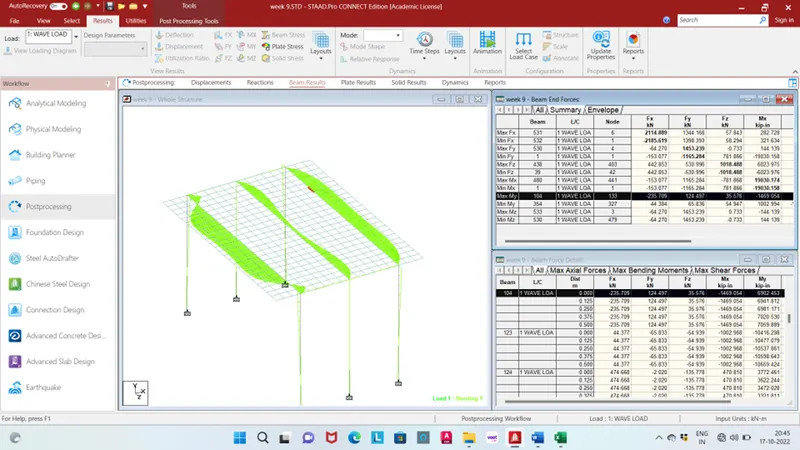
Maximum and minimum bending moment in Z Direction is 40532.492kip-in for beam no. 533 and -49503.363 kip-in for beam no. 530 load case no. 1 wave load
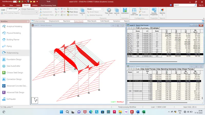
Plate:
Maximum plate bending in X direction is 47.731kip-in/in for plate no. 525 respectively load case no 1 wave load.
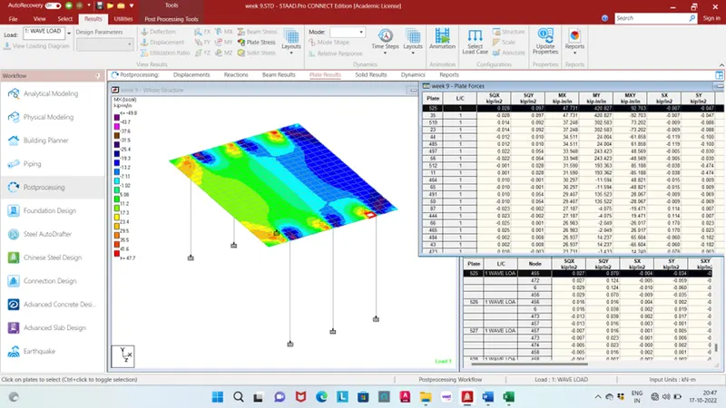
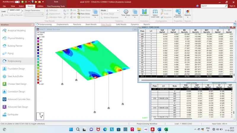
Minimum plate bending in X direction is -49.763kip-in/in for plate no. 511 respectively load case no 1 wave load.
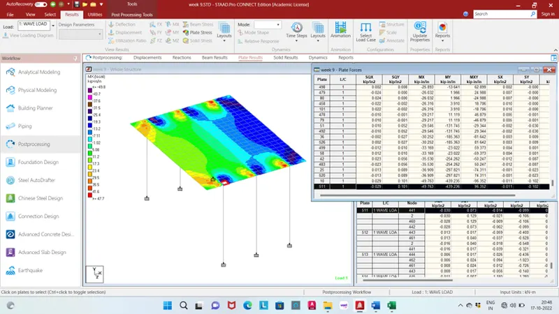
Maximum plate bending in Y direction is 420.827kip-in/in for plate no. 525 respectively load case no 1 wave load.
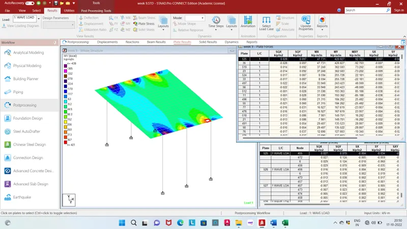
Minimum plate bending in Y direction is -439.236kip-in/in for plate no. 511 respectively load case no 1 wave load.
3D