Battery characteristics using drive cycle
AIM: Simulate generic battery model charge-discharge using UDDS data.
objective: The question can be divided into two parts where the first part is to model the battery and the second part is to analyze the charge, /discharge characteristics for a specific drive cycle.
1.Create a current profile sheet
2.Import the data using an excel file to signal builder block
3.Model the battery with supporting element blocks from the library browser
4.Simulate it and comment on results
Current profile sheet:
https://docs.google.com/spreadsheets/d/1nyjzTNEpkc7tgAMRg1H-_ZxRD4-54N-q/edit#gid=1816926825
Import the data using an excel file to signal builder block:
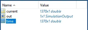
1) made the Array in workspace having the time value and current value which are in the datasheet.
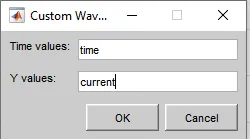
2) Value from the datasheet import in the signal builder by using the custom function.
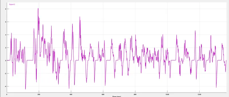
Signal:
Model the battery with supporting element blocks from the library browser:
1) Take the battery block, Controlled current source, BUS, Scope.
2) Made the connection :
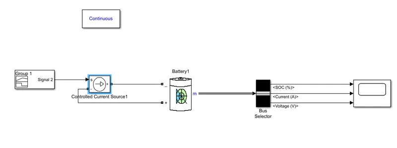
In the above model following block used:
Signal Builder :
The Signal Builder block allows you to create interchangeable groups of piecewise linear signal sources and use them in a model. You can quickly switch the signal groups into and out of a model to facilitate testing. In the Signal Builder window, create signals and define the output waveforms. To open the window, double-click the block.
Controlled current source:
Converts the Simulink input signal into an equivalent current source. The generated current is driven by the input signal of the block.
Battery:
The Battery block implements a generic dynamic model that represents the most popular types of rechargeable batteries.
This figure shows the equivalent circuit that the block models.
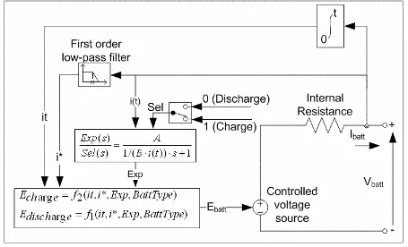
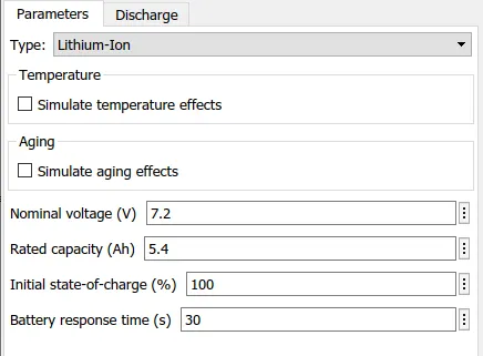
Battery parameters:
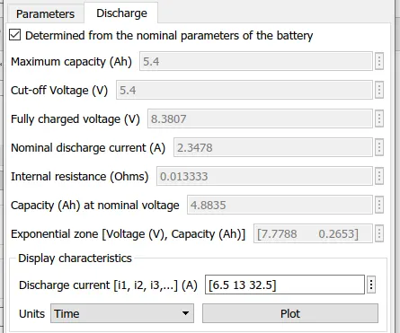
Discharge parameters:
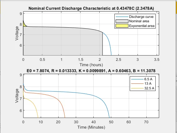
Discharge characteristic:
Bus Selector:
This block accepts a bus as input which can be created from a Bus Creator, Bus Selector, or a block that defines its output using a bus object. The left list box shows the elements in the input bus. Use the Select button to select the output elements. The right Listbox shows the selections. Use the Up, Down, or Remove button to reorder the selections. Check 'Output as virtual bus' to output a single bus.
Scope:
Display signals generated during simulation
Simulate it and comment on results:
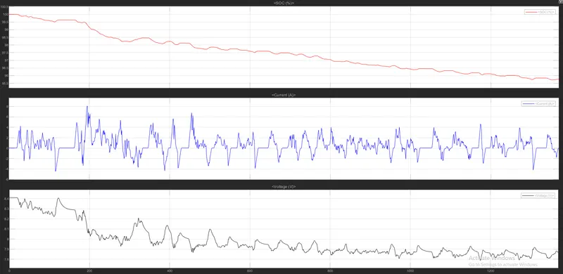
Simulate the model and run the model to get the SOC of battery, Current, Volage, of battery for UDDS drive cycle. Simulation time is same as the drive cycle that is 1369 sec.
Result:
Comment:
As we saw in the Above graph we got the SOC of the battery, Current Followed by the battery as it is in drive cycle, the voltage of the battery how it discharges and gets a charge, and at the end remaining voltage from fully charged voltage that is 8.38.
Max current: 8.1.
SOC:95.75.
Voltage remaining: 7.86.