Week-7 Challenge: DC Motor Control
Q1.Run MATLAB demo ‘Speed control of a DC motor using BJT H-bridge’. Modify the model such that the armature current doesn’t shoot up when the motor changes direction from forward to reverse.
ANS:
AIM: MODIFY THE MODEL SUCH THAT THE ARMATURE CURRENT DOESNT SHOOT UP WHEN THE MOTOR CHANGES DIRECTION FROM FORWARD TO REVERSE.
PROCESS:
1) Open the demo model from the help function of matlab.
2) Run the model with the default parameters and get the result.
3) Change the parameters to the armature current does not shoot up when the motor changes direction from forward to reverse.
4) Run the model with changed parameters and get the result.
5) Observe the result with both conditions and comment on it.
DESCRIPTION:
Before going directly to the model first we know about BJT and H-bridge.
BJT: Bipolar Junction Transistor
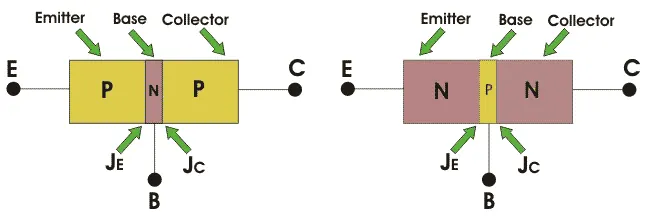
A Bipolar Junction Transistor (also known as a BJT or BJT Transistor) is a three-terminal semiconductor device consisting of two p-n junctions that are able to amplify or magnify a signal. It is a current controlled device. The three terminals of the BJT are the base, the collector, and the emitter. A BJT is a type of transiter that uses both electrons and holes as charge carriers.
There are two types of bipolar junction transistors – NPN transistor and PNP transistor. A diagram of these two types of bipolar junction transistors is given below.
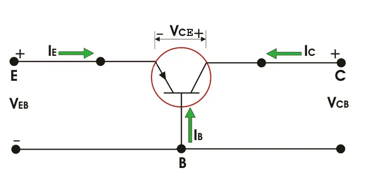
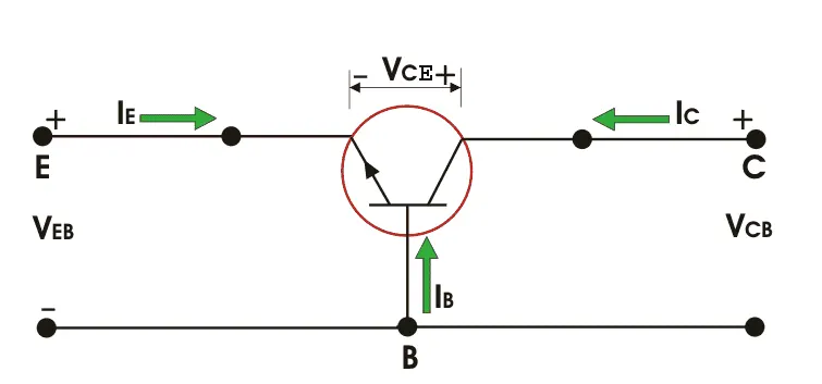
SYMBOLS OF BJT:
PNP Transistor:
NPN transistor:
H-Bridge:
An H-bridge is a simple circuit that lets you control a DC motor to go backward or forward.
H-Bridge concept
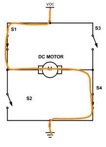
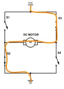
Here’s the concept of the H-bridge:
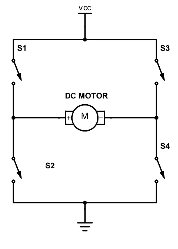
A DC motor spins either backward or forward, depending on how you connect the plus and the minus.
If you close switches 1 and 4, you have plus connected to the left side of the motor and minus to the other side. And the motor will start spinning in one direction.
If you instead close switch 2 and 3, you have plus connected to the right side and minus to the left side. And the motor spins in the opposite direction.
Speed control of a DC motor using BJT H-bridge matlab model:
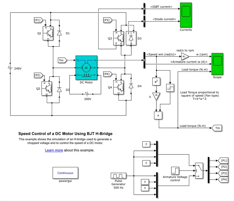
Model Description- The Bipolar Junction Transistor (BJT) when used for power switching applications, operates as an IGBT. When it is conducting (BJT operating in the saturated region), a forward voltage Vf is developed between collector and emitter (in the range of 1 V). Therefore, the IGBT block can be used to model the BJT device.
The IGBT block does not simulate the gate current controlling the BJT or IGBT. The switch is controlled by a Simulink® signal (1/0). The DC motor uses the preset model (5 HP 24V 1750 rpm). It simulates a fan type load (where Load torque is proportional to the square of speed). The armature means voltage can be varied from 0 to 240 V when the duty cycle (specified in the Pulse Generator block) is varied from 0 to 100%.
The H-bridge consists of four BJT/Diode pairs (BJT simulated by IGBT models). Two transistors are switched simultaneously: Q1 and Q4 or Q2 and Q3. When Q1 and Q4 are fired, a positive voltage is applied to the motor, and diodes D2-D3 operate as free-wheeling diodes when Q1 and Q4 are switched off. When Q2 and Q3 are fired, a negative voltage is applied to the motor and diodes D1-D4 operate as free-wheeling diodes when Q2 and Q3 are switched off.
THE MAIN BLOCKS USED TO BUELD THE MODEL:
1) DC machine: The DC Machine block implements a wound-field or permanent magnet DC machine.
For the wound-field DC machine, access is provided to the field terminals (F+, F−) so that the machine model can be used as a shunt-connected or a series-connected DC machine. The torque applied to the shaft is provided at the Simulink® input TL. The armature circuit (A+, A−) consists of an inductor La and resistor Ra in series with a counter-electromotive force (CEMF) E.
2) IGBT: The IGBT block implements a semiconductor device controllable by the gate signal. Used the make the H-bridge with the help of a diode block.
3) Puls generator: The Pulse Generator block generates square wave pulses at regular intervals. The block waveform parameters, Amplitude, Pulse Width, Period, and Phase delay, determine the shape of the output waveform. Pulse generator with voltage generator and switch is used for pule for the transistor for firing angle .
As mentioned in the process with the help of the help function we open the demo model which is shown above dig, know we run this model and get the result with default parameters and the result is shown below:
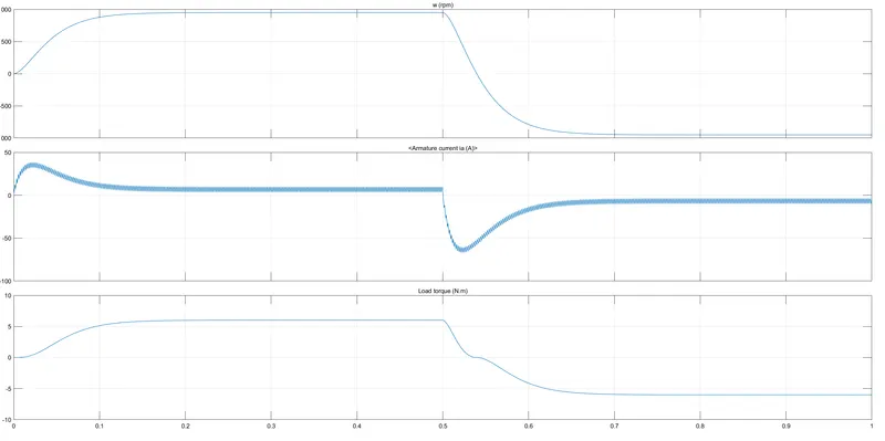
The result shows the speed of the motor, armature current, and load torque with forward and reverse operating mode. As we see the current in the starting of operating mode that is forward and reverse mode current get to shootup and this shoot up current we have to reduce.
which can be done by reducing the firing angle of the transistor so we have to reduce the parameter of the pulse generator
Pulse generator:
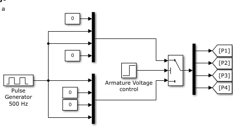
We have to reduce this pulse generator parameter change which is shown below:
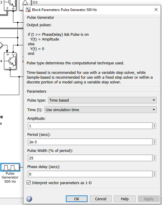
After changing this pulse width we got following result:
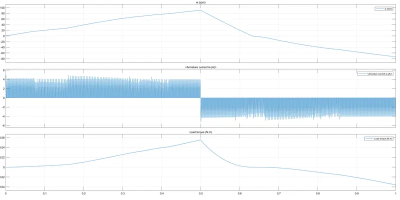
After changing the parameters we get this result this we can see at starting of mode no shootup current.
Q2. Refer to the help section of ‘The Four-Quadrant Chopper DC Drive (DC7) block’. Compare it with the H-bridge model.
ANS:
AIM: Compare the DC7 and H-bridge.
Four-Quadrant chopper:
Type –E chopper or the Fourth-Quadrant Chopper
Type E or the fourth quadrant chopper consists of four semiconductor switches and four diodes arranged in antiparallel. The 4 choppers are numbered according to which quadrant they belong. Their operation will be in each quadrant and the corresponding chopper only be active in its quadrant.
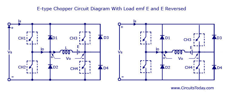
- First Quadrant
During the first quadrant operation, the chopper CH4 will be on. Chopper CH3 will be off and CH1 will be operated. AS the CH1 and CH4 is on the load voltage v0 will be equal to the source voltage Vs and the load current i0 will begin to flow. v0 and i0 will be positive as the first quadrant operation is taking place. As soon as the chopper CH1 is turned off, the positive current freewheels through CH4 and the diode D2. The type E chopper acts as a step-down chopper in the first quadrant.
- Second Quadrant
In this case, the chopper CH2 will be operational and the other three are kept off. As CH2 is on negative current will starts flowing through the inductor L. CH2, E, and D4. Energy is stored in the inductor L as the chopper CH2 is on. When CH2 is off the current will be fed back to the source through the diodes D1 and D4. Here (E+L.di/dt) will be more than the source voltage Vs. In the second quadrant the chopper will act as a step-up chopper as the power is fed back from the load to the source.
- Third Quadrant
In the third quadrant operation, CH1 will be kept off, CH2 will be on and CH3 is operated. For this quadrant working the polarity of the load should be reversed. As the chopper CH3 is on, the load gets connected to the source Vs and v0 and i0 will be negative and the third quadrant operation will takes place. This chopper acts as a step-down chopper.
- Fourth Quadrant
CH4 will be operated and CH1, CH2 and CH3 will be off. When the chopper CH4 is turned on positive current starts to flow through CH4, D2 ,E and the inductor L will store energy. As the CH4 is turned off the current is feedback to the source through the diodes D2 and D3 , the operation will be in fourth quadrant as the load voltage is negative but the load current is positive. The chopper acts as a step up chopper as the power is fed back from load to source.
Four-Quadrant operation of DC motor:
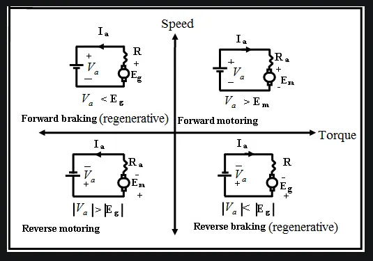
The Four-Quadrant Chopper DC Drive (DC7) block model:
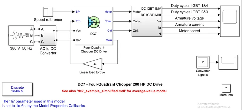
The 200 HP DC motor is separately excited with a constant 150 V DC field voltage source. The armature voltage is provided by an IGBT converter controlled by two PI regulators. The converter is fed by a 515 V DC bus obtained by rectification of a 380 V AC 50 Hz voltage source. In order to limit the DC bus voltage during dynamic braking mode, a braking chopper has been added between the diode rectifier and the DC7 block.
The first regulator is a speed regulator, followed by a current regulator. The speed regulator outputs the armature current reference (in p.u.) used by the current controller in order to obtain the electromagnetic torque needed to reach the desired speed. The speed reference change rate follows acceleration and deceleration ramps in order to avoid sudden reference changes that could cause armature over-current and destabilize the system. The current regulator controls the armature current by computing the appropriate duty ratios of the 5 kHz pulses of the four IGBT devices (Pulse Width Modulation). For proper system behavior, the instantaneous pulse values of IGBT devices 1 and 4 are opposite to those of IGBT devices 2 and 3. This generates the average armature voltage needed to obtain the desired armature current. In order to limit the amplitude of the current oscillations, a smoothing inductance is placed in series with the armature circuit.
the following result is obtained after run above model:
For the Comparison above fig and result is the Four-Quadrant Chopper DC Drive (DC7) block mode and for H-bridge refer to the Q1.
comparison:
| No | Four-Quadrant Chopper DC Drive (DC7) | H-bridge |
| 1. | The main difference is it operates in all four-quadrant operation which is forward motoring, forward braking, reverse motoring, reverse braking. |
In this model, only two-quadrant operations are which is forward motoring and reverse motoring. |
| 2. | Hear chopper mechanism is used for four-quadrant operations | Hear H-bridge is used for two-quadrant operations |
| 3. | AC supply is used and converted to DC with the help of a rectifier. | Direct DC supply is used. |
| 4. | Regeneration can possible. | Regeneration can not possible. |
| 5. | Speed control is possible | Speed control is not possible |
| 6. | We have to give reference speed. | Don't need reference speed. |
Q3. Make a suitable EV model using the DC7 block and make a result report.
ANS:
AIM: Make a suitable EV model using the DC7 block and make a result report.
Process: 1) Open the demo model from the help function of Matlab.
3) Change some blocks to make the proper EV model from the demo model.
3) Make the excel sheet for the Drive cycle of the motor and import it into the new modified model.
4) Run the model with changed parameters, blocks and get the result.
5) Observe the result comment on it.
Description:
EV model using the DC7 bloc:
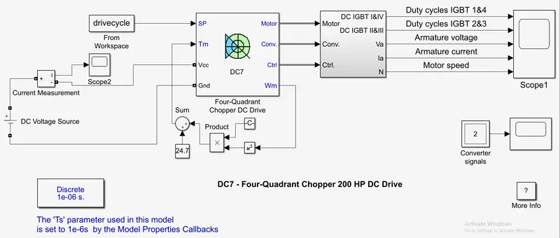
In this model we updated the following block;
1) Input, in the old model they gave the Ac supply but we give DC supply 150v with series with the current measurement block.
current measurement result: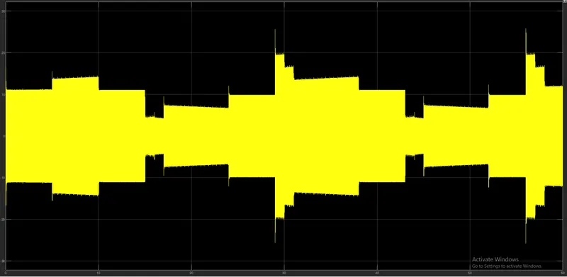
2) liner load torque block is replaced with the load characteristics of DC motor that is `t_r=2407+0.0051*w^2`\
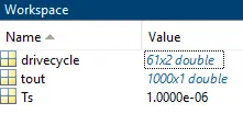
3) made the excel sheet of the Drive cycle for reference.
excel sheet link:
https://docs.google.com/spreadsheets/d/1KNw3a7l0GCQBo8l3f0P83etoabWOiVbvDWKFZOZ7JVo/edit#gid=0
Above EXCEl is imported in the workspace:
Result of this changed model:
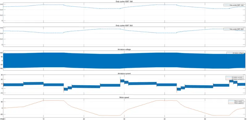
RESULT:
- The duty cycles of IGBT 1 & 4, and 2 & 3 are identical in nature respectively.
- Also, both the pairs are mirror images of each other's duty cycle.
- The amplitude of the armature voltage is approximately equal to the input voltage from the DC source i-e 150 Volts.
- Both the reference and DC7 armature currents are identical to each other, just the amplitude of the DC7 armature current is greater.
- Both the reference and DC7 motor speeds are coinciding with each other and behaving as per the input drive cycle data.