Week 4 - CHT Analysis on Exhaust port
Aim:
To simmulate conjugate heat transfer concept using a exhaust port of an engine. and to understand how heat convection happens around the wall of exhaust pipe.
Introduction:
Given model is a exhaust pipe of a four cylinder engine. we are here by instructed to conduct a hot fluid flow simulation in particular given model. we will do geometrical edits in space claim, meshing, solving by defining boundry conditions, & at last will display the results in cfd post.
we are asked to find Heat tranfer coefficient in the walls. and Ylus number kepts as low as possible.
Detailed steps of simulation will be explained below.
Theory:
Given model is a exhaust port of an engine, where hot exhaust air is sent out from combustion chamber through aluminium pipes. By meshing the given pipe model, we name following parts, inlet, outlet, fluid volume, solid vol. etc and mesh these parts. By giving inflation layer to the to the fluid volume and defining first layer thickness by using wall distance folmula given below. so that we can get solve the model using k-omega model where boundry layer thickness is considered while solving.
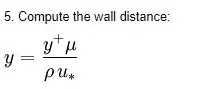
By keeping Wall Yplus bellow 5 we can get accurate results for heat transfer. This can only be achived by calculating first laye thickness using above formula
Applications of CHT:
CHT (Conjucate heat transfer) is a phenomenon gererally happening in daily activities, like heat transfer from fluid to solid or vice versa, eg: while heating a bowl with water.
The study of this concept helps us to desing the material of the solid part and to decide the fluid properties etc.
Major applications are in automobile sector, heat exchangers, dust collectors, boliers, blowers etc.
In this case we study about thr heat transfer through a exhaust pipe of an engine.
PROCEDURE:
Geometry setup:
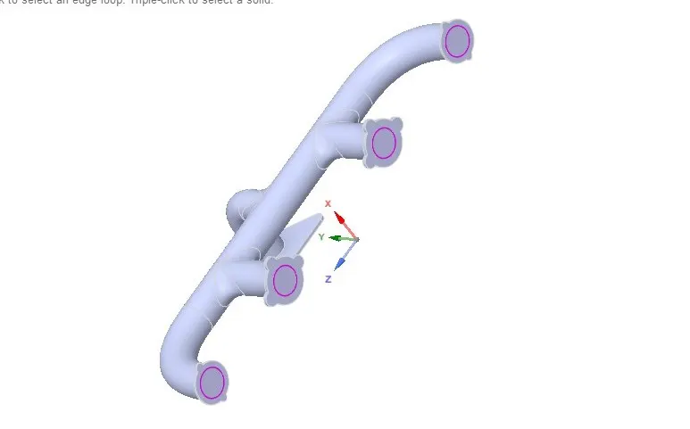
Given model is imported to the spaceclaim where its volumes are defined and topology sharing is enabled. through which information is shared between the volumes and helps in meshing syncronization
Meshing:
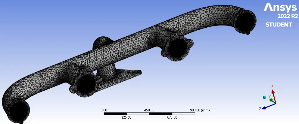
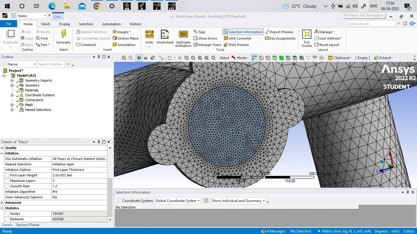
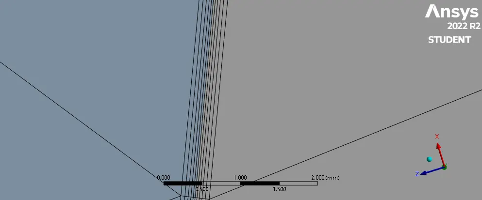
During meshing we define the all inlets, outlets & body of the model. And gave the inner fluid body an inflation layer based on first layer thickness.
Total elements: 425508, First layer thickness: 0.025mm.
Solving:
After meshing model is taken to ansys fluent to solve.
This particular simmulation is done by pressure based, steady state & using k-omega model. so that we can get accurate results.
We define the materials used in both working fluid and solid body.
Working fluid is hot air & solid body is defined as aluminium.
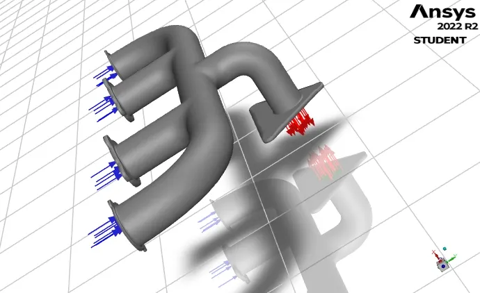
Also we enter the boundry conditions like inlet air speed and temperature. Outer wall heat transfer coefficient ie., 20 W/(m2 K).
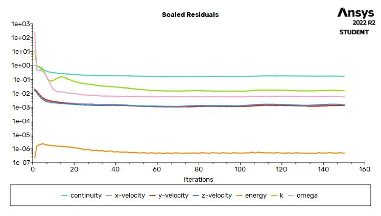
Scaled Resudials:
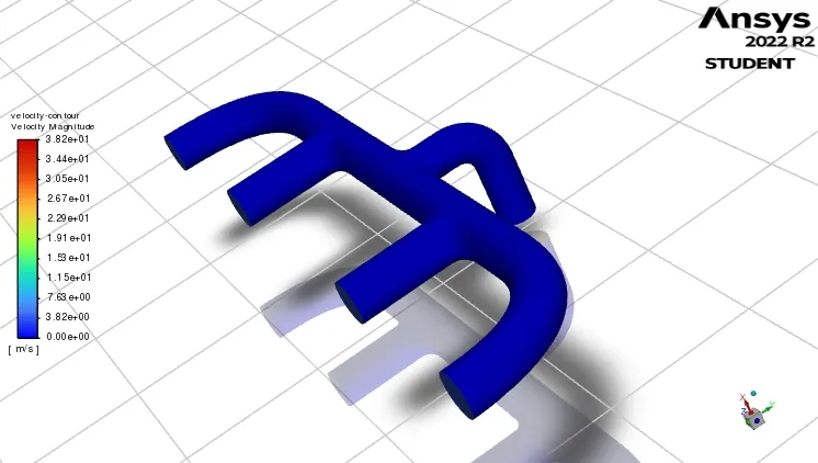
velocity contour:
Static Temperature contour:
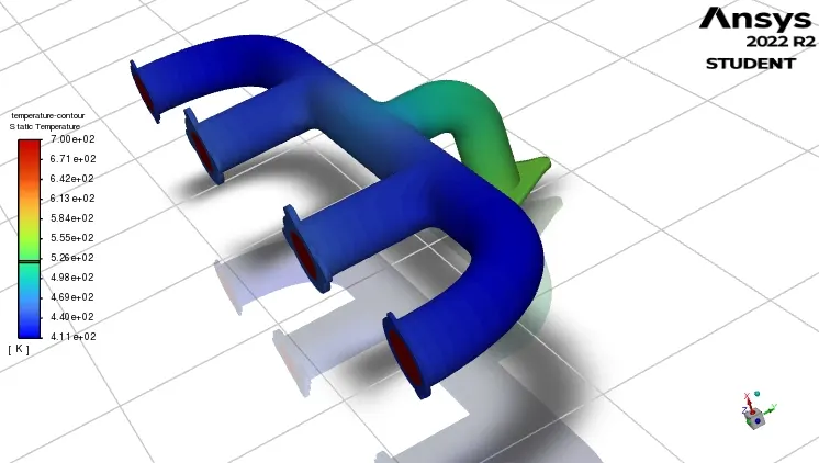
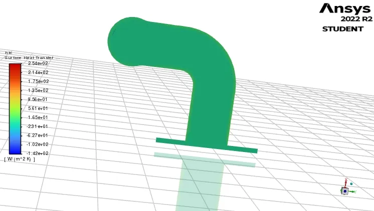
Conjugate heat transfer plot:
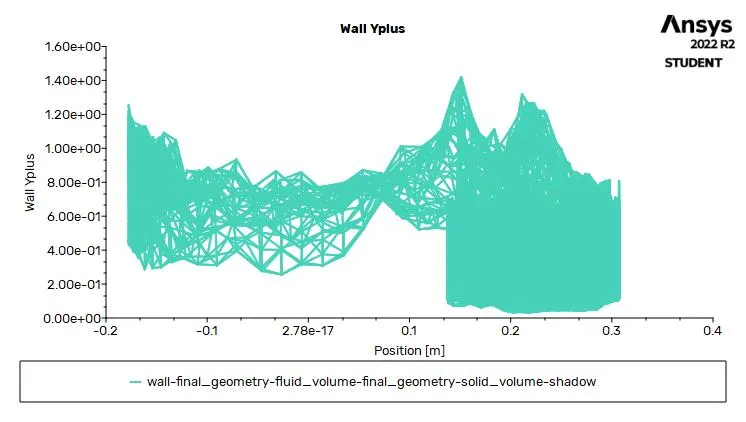
YPLUS WALL Plot:
CFD POST:
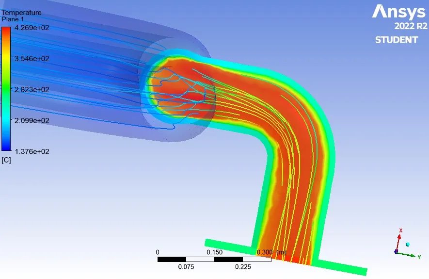
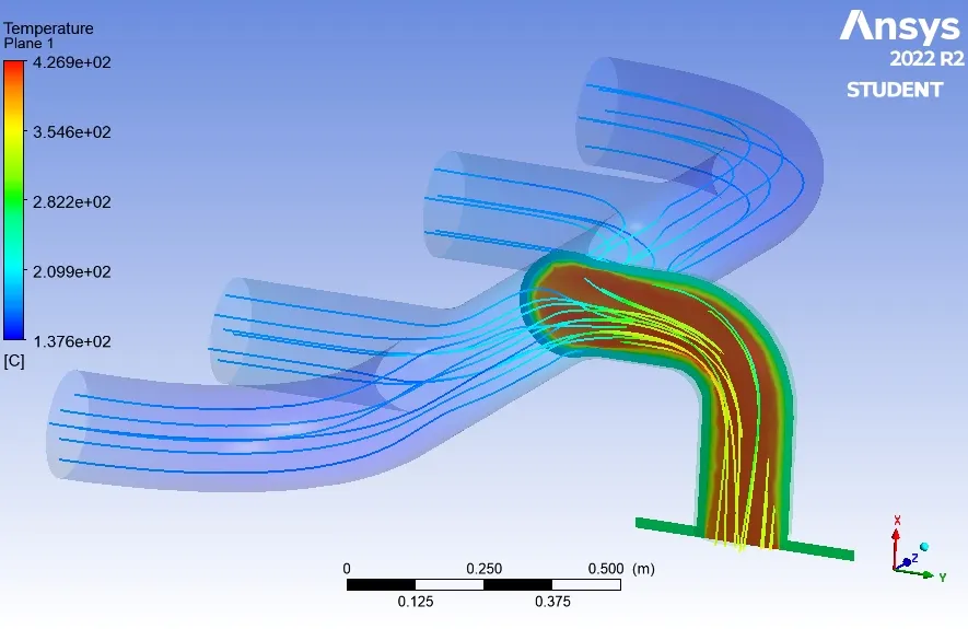
Temperature distribution along wall:
Results:
Given model is simulated perfectly since i was only getting CHT plot on ansys fluent not in CFD Post. only snippets of fluent is attached for CHT.
Since i have got wall yplus less than 2, the results are pretty good.