Week - 4
1. We have to implement a control logic of a “washing machine” using Stateflow as per given sequence:
- If the power supply is available, the system gets activated
- If the Water supply is not available, stop the process & indicate through LED
- Soaking time should be 200s followed by Washing time of 100s.
- Then rinsing happens for next 20s & dryer runs for 50s
After all the processes have completed turn on the finished LED
Here is the Stateflow for the control logic of the washing machine with the given conditions;
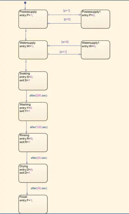
The values 'p' and 'w' is taken as input. If p<1 which means there is no power supply and if p>0 means that the power supply is ON. If P=1 then the process will be continued and if there have the water supply (w>0) then the next process will be activated and if there is no water supply (w<1) the process stops. If W=1, then went to the next process soaking. After 200 seconds of soaking, washing will be started and after 100 seconds of washing rinsing followed drying will be done for 20 and 50 seconds respectively.
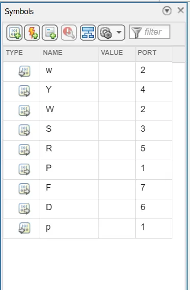
This is the symbol pane of the stateflow; here all values other than p & w are given as output.
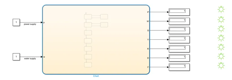
This is the logic control of the washing machine as per the given conditions. I haved used contant blocks and display blocks inorder to give input and shows the output. The LED indicator shows GREEN colour for the succesfull proces. If there is no power supply all indicator will show RED and if there is power supply and no water supply other indicator exclude the power indicator will show RED.
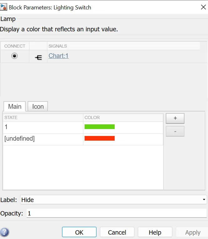
This is the configuration of lighting switch.
2. We have to make a Simulink chart for the “Gear shift” logic as per below conditions:
Speed Range(kmph) Gear
0 to 15 1
16 to 25 2
26 to 40 3
41 to 60 4
Above 61 5
Give speed input while the simulation is running & display the gear number.
Simulink Model:
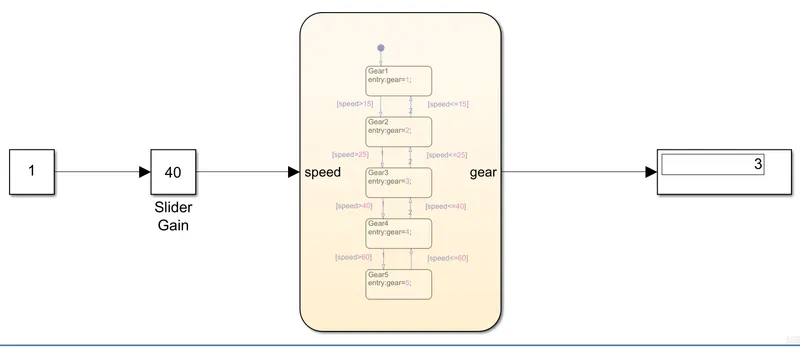
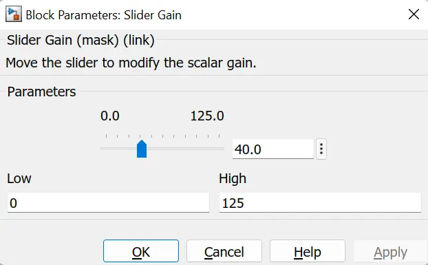
The slider gain block is connected to give the input speed to the system folowed by the constant block. And the slider gain parameter changed to 0 as low and 125 as high. The gear possition will be shown on the display as per the give input speed.
Stateflow:
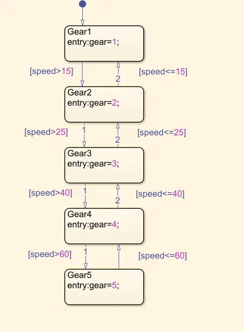
Speed is taken as input and gear as output. The conditions for the gear shift is given to the chart as per the needs.