Week-6 Challenge: EV Drivetrain
1. Which types of power converter circuits are employed in electric and hybrid electric vehicle?
Power Converters
A power converter is an electrical circuit that changes the electric energy from one form into the desired form optimized for the specific load. A converter may do one or more functions and give an output that differs from the input. It is used to increase or decrease the magnitude of the input voltage, invert polarity, or produce several output voltages of either the same polarity with the input, different polarity, or mixed polarities. Power converters are used in Electric / Hybrid Electric vehicles to manipulate the form and magnitude of voltage and current fed from and to the vehicle. There are different types of power converters using in electric and hybrid electric vehicle;
- AC/DC Converter (Rectifier)
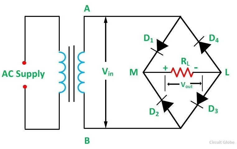
AC to DC converters are one of the most important in power electronics because there are lot of real applications are based on this conversions . The AC to DC conversion process is known as rectification . The rectifier converts AC supply into the DC supply at load end connection. Mainly these converters using in the vehicles for charging application of battery. The output AC supply is converted to DC to charge the battery.
- DC/AC Coverter (Inverter)
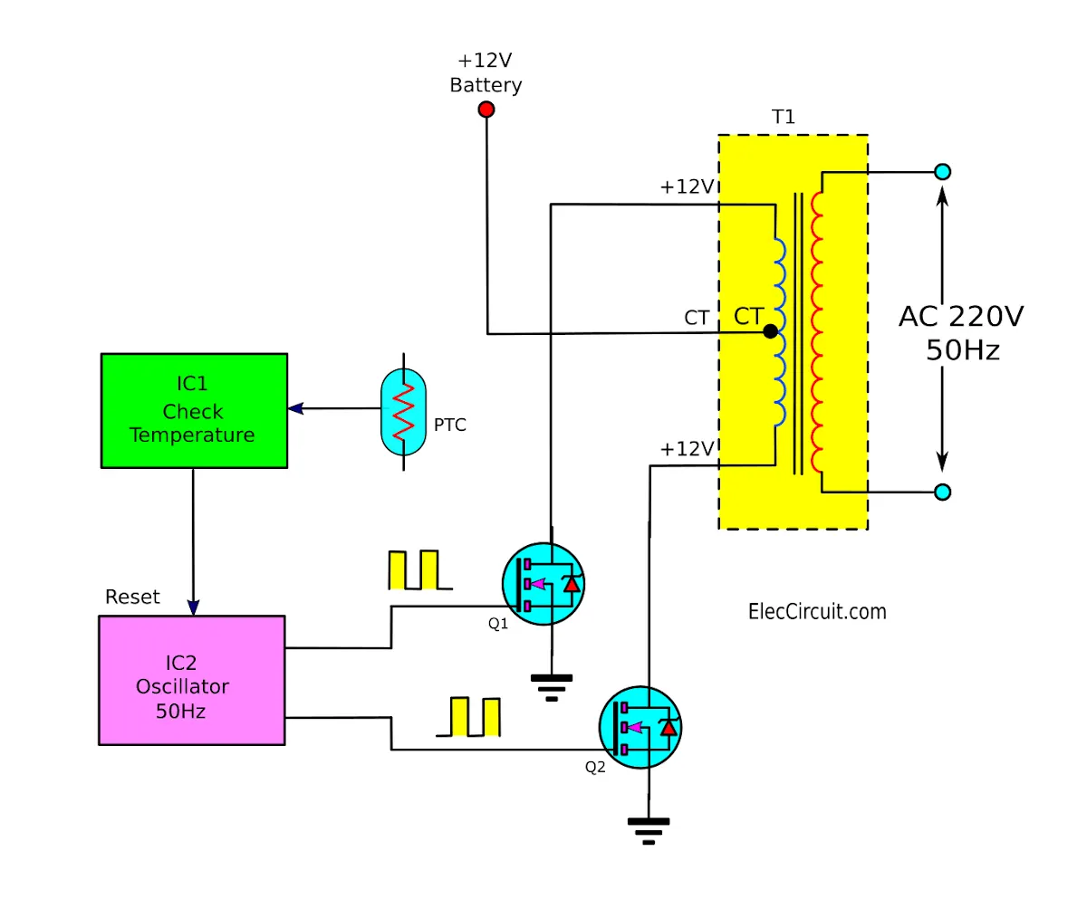
These convert DC voltage into regulated AC voltage . Form and magnitude are regulated . Usually emplyed when an AC motor is used to drive the vehicle . In the case of EVS and HEVS , the battery pack will supply its power to the inverter . The inverter contains a transformer which consists of a primary and secondary winding . The current from the battery is first supplied to the primary winding where the electronic switches will repeatedly reverse the direction of the current to create an AC waveform . This current will return the way it came from . The AC in the primary winding will induce an AC in the secondary winding which then supplies this current to an AC load e.g. the AC traction motor.
- AC/AC Converter
Regulated AC output from AC input . The above converters either increase the magnitude of the output voltage ( boost converters ) or reduce the output voltage ( buck converter ) . This converter can convert from a fixed ac input voltage into variable AC output voltage . The output voltage is controlled by varying firing angles of TRIAC . These types of converters are known as AC voltage regulators.
- DC/DC Converter (Chopper)
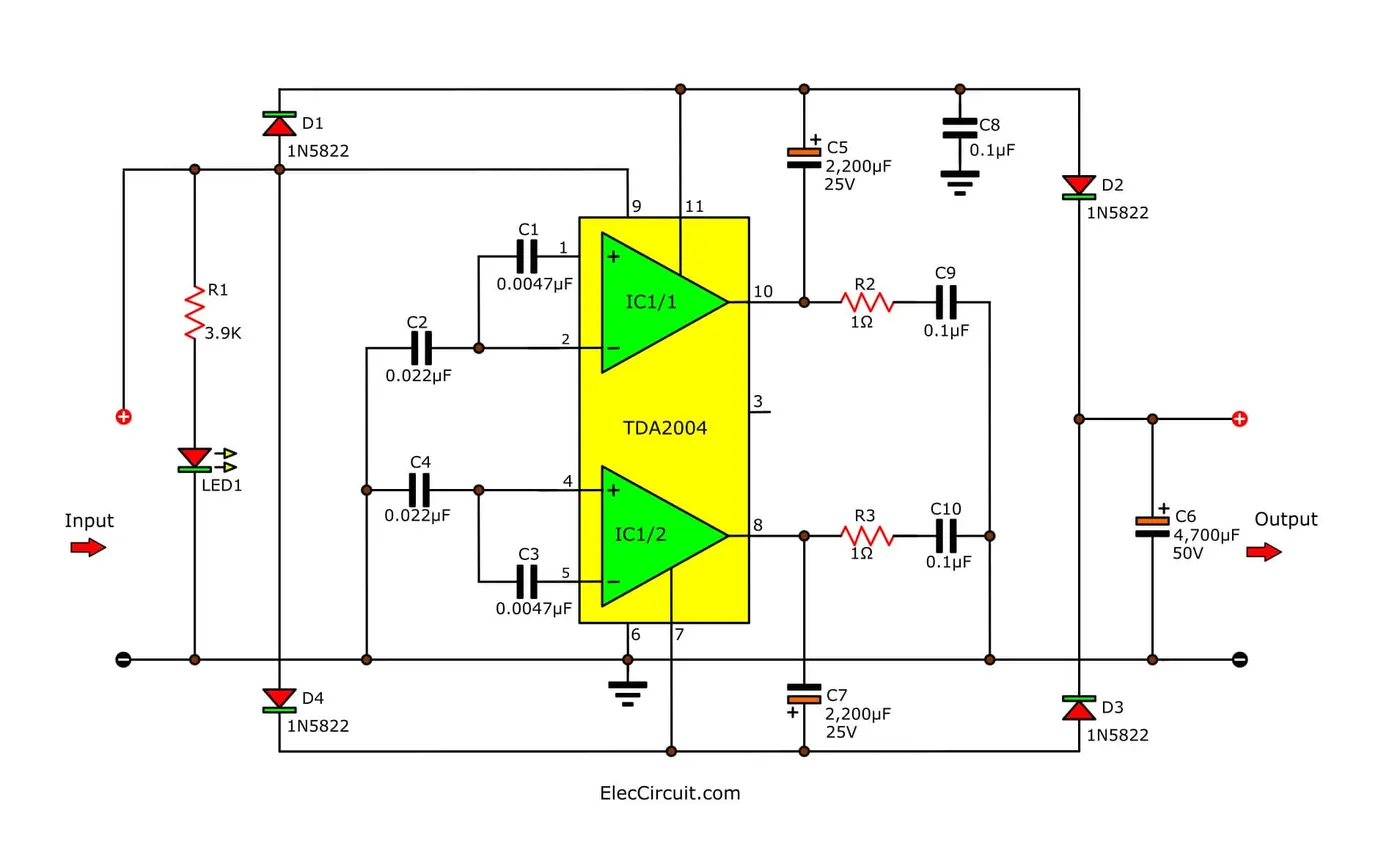
This converts one value of DC voltage into another value of DC voltage ( increase / decrease ) . Th DC / DC converters used in EVS may be for providing low voltage ( 12V or 14V ) for low voltage loads ,boosting the voltage level of the battery such that it matches the level of the DC bus voltage for driving the AC motor inverter, if the traction motor is an AC motor, motor propulsion if the traction motor is a DC motor .
2. An Electric Vehicle's powertrain with 72V battery pack in shown in the diagram below. The duty ratio for acceleration operation is 'd1' and for the braking operation the duty ratio is 'd2'.
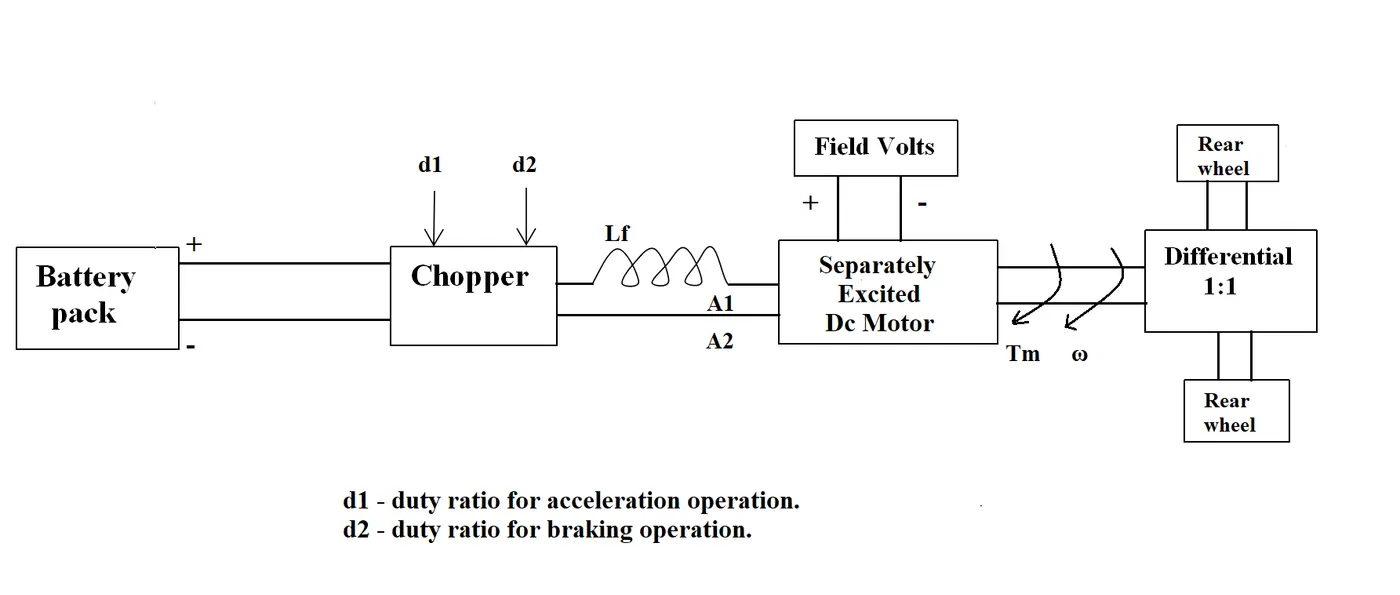
The other parameters of the electric vehicle is given below,
Motor and Controller Parameters:
Rated Armature voltage= 72 V
Rated armature current= 400 A
Ra= 0.5Ω, KΦ= 0.7 Volt second
Chopper Switching frequency= 400 Hz
The vehicle speed-torque characteristics are given by the below equation

What is EV steady state speed if duty cycle is 70%?
Motor and Controller Parameters:
Rated Armature voltage= 72 V
Rated armature current= 400 A
Ra= 0.5Ω, KΦ= 0.7 Volt second
Chopper Switching frequency= 400 Hz
The vehicle speed-torque characteristics are given by the below equation
..........................(1)
We have,
Duty Cycle = 70% = 0.7;
Actual Voltage = 0.7 * 72 =50.4 V
The Torque Equation For Motor is
T = (V*kφ/Ra) - ((kφ)^2/Ra).w
T = (50.4*0.7/0.5) - (0.7^2/0.5) w
T = 70.56 - 0.98 w...........................(2)
From (1) & (2)
24.7 + (0.0051)w^2 = 70.56 - 0.98 w
0.0051 w^2 + 0.98 w - 45.86 = 0
By solving this equation we get 2 values for w
Solving quadratic equation using the formula
w = -b ± √(b² - 4ac)/2a
where,
a = 0.0051
b = 0.98
c = 45.86
Substituting the above values in equation
w = -0.98 ± √ (0.98² -4x 0.0051 x 45.86 ) 2 x 0.0051
w = 38.915 rad/sec & w = -231.072 rad/sec
That is EV Steady State Speed if duty cycle is 70% will be 38.915 rad/sec or 371 RPM
3. Develop a mathematical model of a DC Motor for the below equation using Simulink.
ω= V/Kϕ -Ra/Kϕ^2 .T
Simulink Model:
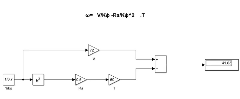
Assuming the values;
V = 72 V
T = 60 Nm
Ra = 0.5 ohm
kφ = 0.7 volt second
Simulink Blocks Used:
- Constant block is used to give the value of 1/kφ
- Square block is used to take square of 1/kφ
- Gain blocks are used to give the values of V,T and Ra
- Subtraction block is used to perform the subtraction
- Display is used to view the value of w
Simulink File: w_equation
4. Refer to the blog on below topic:
Induction Versus DC brushless motors by Wally Rippel, Tesla
Explain in brief about author’s perspective.
In this blog the author Wally Rippel discussed about what are the diffrences and challenges are facing while using DC Brushless motor and Older one Nicola Tesla invented 3 phase induction motor elabratedly . Initially the author comparing this drives with engine by giving one example choosing one best engine type for all the needs is too difficult . Why becuase there is no one best engine type it depends upon the personal requirements price and performance needed . This is also true for a electric drives . From this the author conclude one drive and one engine is not fit for all . And then author compared the Induction motor and Brushless DC motor.
- In the beginning , author describes the dominance of Internal Combustion Engines ( ICE ) in the world of automobile industry and also discuss different types of engines. He explains that all engines were similar and it was up to the user to select according to their requirement. He also speaks about induction motor and brushless DC motors and presents his view that these two technologies will be widely used for the coming years.
- Then he explains the working of both 3 - phase induction motor and a brushless DC motor.
- Now the author has done comparison between these two technologies and stated some advantages and disadvantages of each .
- Induction motor have some advantages like : it has no magnets. The motor has the ability to start under load. No inverter is needed. Some disadvantages of Induction motors are : They cannot operate from DC ; AC is a must. Shaft speed is proportionate to line frequency. Hence , when used with utility power , they are constant speed machines. When operated from utility power , they have limited starting torque and somewhat limited running peak torque capabilities , when compared to DC type machines.
- Brushless DC motor have some advantages like : much less rotor heat is generated with the DC brushless drive. The peak point energy efficiency for a DC brushless drive will typically be a few percentage points higher than for an induction drive. Some disadvantages of Brushless DC motor are : as machine size grows , the magnetic losses increase proportionately and part load efficiency drops. Permanent magnets are expensive and difficult to handle due to very large forces that come into play when anything ferromagnetic gets close to them.
- Finally the author couldn't choose which drive is better than the other but makes it clear that DC brushless drives will likely continue to dominate in the hybrid and coming plug - in hybrid markets , and that induction drives will likely maintain dominance for the high performance pure electrics.