Week -2
1. Simulink model of Doorbell using solenoid block
In the above arrangement, when the switch is closed the electromagnet receives electrical power from the battery and pulls the metal arm to hit the bell producing sound. We have to create a simulink model of doorbell by using solenoid block, where the switch is closed for 2 seconds and then released.
Simulink and Simscape Blocks Used
- Pulse Generator
- Simulink-PS & PS-Simulink Converter
- Switch
- Battery
- Solenoid
- Ideal Translational Motion Sensor
- Electrical Reference
- Mechanical Reference
- Solver Configuration:
- Scope
- Display
Simulink & Simscape Block Design
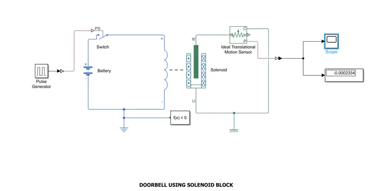
The solenoid is connected with a battery and swicth. A pulse generator is connected to the swith by using a simulink-PS coverter inorder to give input signal to the switch. An ideal translational motion sensor is connected to the solenoid, which provide the position of input signal. The output from the translational sensor is connected to the scope and display by using a PS-simulink converter. A solver configuration is connected to the system which act as a complete equation for the system. The mechanical and electrical reference blocks as connected which the has a ground source as base. The system is run for 20 seconds and the final value is showing on the display block. And the graph generated by the scope is shown below;
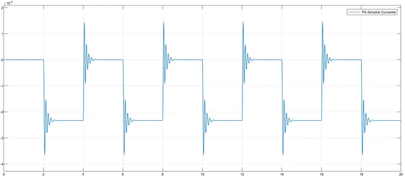
The plot showing the position of out with reference to the time. Here the delay time is 2 seconds, the switch is closed for 2 seconds then released. We run the system for 20 seconds so the graph is showing the output signals for 20 seconds.
The confiuration of the pulse generator is changed to meet the situation; the new input parameters are,
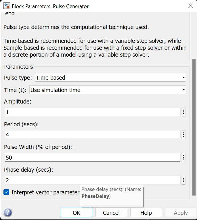
We delay the pulse generator with2 seconds with amplitude 1 and pulse time/period 4 seconds to make it in half with 50% width.
2. A simulink & simscape model by using a thermistor to sense the temperature of a heater & turn on or turn off the fan as per the condition
We have to create a simulink & simscape model by using a thermistor to sense the temperature of a heater and turn on or off thr fan as per the condition below;
Temperature source: 20 °C from 0 to 10 seconds, 27 °C from 10 to 30 seconds, 23 °C from 30 to 50 seconds
Fan conditions: ON if the temperature above 25 °C, OFF otherwise
Simulink & Simscape Blocks Used
- Signal Builder
- Simulink-PS & PS-Simulink Converter
- Scope
- Temperature Source
- Thermistor
- Resistor
- Voltage Sensor
- Battery
- Electrical & Mechanical Reference
- Solver Configuration
- Switch
- Constant Blocks
- Display
Simulink & Simscape Block Design
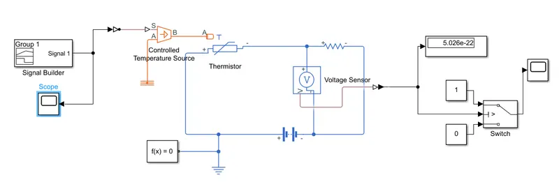
Here the signal builder block is used to give the input signal to the temperature source through a simulink-PS coverter as per the condition. A scope is conected to the signal builder to view the input signal
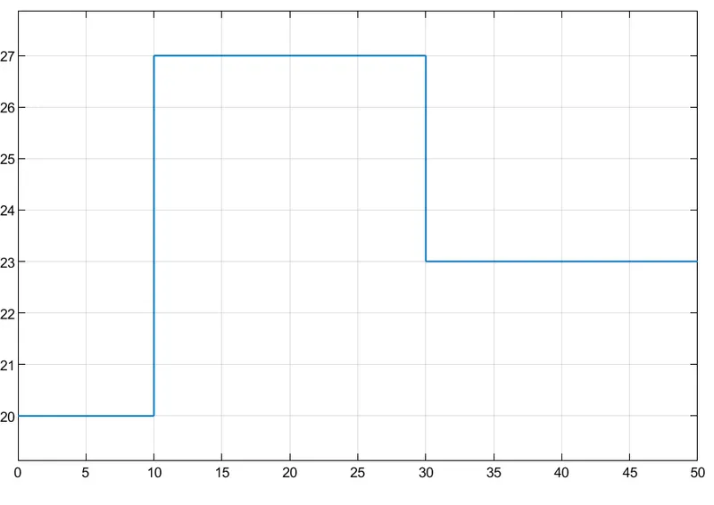
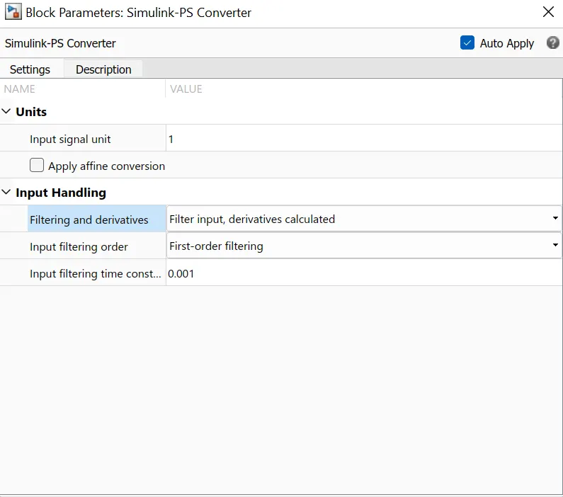
This is the plot when we look to the scope connected to signal builder after running the simulation for 50 seconds. For getting this plot we have to change the configuration of simulink-ps coverter block as showing below;
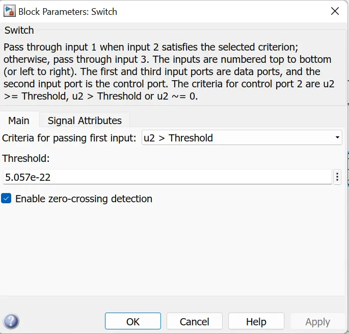
Then the other blocks are connected as per in the above design and run the simulation for 50 seconds. We need to ON and OFF the switch to meet our conditions, for that we have to configure the switch by giving the threshold value as same the final display value.
Here is the plot given by the scope connected to the swicth after running the simulation for 50 seconds;
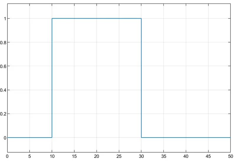
That means we have builded the model as per our conditions.