Project-1: Powertrain for aircraft in runways
PART A
1. Search and list out the total weight of various types of aircrafts.
The total weight W of the aircraft is simply the sum of the weight of all of the individual components. W = w(fuselage)+w(wing)+w(engines)+w(payload)+ w(fuel)+... To generalize, if we have a total of "n" discrete components, the weight of the aircraft is the sum of the individual i component weights with the index i going from 1 to n. The greek mathematical symbol sigma is used by mathematicians to denote this addition.
Total Weight Of Various Types Of Aircrafts
| AIRCRAFT | TOTAL WEIGHT |
| Average Sized Airplane [Eg: Boeing 737-800] | 80,000 kg |
| Fighter Jet [Eg: Boeing F18-Hornet] | 113,646 kg |
| Cargo Airplane [Eg: Airbus A300 600F] | 165,900 kg |
| Military Helicopter [Eg: Boeing RAH-66 Comanche] | 7,791 kg |
| Mid-Size Helicopter [Eg: Bell 212] | 5,080 kg |
| Turboprop Aircraft [Eg: Grand Caravan Ex] | 3,994 KG |
2. Is there any difference between ground speed and air speed?
Difference Between Ground Speed And Air Speed
The importance of the relative velocity explains why, even today, airplanes take off and land on different runways on different days. Airplanes always try to take off and land into the wind. This requires a lower ground speed, which means the plane can take off or land in the shortest distance travelled along the ground. Since runways have a fixed length, you want to get airborne as fast as possible on take-off and stopped as soon as possible on landing in the old days, a large " wind sock ' was hung near the runway for pilots to see which way the wind was blowing to adjust their take-off and landing directions. Now mechanical or electronic devices provide the information that is radioed to the cockpit. It is important to understand the relationships of wind speed to ground speed and airspeed.
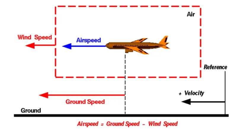
Wind Speed:
A reference point picked on the ground, the air moves relative to the reference point at wind speed. The wind speed is a vector quantity and has both magnitude and direction. The wind blowing against the motion of aircraft is called Head wind. We have defined a positive velocity to be in direction of the aircraft motion, head wind is a negative velocity. When the wind blows in the same direction of aircraft motion it is called Tall wind. The sign of wind is now positive.
Ground Speed:
The speed on which the aircraft moves relative to the point on the ground. Ground speed is a vector quantity.
Air Speed:
The relative velocity between the object and the air is called air speed. Airspeed cannot be directly measured from a ground position, but must be computed from the ground speed and the wind speed Airspeed is the vector difference between the ground speed and the wind speed.
| Air Speed | Ground Speed |
| Speed relative to air | Speed relative to ground |
| Measured quantity, using pitot tube | Calculated quantity, (Air Speed+Wind Velocity) |
Animation created by NASA for understanding the relative velocities: Animated Relative Velocities (nasa.gov)
3. Why is it not recommended to use aircraft engine power to move it on the ground at Airport?
There are number of reasons that to not use aircraft's engine to move it on the ground and they are:
1) Aircraft's engine creates a huge noise around which is not good for surrounding's around the airport.
2) Huge amount of fuel is consumed by the engine which is again a disadvantage, so by taxing fuel can be saved for the aircraft's flight.
3) If engine power is used by the aircraft for its travel to runway it will cause wear and tear to the engine and we don't want that before a flight cause it will create unnecessary problems to both the passangers and airport staff.
4) It will cause various injuries and damage to the near by population and property if a pilot losses control of the airplane traveling on the ground using engine power.
4. How an aircraft is pushed to runway when its ready to take off?
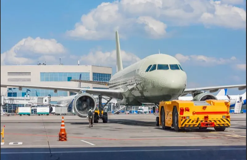
Pushback is when an aircraft is pushed backwards away from the airport gate by vehicles called tugs or tractors .Closer to departure , an aircraft tug will park right in front of the nose whool .The tug might be directly attached to the plane's nose gear with a tow bar , or could be a " wheel - lift " tug .These tugs cradle the nose gear , then lift it up before moving the plane .That gives the tug driver control over the plane's direction during pushback .New taxi technologies are appearing , like pilot - controlled tugs , and electric motors mounted to the plane's landing gear .Both promise to save fuel , and reduce airport noise.
5. Learn about take off power, tyre design, rolling resistance, tyre pressure, brake forces when landing.
Take Off Power
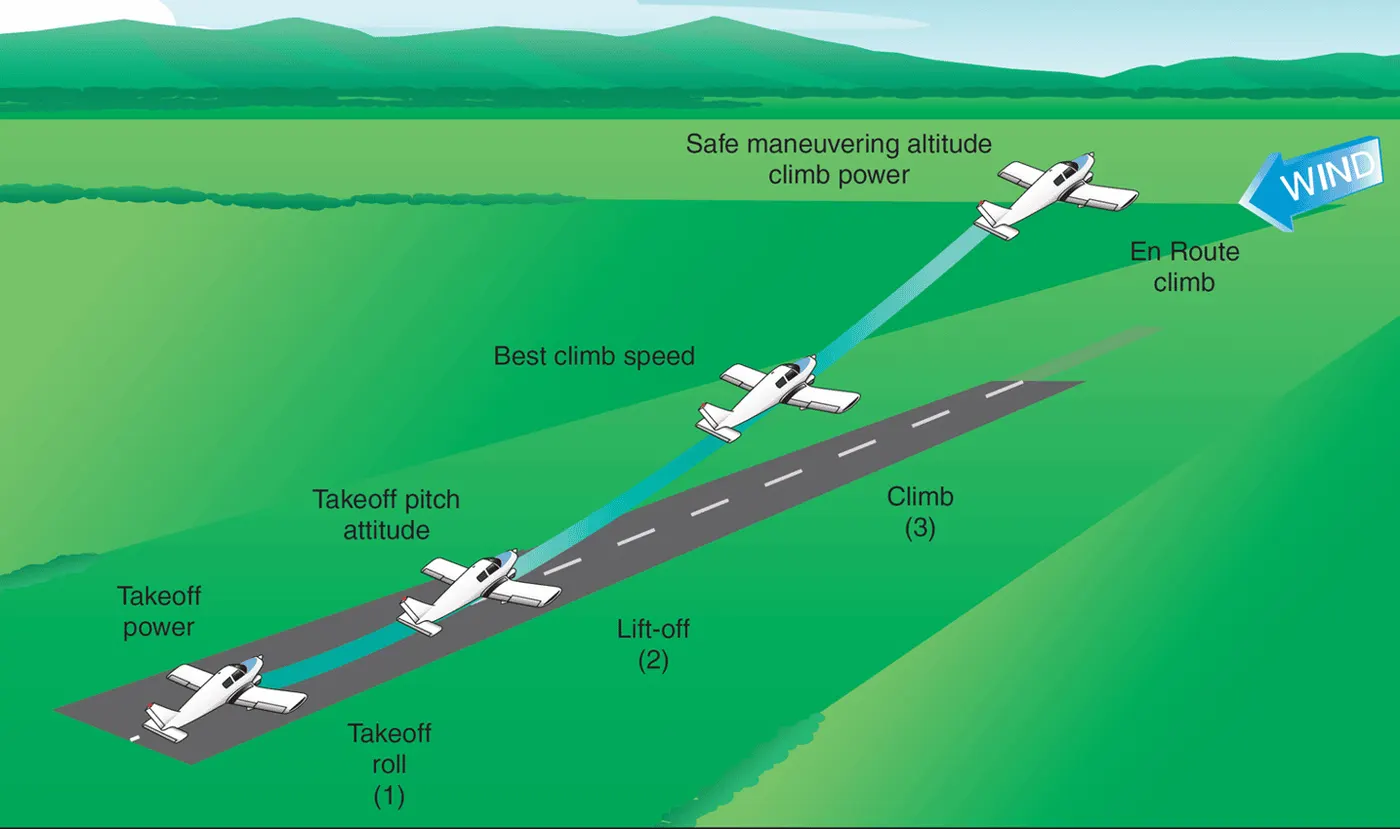
Take-off is the phase of flight in which an aerospace vehicle leaves the ground and becomes airborne. For aircraft traveling vertically , this is known as Lift-off. For aircraft that take off horizontally , this usually involves starting with a transition from moving along the ground on a runway. For light aircraft , usually full power is used during takeoff. Large transport category (airliner) aircraft may use a reduced power for takeoff , where less than full power is applied in order to prolong engine life , reduce maintenance costs and reduce noise emissions.
After taxiing onto the runway , the airplane should be carefully aligned with the intended takeoff direction , and the nose wheel positioned straight , or centered. After releasing the brakes , the throttle should be advanced smoothly and continuously to takeoff power. An abrupt application of power may cause the airplane to yaw sharply to the left because of the torque effects of the engine and propeller. This will be most apparent in high horsepower engines. As the airplane starts to roll forward , the pilot should assure both feet are on the rudder pedals so that the toes or balls of the feet are on the rudder portions , not on the brake portions.
Take-off performance can be predicted by using a simple measure of Acceleration of the aircraft anong the runway based on force equilibrium.
The force involved will be
T- Thrust of propulsion system pushing aircraft along runway
D - Areodynamic Drag of vehicle resisting the aircraft motion
F - Rolling resistance friction due to the contact of wheels of skids on the ground
During take-off run the imbalance in these forces will produce an acceleration along the runway,
dv/dt = (T-D-F)/m
Where dv/dt is the acceleration along the runway and m is the mass of the vehicle.
Tyre Design
Designing aircraft tires is a very intense undertaking. The tyre is designed to withstand heavy loads while landing , take off , taxing , and parking. The number of wheels required for aircraft increases with the weight of the aircraft , as the weight of the aeroplane needs to be distributed more evenly. Aircraft tyre generates more heat during landing. Aircraft drags the wheel until they match the rotational velocity of wheels. Due to this heat generates. However , each tyre is built to operate within a given temperature. This is known as vulcanization temperature. During the course of its use , if the tire is heated past the vulcanization temperature , it begins to wear gradually.
Two types of tyres are used in aircraft applications :
Bias-Ply tyres & Radial Tyres
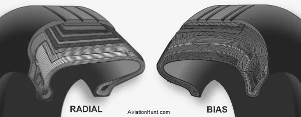
Radial Tyre :
It has fibre strands of the ply fabric oriented at 90° to the direction of rotation and the tyre sidewall. This restricts flexibility bidirectional and the flexibility of the sidewall while it strengthens the tyre to carry heavy loads. Due to their unique construction most radial tyres are resistant to penetration ad cuts. Due to stiffer tread they distribute weight evenly. Thus provide greater traction. Radial tyres have an advantage in term of reducing the heat better.
Bias-ply Tyre :
It has the fabric bias oriented with and across the direction of rotation and the sidewall. Since fabric can stretch on the bias , the tyre is flexible and can absorb loads. Tyre strength is obtained by adding plies. It is cut resistant is sidewall area. These tyres do not offer as much smoothness in terms of riding quality.
Rolling Resistance
The friction between aircraft and runway will be proportional to the normal force exerted by aircraft on the runway.
F = μ(W-L)
The normal force will be the difference between the weight (W) of the aircraft and load (L), the frictional coefficient (μ) will be typically of a magnitude of 0.02 for a standard tarmac runway.
Tyre Pressure
Aircraft tyres operate at such high extremes of pressure , load , and speed , their care and service is critically important. The most important action an operator can take to prevent tyre - related events is to maintain proper tire inflation pressure. Failure to keep aircraft tires properly inflated can lead to very serious consequences. One relatively easy way to help avoid those consequences is to check tire pressures regularly and service them as necessary.
Following these three actions is a good way to make sure you get the most value out of your tires and contribute to the safe operation of your aircraft :
1. Perform daily pressure checks with a calibrated gauge
2. Target the highest pressure recommended in the AMM or POH (105 percent of operating pressure)
3. Compensate for ambient temperature changes
Brake Forces When Landing
Stopping a 200-tonne aircraft landing at 180 mph requires a lot of braking force. To do this either hydraulic brakes or electric brakes are used. Hydraulic brakes put on weight of the aircraft. Now a days designers use electric brake system. The aim of brake force when landing is to minimise the distance.
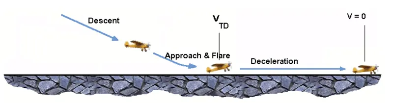
The touch down velocity should be approximately the stall speed of the aircraft in landing configuration. This will be achieved by increasing the drag and decelerate the aircraft to minimum flying speed. The deceleration on the landing roll from to will be accomplished by braking and reverse thrust. This can be solved by the average acceleration approach that was used to estimate the take-off roll.
dv/dt = (-T-D-F)/m
where,
T - Thrust of propulsion system pushing aircraft along runway
D - Aerodynamic Drag of vehicle resisting the aircraft motion
F - Rolling resistance friction due to the contact of wheels or skids on the ground
m - Mass
So ;
Brake Force = Mass*Deceleration
PART B
6. A. With necessary assumptions, calculate the force and power required to push / pull an aircraft by a towing vehicle.
B. Develop the model for the calculated force and power using Simulink.
A.
The force to move an aircraft on an ubsolute flat runway with no wind at constant speed is equal to the rolling resistance between the aircraft and tarmac.
The rolling resistance can be calculated as:
Fr = C. mr. g
where,
Fr - Rolling Resistance
C - Rolling Resistance Coefficient
mr - Rolling Mass
g - Acceleration Due To Gravity
If the mass of the aircraft is 40000 kg and rolling resistance between the aircraft and tarmac is 0.02;
Fr = 0.02 * 40000 * 9.81
= 7848 N
This force can be delivered by a pulling truck. Enough weight of truck is required to create friction forces against the tarmac that equal to the aircraft rolling resistance.
The friction force for the puller can be calculated by;
Ff = μW
= μ*mf*g
where,
Ff - Frictional Force
μ - Frictional Coefficient
W - Weight
mf - Frictional Mass
The required mass for pulling truck:
The frictional coefficient between a pulling truck rubber wheels and dry tarmac is 0.9
Since the pulling trucks are connected to the aircraft nose wheels clos to tarmac we simplify the calculation of required truck mass to:
mf = 7848/(0.9*9.81)
= 889 kg
Power required for pulling truck with a velocity of 5 m/s:
P = F* V
where,
F - Total force acting on the truck
V - Velocity of truck
P = 7848*5
= 39.24kW
B.
Simulink Model For Calculating Force And Power
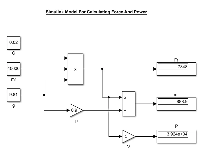
Blocks Used:
- Constant Block
- Product Block
- Gain Block
- Division Block
Simulink File: Force & Power Of Aircraft
7.
A. Design an electric powertrain with type of motor, it’s power rating, and energy requirement to fulfill aircraft towing application in Simulink. Estimate the duty cycle range to control the aircraft speed from zero to highest. Make all required assumptions. Prepare a table of assumed parameters. Draw a block diagram of powertrain.
(Hint :DC7 Block)
B. Also, Design the parameters in excel sheet.
A.
Here I considered Aircraft with mass of 50000kg and towing vehicle ( TWIN 6500 ) of 1180kg for pull / tow of aircraft
Here by we utilised DC7 chopper block in order to produce the required torque for towing puprose.
The battery parameters given for the chopper to drive is taken from;
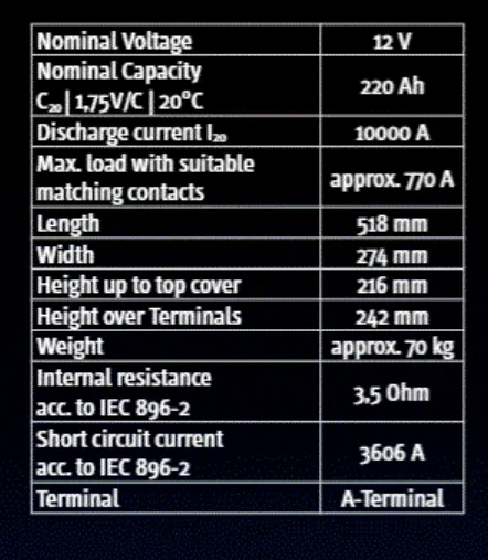
Here the towing vehicle 4 batteries are arranged in series combination as we are using for high torque application.
So the overall voltage & current will be V = 48v and I = 880Ah respectively.
Now the RPM of the motor is defined by considering its wheel radius and the max towing speed of the vehicle i.e,
N = 6kmph = 1.667m/s
Rpm of vehicle = N / r ; where N = speed of vehicle , r = radius of vehicle
Rpm = 1.667 / 0.127m = 125.29 => w = 125.29rpm.
Radius of the tyre = height of towing vehicle - ground clearance = 344-88.5 = 258.5 mm (diameter)
= 0.129m (radius)
Now to calculate the armature resistance of motor we opt
=> battery 'V' / battery resistance'r' = 48v / 4 * ( 3.5ohm ) = 3.428A
Armature resistance = V / I = 48v / 3.428
= 14.4ohm
Required torque ( T ) = F.r / G.η ;
F = force at wheels , r = radius of wheel , G = gear ratio = 10 , η = efficiency
T = ( 9.7591kN ) * ( 0.127m ) / ( 10 * 0.87 )
= 142.4Nm
Here we consider the motor power of 18kW to meet our load torque for towing operation.
Now the duty cycle by above data is ' Duty Cycle ' = Po / Pi ; Po output power , Pi = input power
Duty Cycle ( D ) = 16.26kW / 18kW = 0.9033 = 90.33 %
Simulink Model
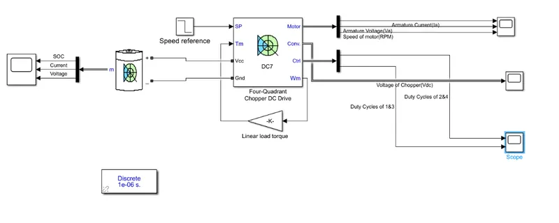
We used Li - ion battery connected to DC7 chopper with necessary parameter changes for towing , and we observed the output waveforms of la , V , Vdc , duty cycle of IGBT's , speed of motor.
Result:
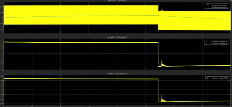
Here we can notice the armature current it is drawing at 480A which represents the high torque application and with a low speed nearly 150rpm.
Now to accomplish this towing we assumed some parameters. They are :
Efficiency ( η ) = 87%
Gear ratio ( G ) = 10
co- efficient of friction = 0.75
Mass of aircraft = 50ton ( 50000kg )
rolling resistance coefficient ( c ) = 0.01
Air density ( p ) = 1.225kg / m^3
Drag coefficient ( Cd ) = 0.025
Frontal area of aircraft ( A ) - 100.5211m^2
Towing time = 18sec
Velocity of Towing vehicle = Velocity of aircraft
By considering all these parameters and the name plate parameters of MOTOTOK TWIN 6500 we are able to tow the vehicle.
Here we are unable to connect this chopper to a real - time load of aircraft body because of simscape and simuink conversion in the blocks we use for towing and aircraft respectively.
B.
Parameters in excel sheet
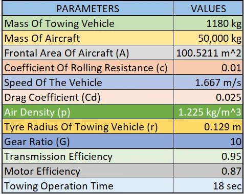
Excel File: Aircraft & Towing Vehicle Parameters