Project
Aim:
To prepare a technical report of simulation of BAJA All-Terrain Vehicle (ATV) under different conditions.
Objective:
Carry out a system-level simulation of BAJA All-Terrain Vehicle (ATV) and prepare the technical report avout the model properties under different conditions.
All Terrain Vehicle (ATV):
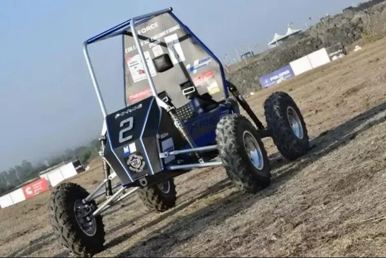
An all-terrain vehicle ( ATV ), also known as a quad, three-wheeler, four-track, four-wheeler, or quadricycle, as defined by the American National Standards Institute (ANSI) is a vehicle that travels on low-pressure tires, with a seat that is straddled by the operator, along with handlebars for steering control.
CONTINUOUSLY VARIABLE TRANSMISSION (CVT)
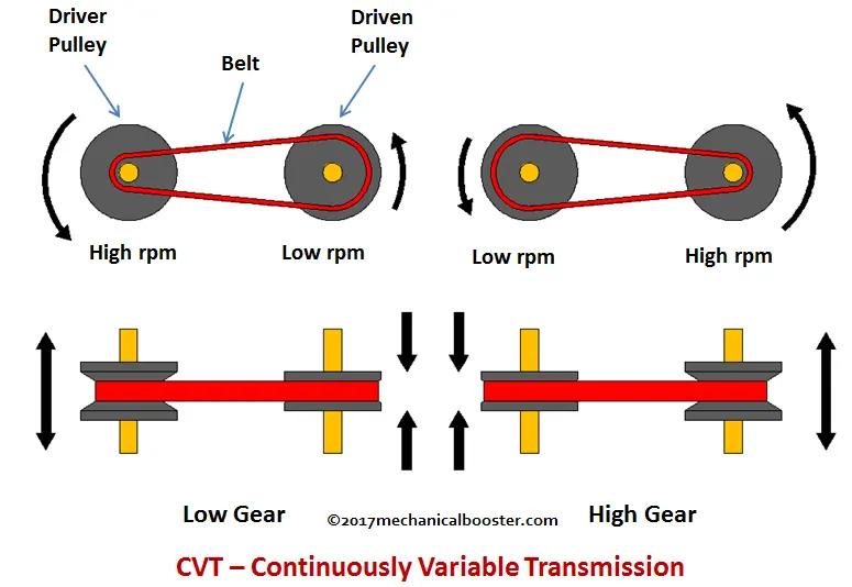
A CVT, or continuously variable transmission, seamlessly changes through an unending range of effective gear ratios while drivIng, whereas other kinds of mechanical transmissions offer a fixed number of gear ratios and have hard shifts between each. CVT transmission systems are also known as single-speed, shiftless, and stepless transmissions. While a traditional transmission uses a wide variety of intricate parts to shift between a range of preset gears, most CVT systems work through a pulley system. In short, this system consists of cones at each pulley connected via a chain belt. The cones can move to increase or decrease the belt diameter to change gear ratios, allow for quick shifting into the needed ratio for increased power, and boost fuel economy. One pulley in the CVT is connected to the engine and the other directs power to the wheels. The width of these pulleys changes based on the needed power; as one gets larger, the other gets smaller. This allows a CVT to deliver strong and seamless acceleration.
STUDY#1
CASE 1:
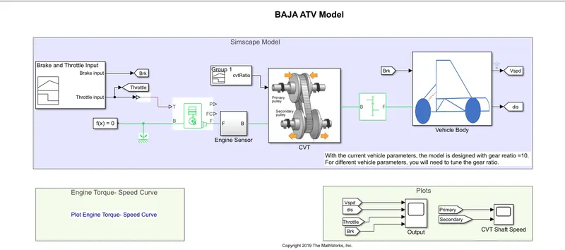
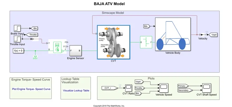
SIMULINK MODEL OF BAJA ATV WITH CVT
Signal Builder
The input signal is created by using signal builder block. There are 2 input signals used here one is Brake input and the other is Throttle input signal. Here is the plot of the input signals;
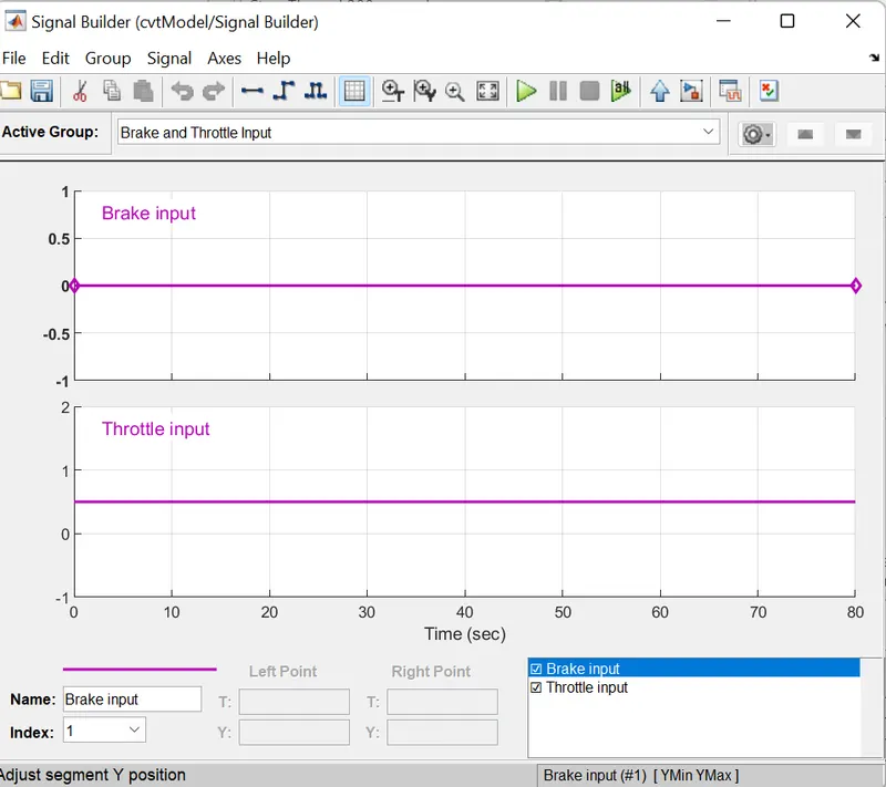
The Brake input is 0 and Throttle input is 0.5, it is set as constant.
Generic Engine
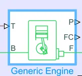
Represents a system-level model of spark-ignition and diesel engines suitable for use at initial stages of modeling when only the basic parameters are available. Optional idle speed and red line controllers are included.The throttle input signal T lies between zero and one and specifies the torque demanded from the engine as a fraction of the maximum possible torque. If the engine speed falls below the Stall speed, the engine torque is blended to zero. If the engine speed exceeds the Maximum speed, the simulation stops and issues an error message.Connections F and B are mechanical rotational conserving ports associated with the engine crankshaft and engine block, respectively. Connections P and FC are physical signal output ports through which engine power and fuel consumption rate are reported.
Engine Sensor
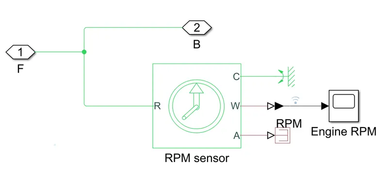
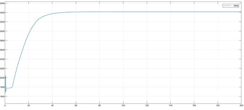
It will find the rpm of the engine. Here is the plot of engine rpm;
CVT Block
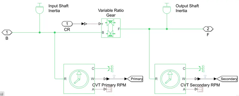
This is the simscape model for cvt block. The Variable Ratio Gear block represents a variable ratio gearbox such as implemented by mechanical belt CVT, electric, or hydraulic transmissions. The physical signal input r defines the ratio of input to output angular shaft velocities. Connections B (base) and F (follower) are mechanical rotational conserving ports. Specify the relation between base and follower rotation directions with the Output shaft rotates parameter. The input signal for gear ratio is provided by using a signal builder.
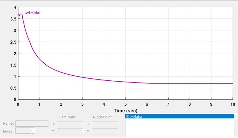
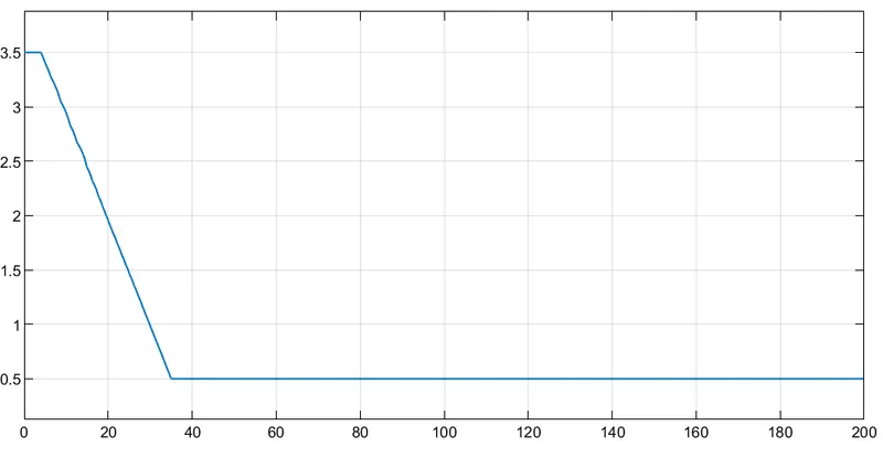
plot for input gear ratio (cvt ratio)
Engine Tourque - Speed Curve
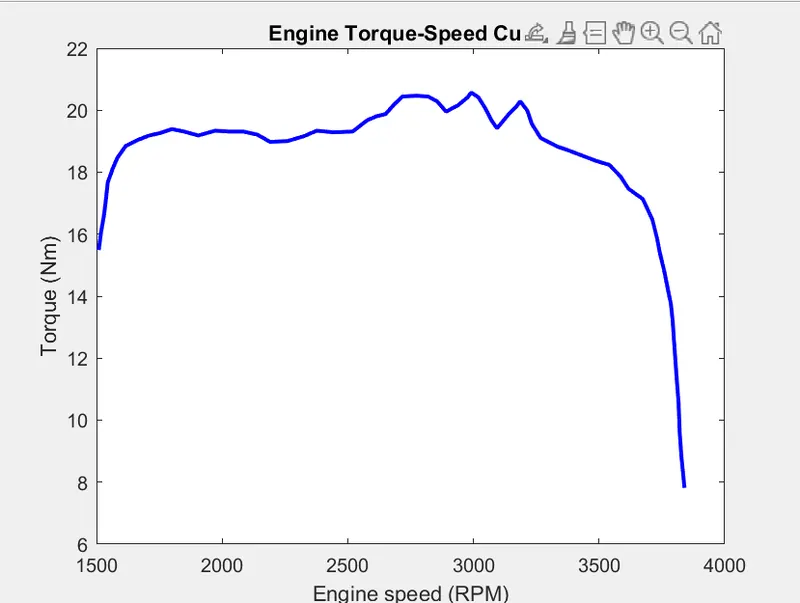
This is the graph showing torque vs engine speed input.
Vehicle Body
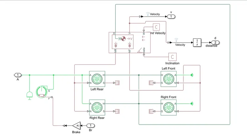
The all parameters for the vehicle body design is assigned in this such as; mass, number of wheel per axle etc.
OUTPUT OF THE MODEL
- VELOCITY OF VEHICLE
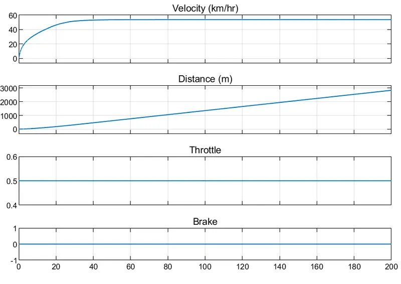
For a half throttle the vehicle attain a velocity around 57 km/hr. There is no effect of brakes beacuase its value is 0 so there is no change in the velocity.
- CVT SHAFT RPM
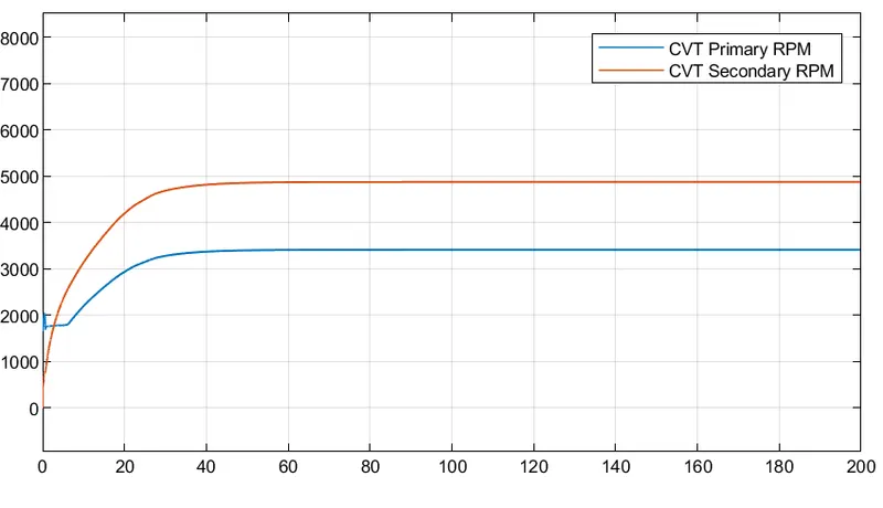
These plot represents the variation in the rpm/angular velocity of input and output shaft of the CVT system.
CASE 2:
SIMULINK MODEL OF BAJA ATV WITH CVT USING DASHBOARD
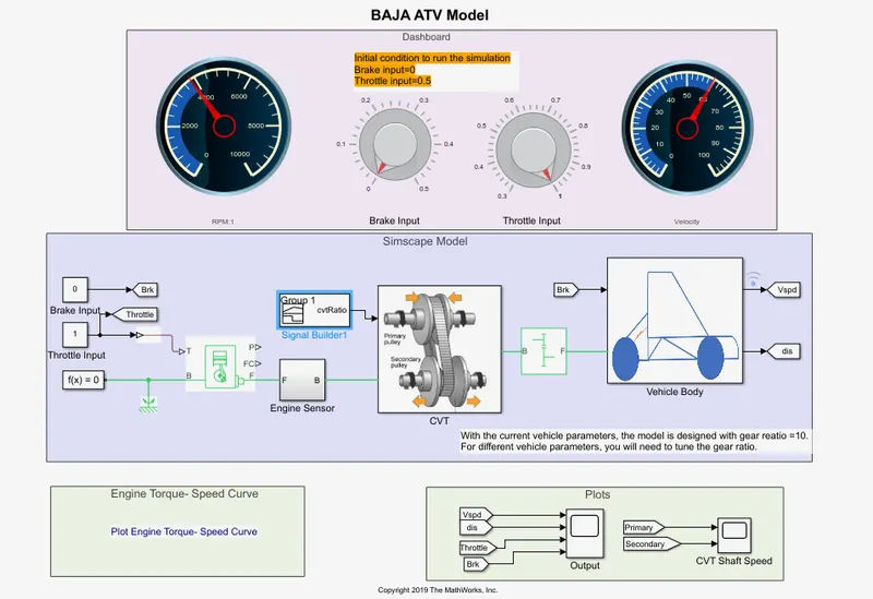
In this case the signal builder is replaced by a dashboard which contains knob to control the input. We can control both the iput throttle and brake in real-time by using the knob. All the other operations and parameters are same as in the previous case.
OUTPUT OF THE MODEL
- VELOCITY OF VEHICLE
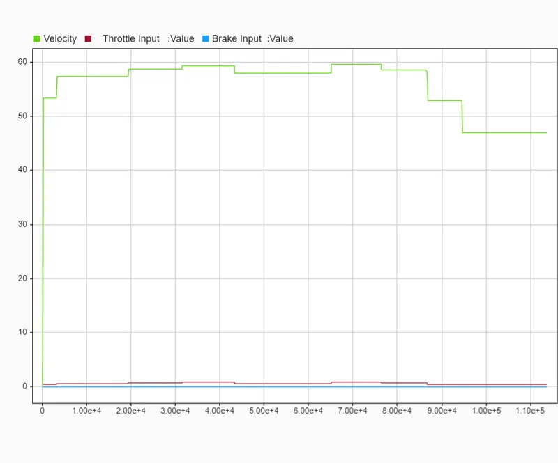
This is the graphical representation for the change in velocity when I changed the Throttle input continuousely. There is no brake engaging here. So input throttle only has the effect in velocity.
- CVT SHAFT RPM
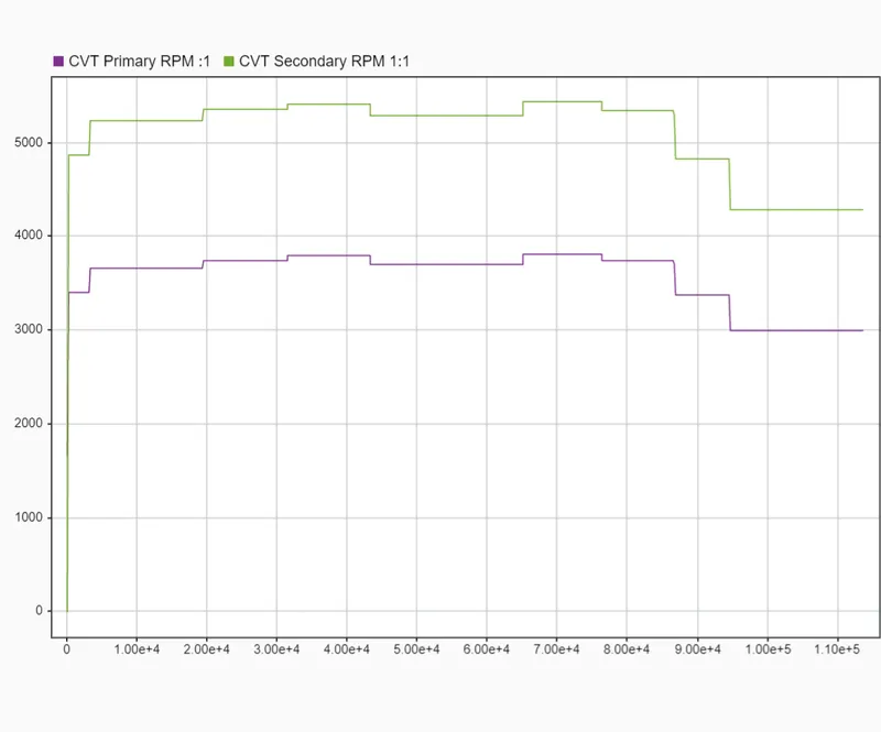
This is the graphical representation of CVT primary and secondary rpm to the change in throttle over the time.
STUDY#2
CASE 1:
SIMULINK MODEL OF BAJA ATV WITH CVT USING LOOKUUP TABLE
CVT Block
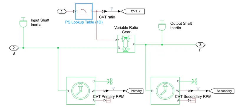
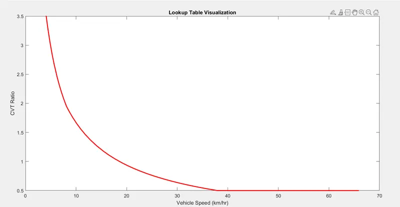
Instead giving the gear ratio input to CVT through a signal builder block here using a lookup table. This is the only difference between this model and first model.
Lookup Table Visualization CVT Gear Ratio
OUTPUT OF THE MODEL
- VELOCITY OF VEHICLE
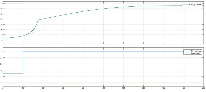
- CVT SHAFT RPM
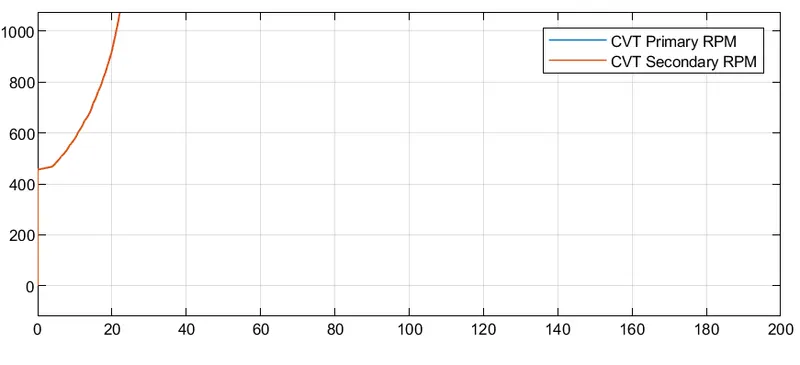
CASE 2:
SIMULINK MODEL OF BAJA ATV WITH CVT USING DASHBOARD & LOOKUP TABLE
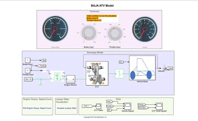
In this model the dashboard is using to controll the input 'THROTTLE & SPEED'. Here also using the lookup table.
OUTPUT OF THE MODEL
- VELOCITY OF VEHICLE
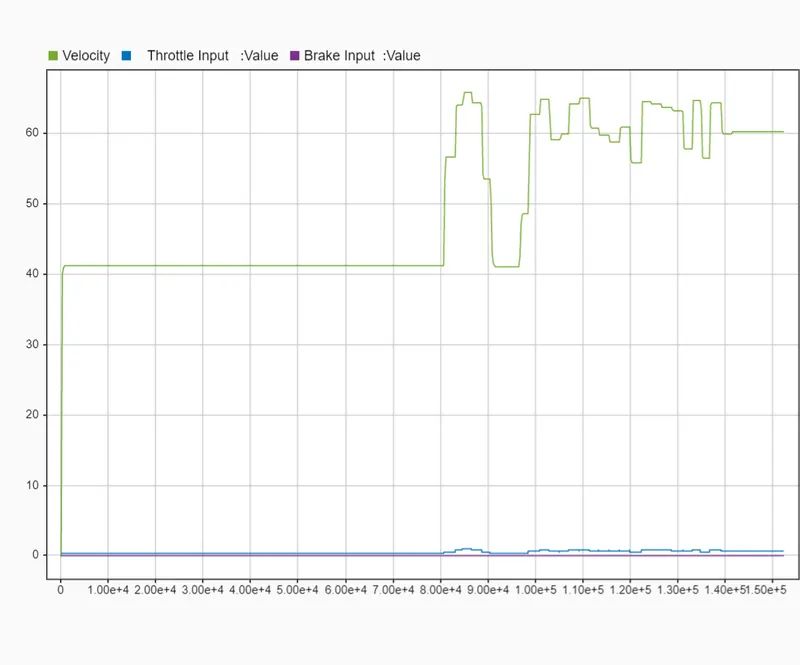
This is the plot showing the curresponding velocity change when I use the dashboard to varie the throttle. And brake remains 0.
- CVT SHAFT RPM
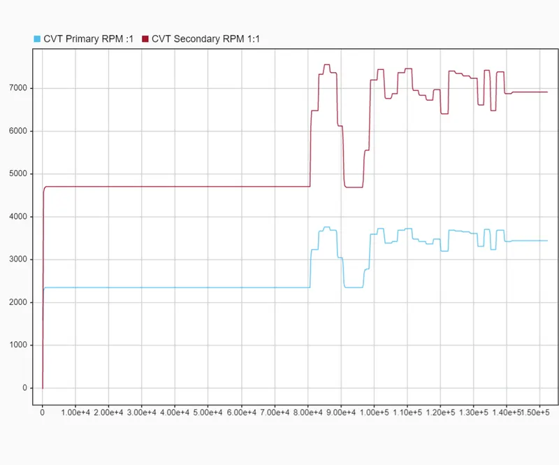
This is the curresponding change is the CVT primary & secondary rpm to the input throttle change.
Conclusion:
We have successfully analysed 4 different models of BAJA ATV WITH CVT and recorded the output with respect to the variation in input over time.
Ref File: BAJA ATV WITH CVT