Week - 4
1.
Objective: Implement the control logic chart for Washing Machine using Stateflow process:
- Start simulink and create blank model.
- Search for chart block in stateflow category of library browser.
- Open the chart block and select the junction feature from the stateflow window.
- Control logic for washing machine is such that it should soak the water for the first 200sec followed by washing time of 100sec. Rinsing the water for the next 20sec followed by drying time of 50sec.
- After finishing the control logic run the STATEFLOW and check the sequence of operation for 370sec.
Blocks used
- Chart
- Display
- Constant
- Lamp
- Rockstar switch
Logic explanation:
A rockstar switch is used with a constant block to supply the power and as water.
A lamp is used to indicate the power status & water status. The power status is checked at the entry for every state
and water supply is checked for the soaking and rinsing process. The timing for each state is as per the given inputs.
The status of the running process can be seen by the glowing lamp corresponding to the process name.
Washing machine logic:
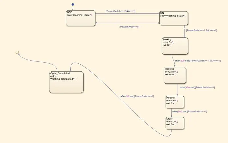
In the above control logic first state is created with 2 conditions for power supply.
One is with power supply available(PowerSwitch==1) and second with water supply available(W==1).
If the power supply at entry is 1 and water supply is on, then machine will get activated and start the next process of operation.
Next 4 operation states are Soaking, Washing, Rinsing and Drying with their time of operation as 200sec for soak,
100sec for wash, 20sec for rinsing and 50sec for drying. Entry and exit condition of the state are
kept as O i.e at entry of operation state it is O and as operation completes it is indicated by 1 for every state.
Symbols pane:
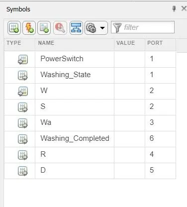
Here,
PowerSwitch & W(water supply) is as input given while all other like Washing_state,D(dryer), Wa(washing), S(soaking), R(rinsing), Washing_completed are all output given.
COMPLETE SIMULINK MODEL:
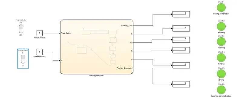
Here all LED glown as Green means all process has been completed and all display output as 1.
2) OBJECTIVE: IMPLEMENTATION OF CONTROL LOGIC FOR GEAR SHIFT USING STATEFLOW
BLocks used:
- chart
- display
- constant
- lamp
- rockstar switch
- slider
Process:
The speed ranges from 0 to 100 and the slider is used to send the input.
The 1st gear has speed values from o to 15 so the entry condition for the 1st gear is 0<=speed and speed<=15
and exit condition is when speed greater than 15.
Similarly for 2nd gear, the entry condition is 16<=speed and speed<=25'
In the same way for each gear, the entry and exit condition are specified and the out is mapped to the lamp and display block.
Logic:
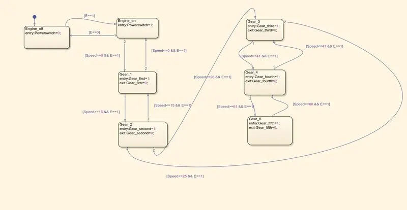
Symbols pane:
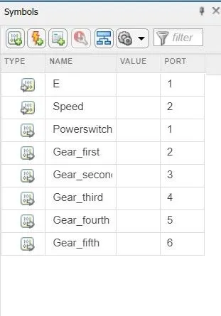
Here E and Speed are input blocks and remaing are output blocks.
Simulink model:
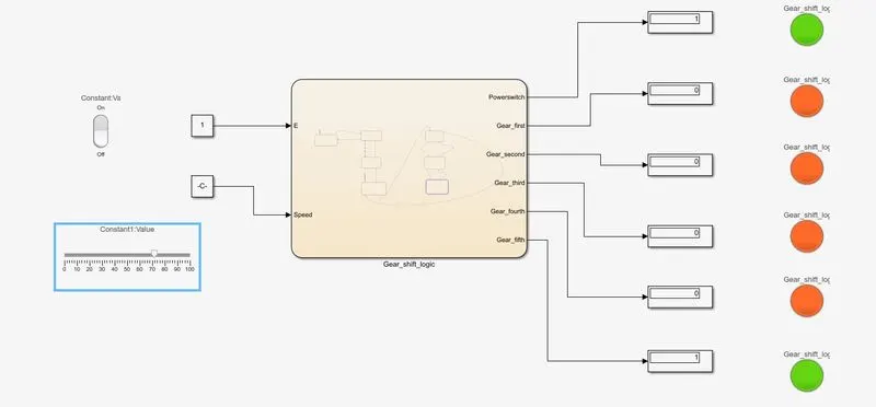
At speed 70Kmph which is above 61Kmph Gear 5 is implemented and Gear_fifth LED is green and display output as 1.