Week-7 Challenge: DC Motor Control
1. A. Explain a MATLAB demo model named ‘Speed control of a DC motor using BJT H-bridge'.
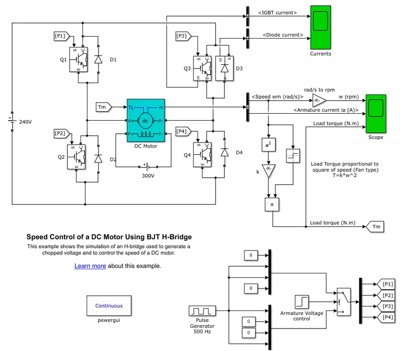
MODEL BLOCK DIAGRAM
Fundamental blocks:
- DC voltage source
- IGBT block
- DC Motor block
- Pulse generator block
- Gain block
- Mux
- DeMux
- GoTo block
- From block
- Bus Selector
- Scope
Model Description:
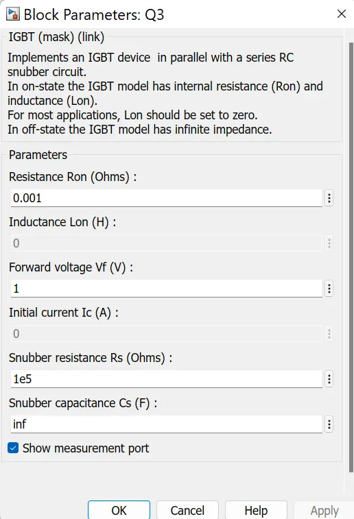
- The Bipolar Junction Transistor (BJT) when used for power switching applications, operates as an IGBT.
When it is conducting (BJT operating in the saturated region), a forward voltage Vf is developed between collector and
emitter (in the range of 1 V). Therefore, the IGBT block can be used to model the BJT device.
The IGBT block does not simulate the gate current controlling the BJT or IGBT. The switch is controlled by a Simulink signal (1/0).
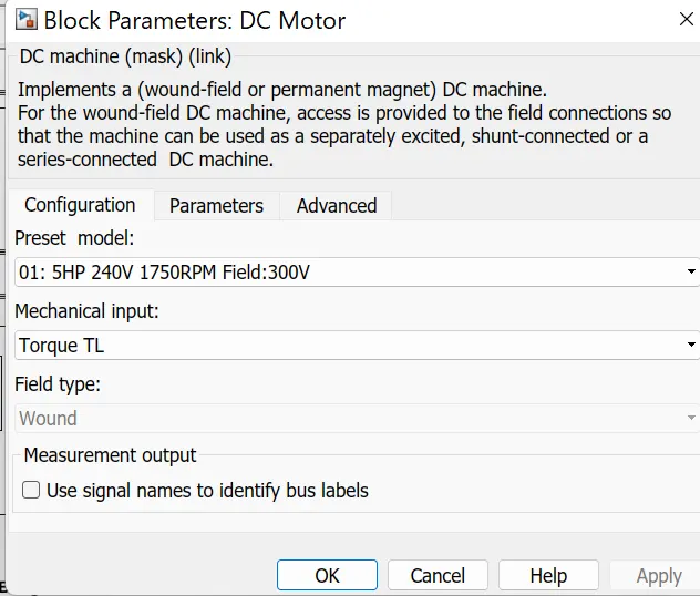
The DC motor uses the preset model (5 HP 24V 1750 rpm). It simulates a fan type load (where Load torque is proportional to square of speed).
The armature mean voltage can be varied from 0 to 240 V when the duty cycle (specified in the Pulse Generator block) is varied from 0 to 100%.
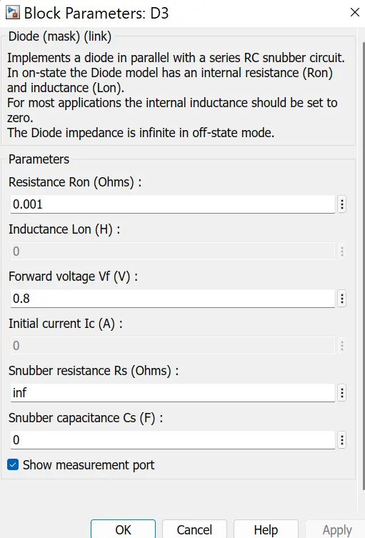
The H-bridge consists of four BJT/Diode pairs (BJT simulated by IGBT models). Two transistors are switched simultaneously:
Q1 and Q4 or Q2 and Q3. When Q1 and Q4 are fired, a positive voltage is applied to the motor and diodes D2-D3 operate as free-wheeling
diodes when Q1 and Q4 are switched off. When Q2 and Q3 are fired, a negative voltage is applied to the motor and diodes D1-D4 operate as
free-wheeling diodes when Q2 and Q3 are switched off.
IGBT BLOCK:
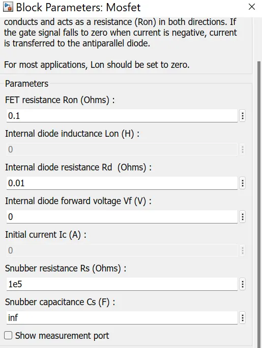
DIODE BLOCK PARAMETERS:
DC MOTOR BLOCK:
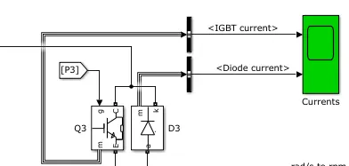
IGBT AND DIODE connected to scope:
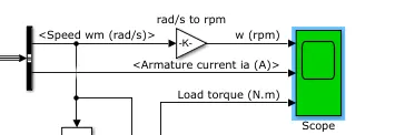
SCOPE DATA:
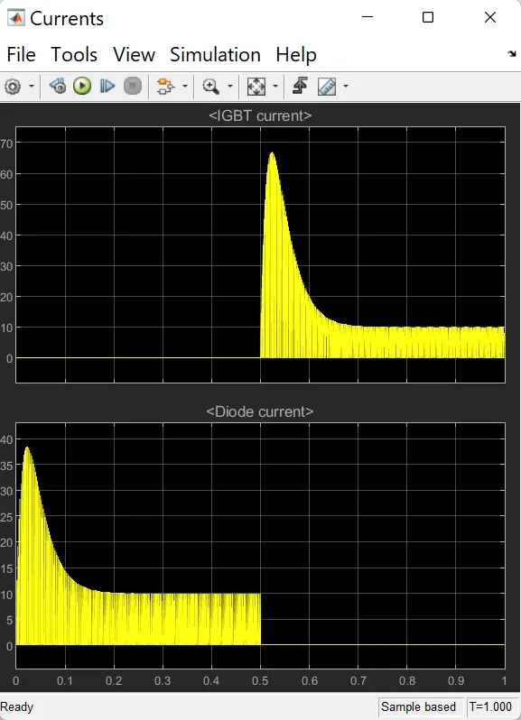
Result:
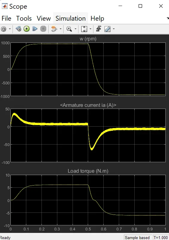
RESULT:
1 B:-) B. Comment on the armature current shoot-up from the scope results.
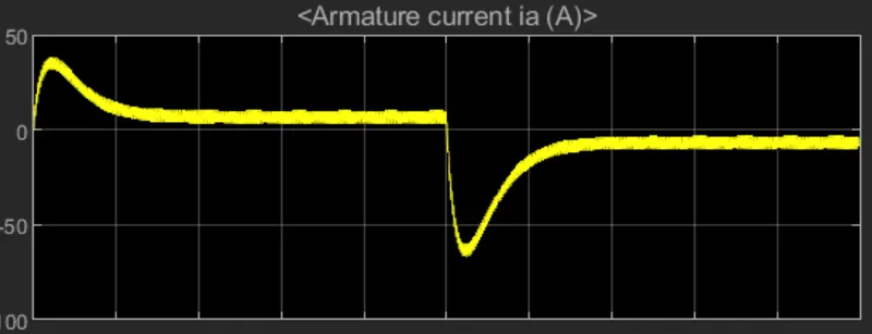
- As you know you can predict that at the time of starting you can predict that at the time of starting the generator
action of the motor is not present as it is not rotating just at the time of starting so because of that there is no back EMF
so if you substitute back EMF = 0 in the voltage equation of the motor you can get the current as the applied voltage divided by the armature resistance
so the applied voltage being typicaly around some 100s of volts and armature resistance being something like less than 1 ohm
so because of that with numerator being large denominator being small you get a large value of current.
- By changing the PWM we can improve the armature current waveform.
1.C. Refer to the help section of ‘The Four-Quadrant Chopper DC Drive (DC7) block’. Compare it with the H-bridge model.
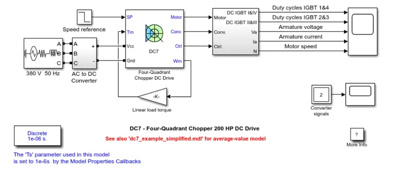
Comparison of Four-Quadrant chopper DC-7 block vs H-bridge model
| S No | H-Bridge model | Four quadrant chopper DC-7 block model |
| 1 | Powergui of continuous type used | Powergui of discrete type used |
| 2 | Operates in two modes only | Operates in four modes |
| 3 | No PI-Regulator | PI regulator is present |
| 4 | Efficiency is less | Efficiency is more |
| 5 | Used in robotics for forward and reverse motoring of motor | used in swiching of power control and signal applications |
------------------------------------------------------------------------------------------------------------------------------------------------------------------------------------
2. Develop a 2-quadrant chopper using simulink & explain the working of the same with the relevant results.
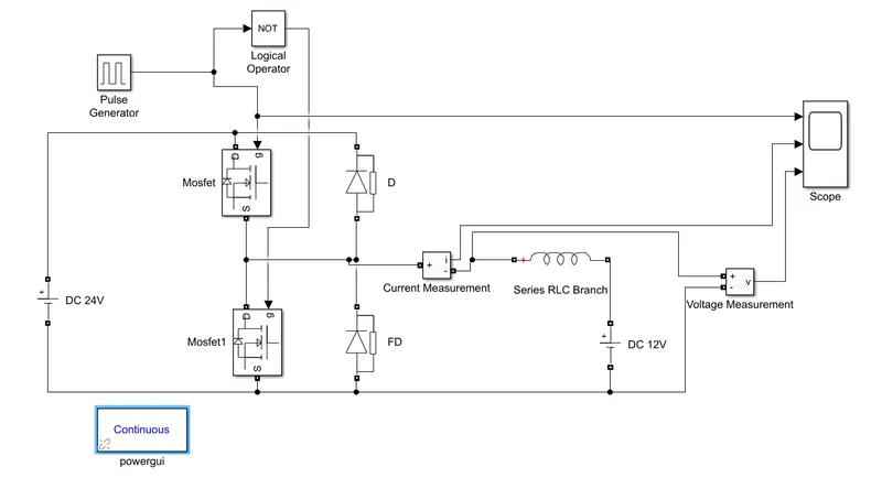
2-quadrant chopper simulink model
Working of 2-quadrant chopper:
- Type C chopper is obtained by connecting type –A and type –B choppers in parallel. We will always get a positive output voltage V0
as the freewheeling diode FD is present across the load. When the chopper is on the freewheeling diode starts conducting and the output
voltage v0 will be equal to Vs. The direction of the load current i0 will be reversed. The current i0 will be flowing towards the source
and it will be positive regardless the chopper is on or the FD conducts. The load current will be negative if the chopper is or the diode D
conducts. We can say the chopper and FD operate together as type-A chopper in first quadrant. In the second quadrant, the chopper and D
will operate together as type –B chopper.
The average voltage will be always positive but the average load current might be positive or negative. The power flow may be life the
first quadrant operation ie from source to load or from load to source like the second quadrant operation. The two choppers should not
be turned on simultaneously as the combined action my cause a short circuit in supply lines. For regenerative braking and motoring these
type of chopper configuration is used.
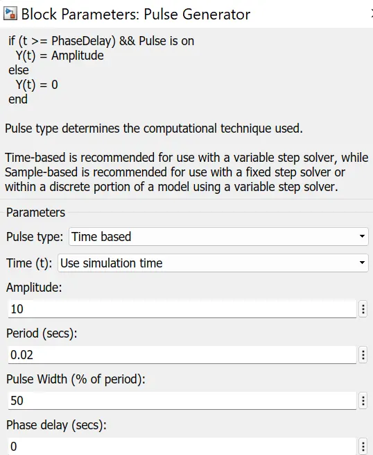
Result:
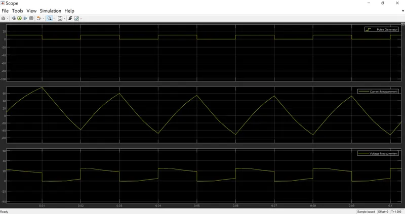
Result:
- Pulse generator is shown in the above graph with 50% duty cycle.
- Current waveform with respect to time is shown in the graph.
- Current waveform is continuous because of freewheeling diode.
- Chopped Voltage waveform is shown in the result.
------------------------------------------------------------------------------------------------------------------------------------------------------------------------------
3. Explain in a brief about operation of BLDC motor.
BRUSHLESS DC MOTOR:
- The BLDC motor is widely used in applications including appliances, automotive, aerospace, consumer,
medical, automated industrial equipment and instrumentation.
The BLDC motor is electrically commutated by power switches instead of brushes. Compared with a
brushed DC motor or an induction motor, the BLDC motor has many advantages:
1.Higher efficiency and reliability
2.Lower acoustic noise Smaller and lighter
3.Greater dynamic response
4.Better speed versus torque characteristics
5.Higher speed range
6.Longer life
CIRCUIT DIAGRAM OF SINGLE PHASE AND THREE PHASE BLDC MOTOR:
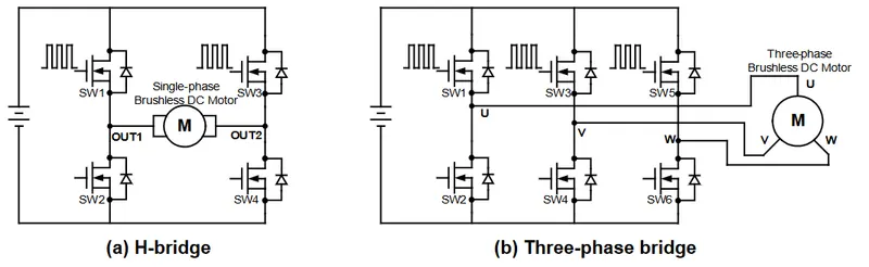
Single-Phase BLDC Motor:
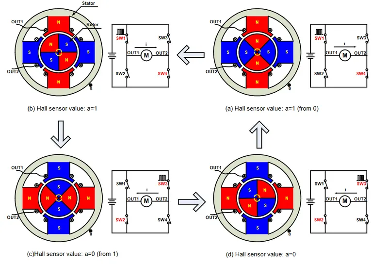
FIGURE 1: Single-Phase BLDC Motor
- BLDC commutation relies on feedback on the rotor position to decide when to energize the corresponding switches to generate
the biggest torque. The easiest way to accurately detect position is to use a position sensor. The most popular position sensor device
is Hall sensor. Most BLDC motors have Hall sensors embedded into the stator on the non-driving end of the motor. Figure 1 shows the
commutation sequence of a single-phase BLDC motor driver circuit. The permanent magnets form the rotor and are located inside the stator.
A Hall position sensor (“a”) is mounted to the outside stator, which induces an output voltage proportional to the magnetic intensity
(assume the sensor goes HIGH when the rotor’s North Pole passes by, and goes LOW when the rotor’s South Pole passes by).
SW1 and SW4 turn on when Hall sensor output is HIGH, as shown in Figure 1(a) and (b). At this stage, armature current flows through
the stator windings from OUT1 to OUT2 and induces the alternate stator electromagnetic poles accordingly. The magnetic force generated
by rotor magnetic field and stator electromagnetic field causes the rotor to rotate. After the rotor signal reaches 180°, the Hall output voltage
reverses due to its proximity to a South Pole. SW2 and SW3 then turn on with current reversing from OUT2 to OUT1, as shown in Figure 1(c) and (d).
The opposite stator magnetic poles induce the rotor to continue rotating in the same direction.
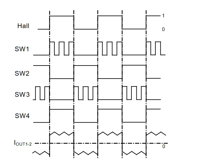
Figure 2: Single-Phase BLDC Motor Sensor versus Drive Timing
- Figure 2 shows an example of Hall sensor signals with respect to switch drive signals and armature current.
The armature current exhibits a saw tooth waveform due to PWM control. The applied voltage, switching frequency,
and the PWM duty cycle are three key parameters to determine the speed and the torque of the motor.
Conclusion:
- It is easily controlled with position feedback sensors and generally performs well, especially in speed/torque.
With these advantages, BLDC motor will spread to more applications.
- Moreover, with the development of sensorless technology, BLDC motor will become convenient or indispensable in
applications with environmental limitations.