Week -2
OBJECTIVE:
Create a situation where the switch is closed for 2 seconds and then released. Observe the physical movement of the plunger.
SIMULINK MODEL:
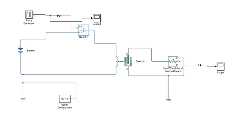
EXPLANATION:
- For the above circuit we need battery, pulse generater, switch, solenoid, ideal translational motion sensor and scope.
- Battery and pulse generator are connected to switch.
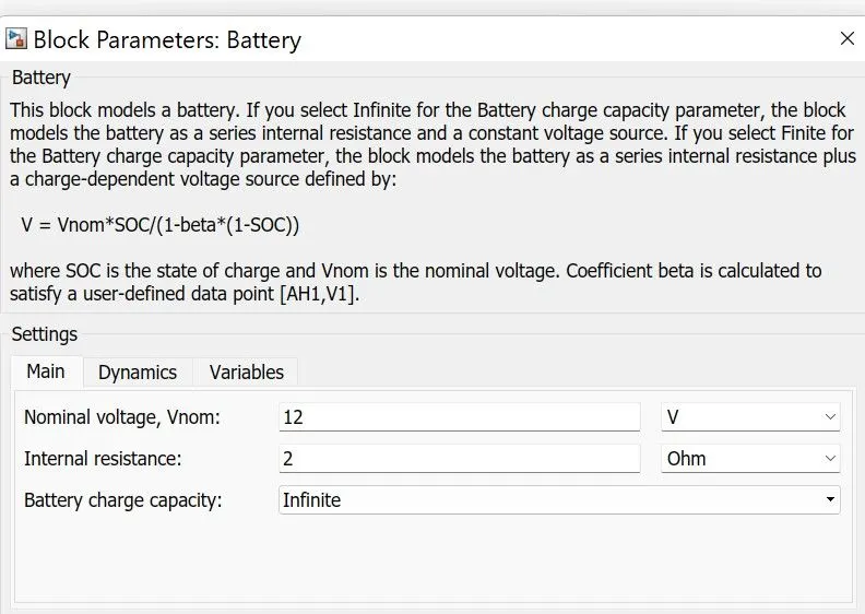
- Battery voltege is 12V with 2 ohms internal resistence.
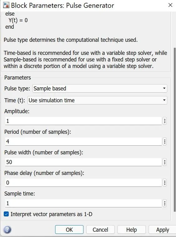
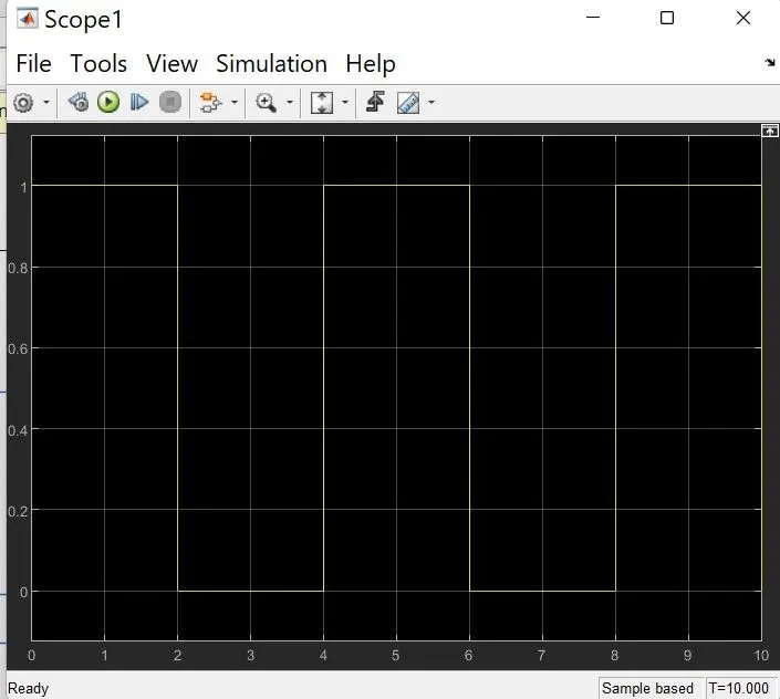
- Pulse generator parameters and output are shown below.
- The '+' terminal of solenoid is connected to switch and '-' terminal is connected to battery.
- R and C terminals of solenoid are connected to Ideal translational motion sensor to moniter the movement of the plunger.
- Output of sensor is connected to scope to plot the output graph.
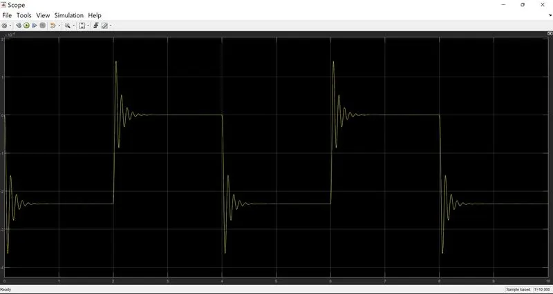
- Below graph shows the final output of the solenoid.
- It is clearly seen in the graph that the bell ON for 2 seconds and OFF for other 2 seconds.
OUTPUT GRAPH:
2.
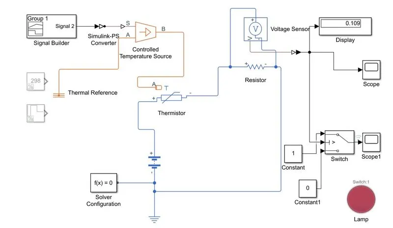
OBJECTIVE: To sense the temperature of a heater using thermistor and turn on/off a fan as per the given condition.
BLOCK DIAGRAM AND ITS COMPONENTS:
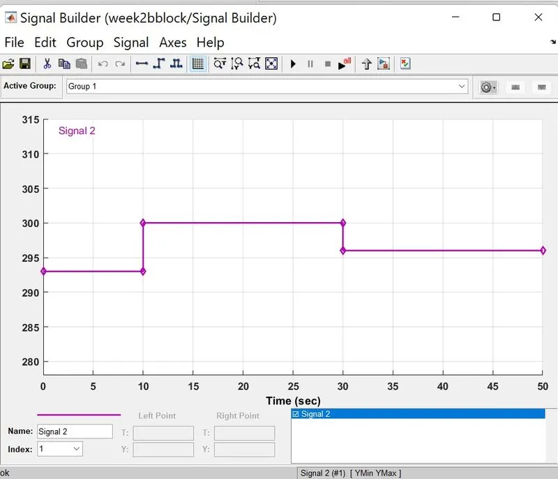
SIGNAL BUILDER BLOCK:
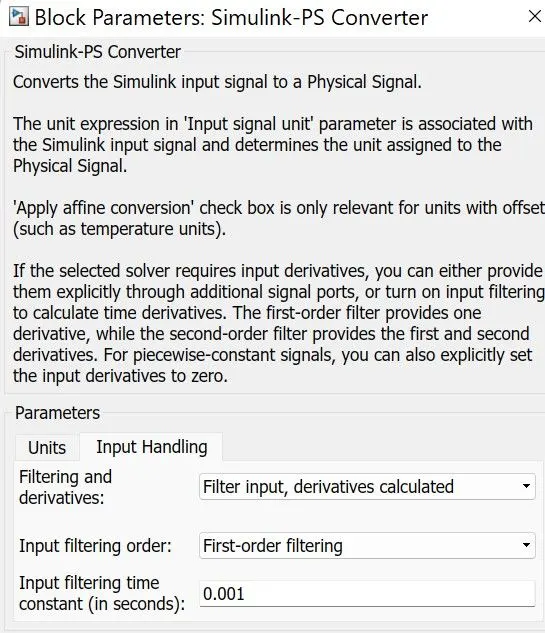
SIMULINK TO PS CONVERTER:
BATTERY BLOCK PARAMETERS:
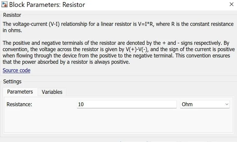
RESISTOR BLOCK PARAMETERS:
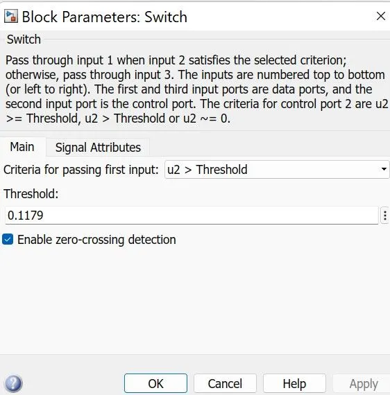
SWITCH BLOCK PARAMETERS:
- For switch we gave the threshold value 0.1179.
- Lamp is connected to switch.
- Input for switch is given from voltage sensor.
- It means above the threshold value the lamp is ON and Below the threshold value lamp is in OFF state.
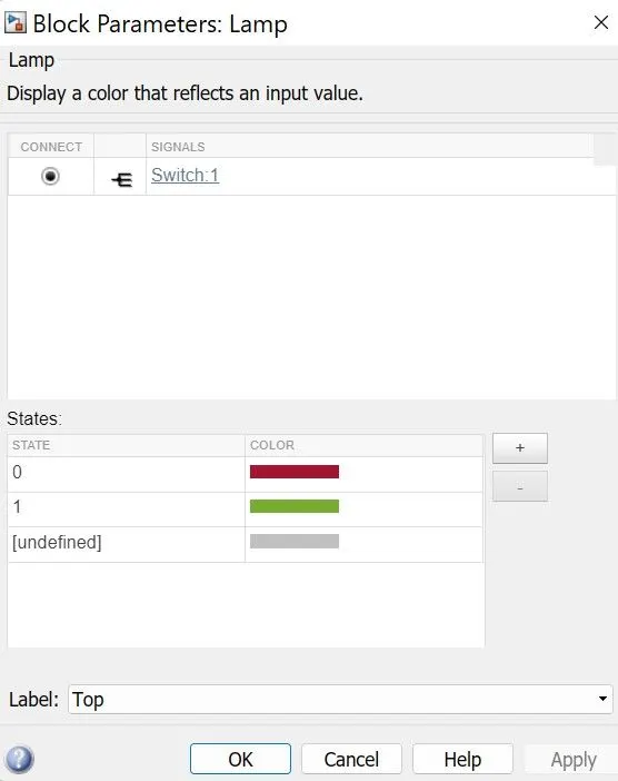
LAMP BLOCK:
We are using lamp in place of fan and lamp parameters are given in the block.
OUTPUT GRAPH:
Shows the turn on and turn off characteristics of lamp for different temperature conditions.
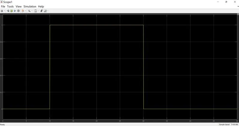
- 0 to 10 seconds the temperature is 293k and the lamp is in OFF state.
- 10 to 30 seconds the temperature is 300k and the lamp is in ON state.
- 30 to 50 seconds the temperature is 296k and the lamp is in OFF state.