Week-6 Challenge: EV Drivetrain
Working Principle of Chopper:
A chopper is a high speed ON/OFF switch. It connected source to load and disconnects the load from the source at a fast speed.
Figure below represents the simple circuit to show its working principle.
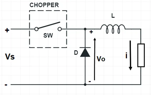
In this circuit, the switch SW is chopper. This switch can be made ON and OFF at a very high speed
In this circuit, the switch SW is chopper. This switch can be made ON and OFF at a very high speed. In this way, the load may be connected and disconnected from the supply source Vs. When the switch is ON, the load voltage is equal to the source voltage Vs and when the switch is OFF, load voltage becomes equal to ZERO. Thus, a chopped voltage across the load is obtained. The output voltage i.e. voltage across the load is shown in figure below.
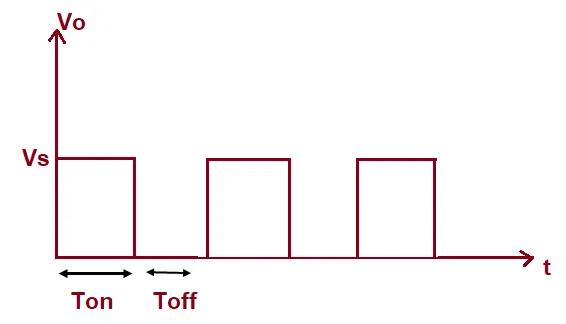
It should be noted here that, when the switch SW is made OFF, the load current finds its path through free wheeling diode D. Therefore, diode D acts as a short and hence the voltage across the load becomes zero. Inductor in the chopper is an essential thing. This inductor makes diode D forward biased when the switch SW is OFF.
It should also be noted that, even though the switch SW is made OFF, the load current doesn’t becomes ZERO. Rather, it flows through the free wheeling diode, inductor L and load. In fact, the load current is continuous as shown below.
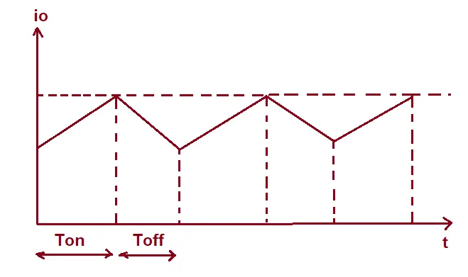
It may be seen from the above waveform of output current of chopper that, during ON time, the current rises whereas during OFF time, the load current io decays.
The time for which chopper connects the load from source is called ON time i.e. TON. Whereas, the time for which load is disconnects from source is called OFF time i.e. TOFF.
Duty Cycle:
Duty cycle of chopper is defined as the ratio of ON time to the total time period. It is denoted by symbol α. Total time period is the sum of ON and OFF time.
Duty Cycle = TON / (TON+TOFF)
Assuming (TON+TOFF) = T, duty cycle is given as below.
Duty Cycle, α = (TON / T)
Calculation of Output Voltage:
The average output voltage of chopper may be find from the output voltage waveform. It is clear from the o/p voltage waveform that, voltage Vo is available only for TON time period in the total time (TON+TOFF). Therefore, avergare ouput voltage Vo may be calculated as shown below.
Vo = TON Vs / (TON+TOFF)
But, TON / (TON+TOFF) = α
Hence,
Vo = αVs
Thus, the output voltage may be controlled by controlling the duty cycle. This duty cycle may be controlled in various ways which we will discuss in the next post. From the expression of ouput voltage, it is also clear that, the output voltage is independent of the load current.
The expression for chopper output voltage may also be written as below.
Vo = TON Vs / (TON+TOFF)
= Vs TON / T
Assuming 1/T = Chopping frequency
Vo = f Vs TON
We have different types of chopper:
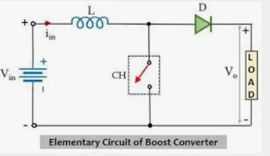
Step-up Chopper:(BOOST CONVERTER)
It is a kind of chopper in which the average DC output voltage is more than the source voltage. In this chopper, power flows from load to source and load contains a
source of emf and should be inductive.
Step-down Chopper:(BUCK CONVERTER)
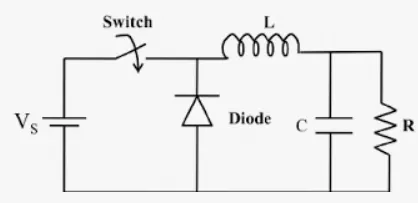
A chopper whose average DC output voltage is less than the source voltage is called step-down chopper. Power flows is always from source to load in this chopper.
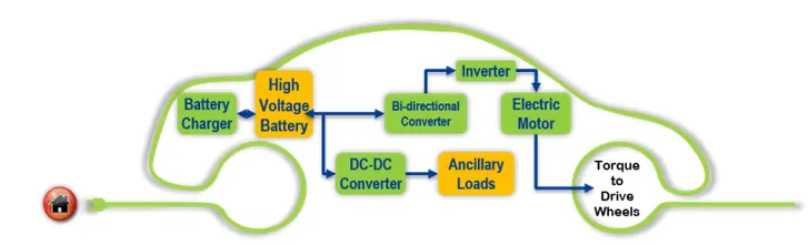
BUCK-BOOST CCONVERTER: It is used as both buck and boost based on requirement:
- Rectifier
- chopper
- Inverter
In all the above power converters we use semiconductor switches for example
- SCR
- GTO
- IGBT
- MOSFET
2.
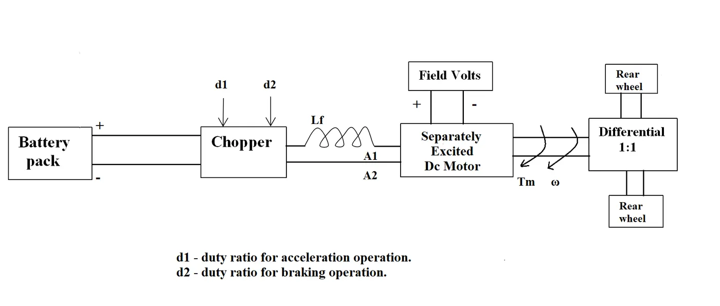
An Electric Vehicle's powertrain with 72V battery pack in shown in the diagram below. The duty ratio for acceleration operation is 'd1' and for the braking operation the duty ratio is 'd2'.
The other parameters of the electric vehicle is given below,
Motor and Controller Parameters:
Rated Armature voltage= 72 V
Rated armature current= 400 A
Ra= 0.5Ω, KΦ= 0.7 Volt second
Chopper Switching frequency= 400 Hz
The vehicle speed-torque characteristics are given by the below equation

What is EV steady state speed if duty cycle is 70%?
Solution:
Given data:
battery voltage V= 72 V
Duty ratio= 70%
Ra=0.5ohm
Kϕ= 0.7 V-sec
Chopper switching frequency = 400Hz
Tv = 24.7+(0.0051)ω^2
Output voltage = Vo
Vo= battery voltage(V)* duty cycle ratio = 72*0.70
Vo=50.4 V
vehicle Torque =
Where:
Tv is Vehicle torque(N-m)
Vo = vehicel output voltage
ω= Steady state speed of vehicle
Kϕ= motor constant
Ra = armature resistance
Now Substitute the values in the equation we get
T = [50.4*(0.7/0.5) - ω.(0.7^2/0.5)]
T = 70.56 - 0.98ω ---(1)
Tv = 24.7+0.0051.ω^2 ----(2)
Solving the above equations ,
We get quadratic equation
0.0051ω^2 + 0.98ω - 45.86 = 0
Solving the quadratic equation we get
ω = 38.23 rad/s and ω = -231.06 rad/s
We prefer positive speed of vehicle
Steady state speed of the vehicle is 38.23 rad/s
3. Develop a mathematical model of a DC Motor for the below equation using Simulink.
ω= V/Kϕ -Ra.T/Kϕ^2
assume
- V=72 V
- Kϕ=0.7 V/sec
- ra=0.3 ohm
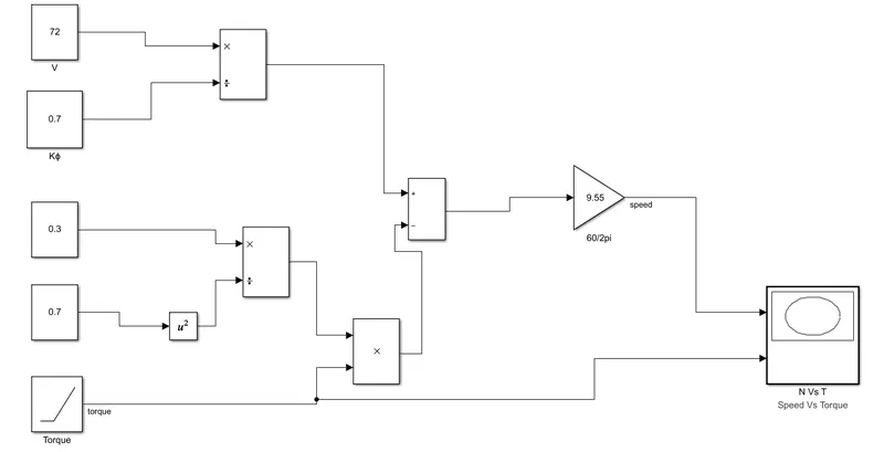
Explanation:
- Use Constant block for representing Voltage (V) ,Motor constant( Kϕ) and Duty cycle (d)
- Torque is given by ramp block.
- Step1: The V and Kϕ blocks are given to Division block where V/Kϕ value is calculated and result is given to adder block.
- Step2: Kϕ block is given to square block , the output and Ra block is connected to Division block where Ra/Kϕ^2 is calculated.
- Step3: The output from division block is connected to product block where the second input is Torque block(ramp). Here (Ra/Kϕ^2).T is calculated.
- Step4: The output from product block is connected to Adder block as the second input.
- Step5: Adder block inputs are set as "+ -" that means we are doing subtraction.
- Step6: Now we calculated " ω= V/Kϕ -Ra.T/Kϕ^2 " in rad. connect the output to gain block with (60/2*pi) = 9.55 to convert into RPM.
- Step7: Gain block and Torque blocks are connected to XY scope to plot the graph.
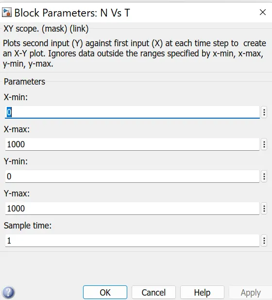
Result:
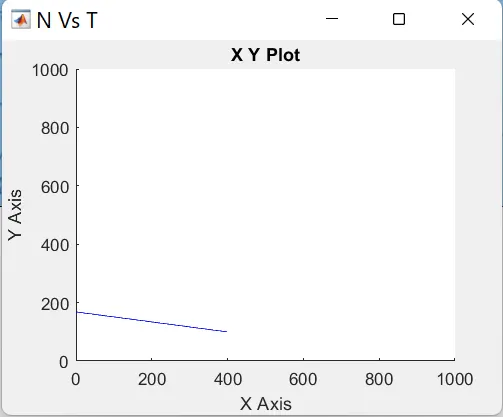
Observation:
- Speed on X-axis and Torque on Y-axis
- Speed in RPM Plotted on X axis.
- From the characteristics we understood that with increase in speed, Torque decreases
4.
Refer to the blog on below topic:
Induction Versus DC brushless motors by Wally Rippel, Tesla
Explain in brief about author’s perspective.
Objective: Explain the Wally Rippel, Tesla author's perspective of induction motor and dc brushless motor
- In the blog, Wally Rippel mentioned advantages and disadvantages of Induction motor and DC brushless motor.
- Author mentioned about Nikola Tesla and his invention.
- There is no one best engine type, rather there are different types of engines to suit personal requirements, such as price and performance.
- This is also true for electric vehicle drives.
- Now a days Lead acid batteries are replaced by Lithium-ion batteries.
- Author expained about two motors they are Brushless DC motor(BLDC) and Induction motor.
- He explained about the construction of Induction motor.
- He said unlike the DC brushless rotor, the induction rotor has no magnets – just stacked steel laminations with buried peripheral conductors that form a “shorted structure.” Currents flowing in the stator windings produce a rotating magnetic field that enters the rotor.
- Advantages of Induction motor over BLDC a 3-phase induction motor is connected to utility type 3-phase power, torque is produced at the outset; the motor has the ability to start under load. No inverter is needed.
- He says DC brush motors are replaced with DC brushless or Induction motors.
- The cost of permanent magnets is high which are used in BLDC.
- He mentioned it is difficult to control the field of ferrow magnets.
- The contactor controllers are replaced with modulating inverters.
- He mentioned brushless motors are useless motors without the inverter.
- He says Induction motor can not operate with dc supply
Conclusion:
Author says "STILL NO WINNER" and also also commented that Brushless motors will dominate in the hybrid and coming plug-in hybrid markets.
Induction Motors will in high performance pure elctric vehicles.
we notice that author mentioned the future is golden era where induction and Brushless Dc motors work side by side.