Project
AIM:
To study and analyse the BAJA All Terrain Vehicle(ATV)Cmodel using Simulink and
compare between different models.
OBJECTIVES:
- To Prepare a technical report explaining the functons of the subsystems & blocks used for preparing the model.
- To explain in detail all the differences between all the five models provided
- To understand and comment on the results.
TYPES OF MODELS :
- BAJA ATV model without Dashboard(cvtModel)
- BAJA ATV model - Data Extraction(cvtModel_data)
- BAJA ATV model with Dashboard(cvtModel_dashboard)
- BAJA ATV model- Mapped Lookup Table with Dashboard(cvtModel_dashboard_mapped)
- BAJA ATV model-Mapped lookup table with Dashboard(cvtmodel_dashboard_mapped)
Introduction:
ALL TERRAIN VEHICLE:
All terrain vehicle is defined as a motorized off highway vehicle designed to travel on four low-pressure or non-pnuematic tires, having a seat designed to be straddled by the operator and handlebars
for steering control.
BAJA SAE:
Baja SAE is an collegiate design series competition run by the Society of automotive engineers(SAE international).
Continuously Variable Transmission (CVT):
A CVT ia an automatic transmission that can change seamlessly through a continuous range of gear ratios. This contrasts with other transmissions that provide a limited number of gear ratios in fixed steps.
The flexibility of CVT with suitable control may allow the engine to operate at a constant RPM while the vehicle moves at varying speeds.
Main and critical blocks used:
Generic Engine Block:
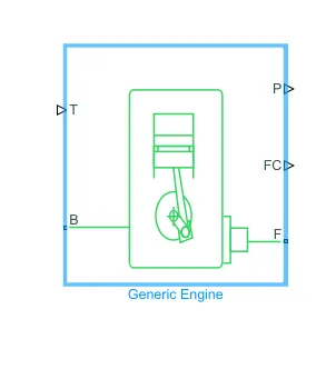
The generic engine block represents a general internal combustion engine. Engine types include spark ignition and diesel. Speed-power and speed-torque parameterizations are provided.
A throttle physical signal input specifies the normalized engine torque. Optional dynamic parameters include crankshaft inertia and response time lag. A physiacal signal port outputs engine fuel
consumption model. Optional speed and redline controllers prevent engine stall and enable cruise control.
Main ports:
- B- Rotational Conserving Port: representing the Engine Block(should be connected to rotational motion reference)
- F- Rotational Conserving port: Representing the Engine crankshaft.
- T- Physical signal input port: specifying the normalised engine throttle level
- P- Physical signal output port: reporting the instantaneous engine power, in W
- FC- Physical signal output port: reporting the fuel consumption rate, in kg/s
Simple Gear:
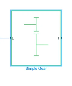
The simple Gear block represents a geaarbox that constrains the connected driveline axes of the base gear, B, and the follower gear, F, to corotate with fixed ratio that is specified.
The follower-base gear ratio is
gFB = rf/rB = NF/NB
Main Ports:
B - Base: Rotational mechanical conserving port assosiated with the base or input shaft.
F - Follower: Rotational mechanical conserving port assosiated with the follower, or output shaft.
Variable Ratio Transmission block:
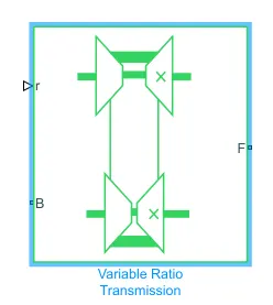
The Variable Ratio Transmission block represents a gearbox that dynamically transfers motion and torque between the two connected driveshaft axes , asse and follower.
Ignoring the dynamics of transmission compliance, the driveshafts are constrained to corotate with a Variable Gear Ratio control that you control. You can choose whether the follower axis rotates
in the same or opposite direction as the base axis. If they rotate in opposite signs.
Transmission compliance introduces internal time delay between the axis motions. Therefore, unlike a gear, a variable transmission does not act as a kinematic constraint.
You can also control torque loss caused by transmission and viscous losses.
Main Ports:
1. B-Base Pully or Drive Pulley
2. F- Follower Pulley Or Driven Pulley
3. r- Variable Transmission Ratio(input)
Variable Body block:
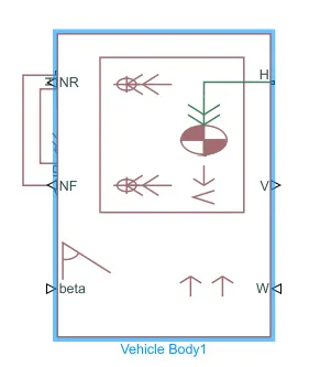
BAJA ATV MODEL WITHOUT DASHBOARD(cvt model):
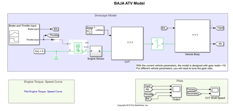
Main Model:
Steps:
- The throttle signal is generated by signal builder block and given as input to generic engine.
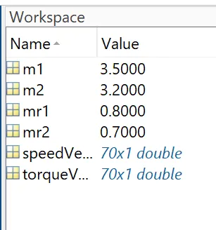
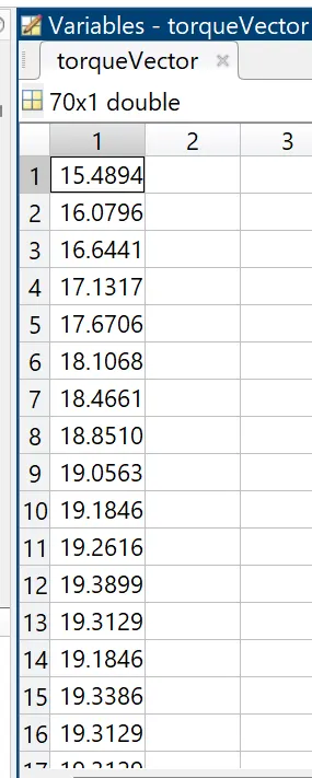
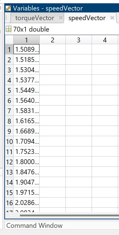
- The torque and speed vector are taken from matlab workspace.
- The engine will generate the output rpm which can be taken from the crankshaft output. This speed will be given to the Ideal Rotational Motion Sensor to sense the output rpm.
- The same output speed will be given to a simple gear mechanism to reduce the speed Where the ratio is 4.
- Then the output speed From Gear reducer will be given to the Variable Ratio Transmission block(CVT).
- The CVT ratio is given provided to the vehicle ratio transmission(CVT) block through Signal Builder.
- The Speed is Controlled by the cvt ratios and the controlled output speed is given to vehicle axle.
- The brake signal is generated by the signal builder and it is given to vehicle body for applying the brake to axle.
- The power from CVT is given to axle and the vehicle body for furthur analysis.
Input Signals:
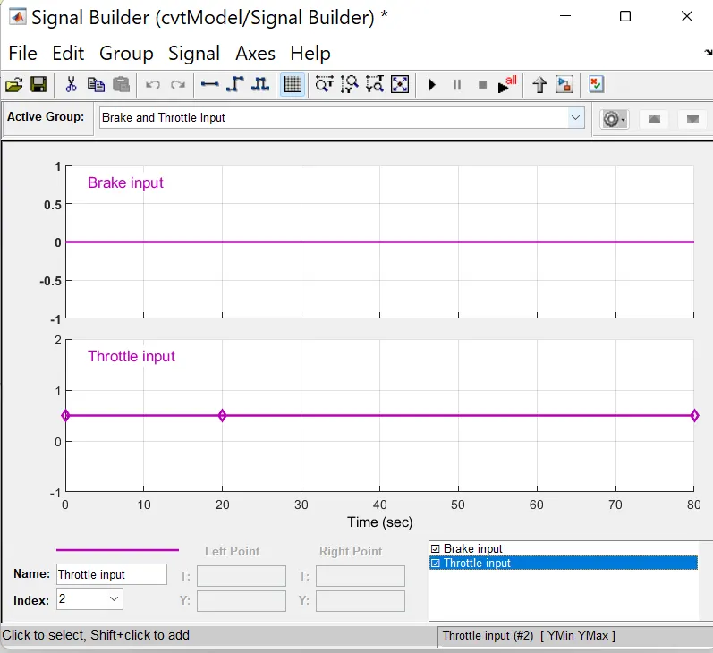
The Brake input remains zero through the whole simulation.
The Torque And Speed Matlab workspace input:
CVT Ratio input:
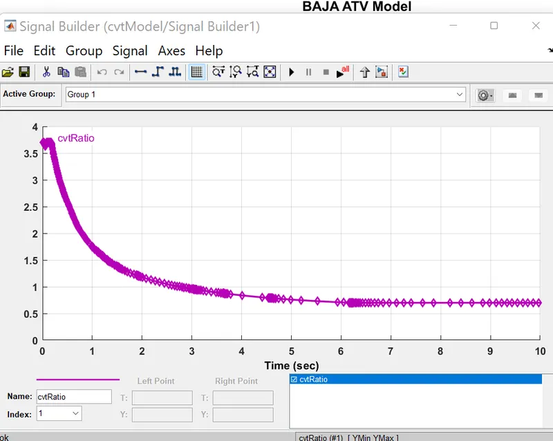
CVT Ratio starts at 3.5 then 5sec it gradually reduces until it reaches 0.8 At 6th second and it remains so till the end of the simulation.
ENGINE SENSOR SUB-BLOCK:
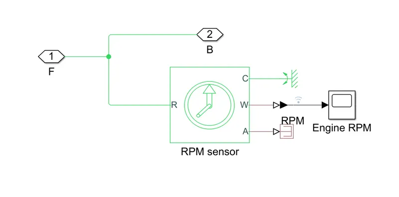
THis sub block measure engine rotational speed as it takes the output of the engine as its input and output engien rpm.
CVT sub block:
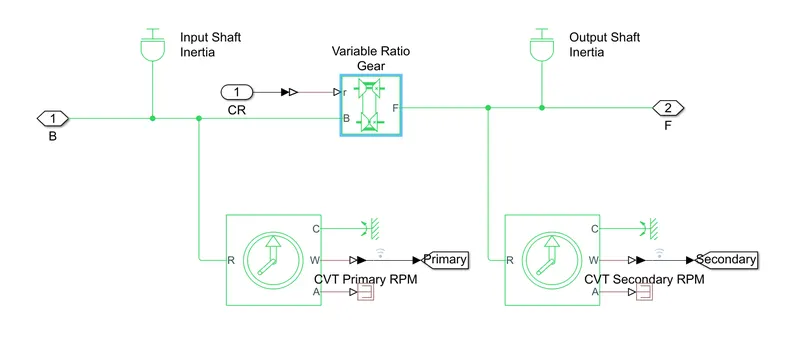
The CVT subblock provides the input and the output shafts of the cvt with inertia, and measure the input shaft rpm and the output shaft rpm.
Vehicle Body subblock:
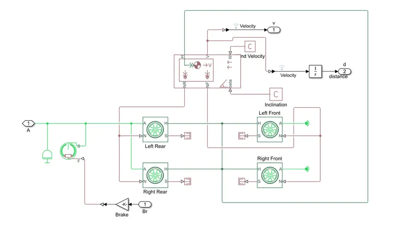
The model shows that the vehicle is rear wheel drive as the output from the gearbox is given to the rear axle. then an inertia is added to simulate axle inertia.
Results:
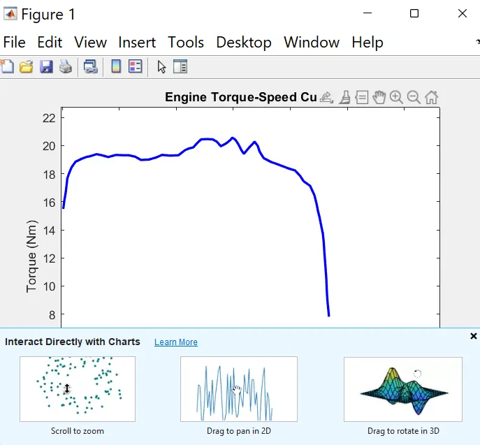
Observation: The Torque and speed are given from the matlab workspace window to the generic engine block to generate the output RPM accordingly.
The plot behaviour is generric to all ICE.
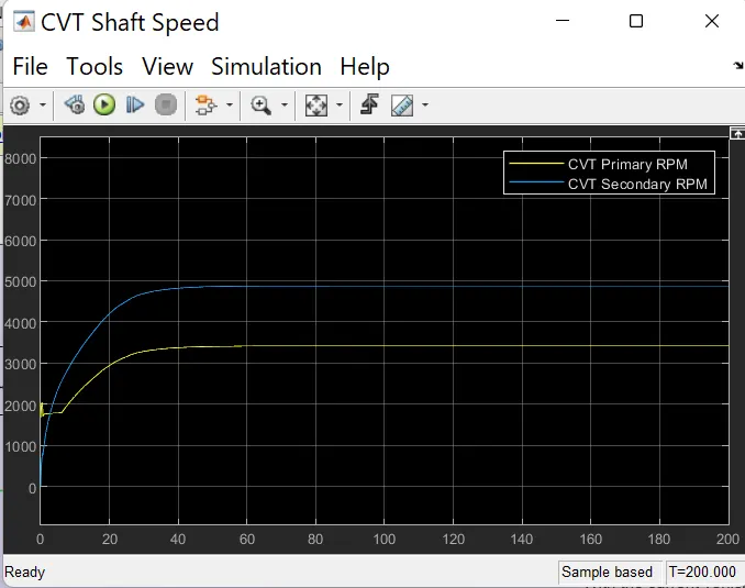
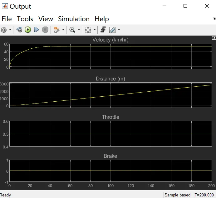
Observation from the Results:
- The engine RPM generated to the throttle, speed and torque inputs.
- In the above graph we see CVT primary RPM and secondary RPM data .
- In the next output graph we see velocity graph. The slowly rrises upto 55Kmph and is constant for remaining time.
- The distance travelled is increasing constantly with respect to time.
- From the graph we see the brakes are not applied during the driving cycle and the throttle with constant 0.5 value.