Week - 4
1. In washing machine stateflow model, We take two inputs as power snd water. The output is each stage but here we use the finish block for output.
So We require both power and water to be ON then all the other process will take place (i.e) Soaking, washing, rinsing & drying. If we give power and water equal to 1, then output will be zero. If even anyone of the power or water is zero, the the desired output is not achived.
Each process has some defined time according to the questions. So take the simulation time as 500sec.
2. In Gear shift model, there is range of speed for each gear. So the speed assigned should be such that as user defined. For that purpose we use a slider to vary the speed.
Here we go for chart model (i.e) control logic bases stateflow model. We use 2 symbols in it as Speed and G. If speed changes g also changes. We give a block such that above 15,25,40,60 we should shift the gear to 2,3,4,5 respectively. So Speed is a input port but G is the output port. Speed and G has only one port. Initially, It should be in first gear. We will provide a constant at input to view the speed given by the user. Output have a display used the see the gear that have been changed to. For each respective Gear, their repective lamp starts to blow.
.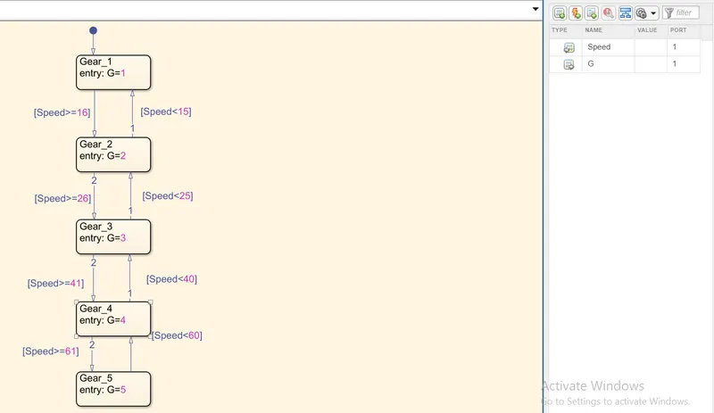
Above shown fig is the chart used and All the output as each speed range is also attached.