Project 2 Adaptive Cruise Control
daptive cruise control (ACC) is a system designed to help vehicles maintain a safe following distance and stay within the speed limit. This system adjusts a car's speed automatically so drivers don't have to.
Adaptive cruise control is one of 20 terms used to describe its functions so that you might see adaptive cruise control as the following in advertisements and vehicle descriptions:
- Active cruise control
- Dynamic cruise control
- Radar cruise control
- Automatic cruise control
- Intelligent cruise control
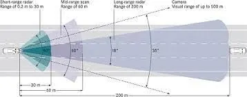
ACC functions by sensory technology installed within vehicles such as cameras, lasers, and radar equipment, which creates an idea of how close one car is to another, or other objects on the roadway. For this reason, ACC is the basis for future car intelligence.
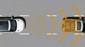
These sensory technologies allow the car to detect and warn the driver about potential forward collisions. When this happens, red lights begin to flash, and the phrase 'brake now!' appears on the dashboard to help the driver slow down. There might also be an audible warning.
Advantages of Adaptive Cruise Control
Some key advantages of ACC mentioned by MyCarDoesWhat.org include an increase in road safety, as cars with this technology will keep the adequate spacing between them and other vehicles. These space-mindful features will also help prevent accidents that result from an obstructed view or close following distance. Similarly, ACC will help maximize traffic flow because of its spatial awareness. As a driver, you don't have to worry about your speed, and instead, you can focus on what is going on around you.
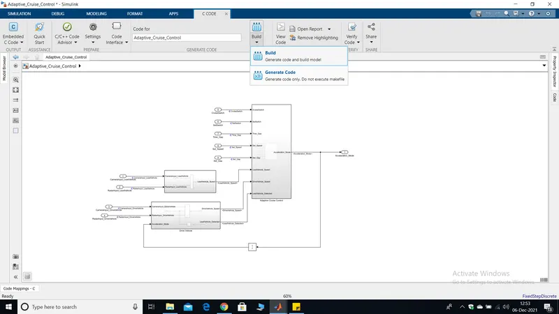
The total block model is:
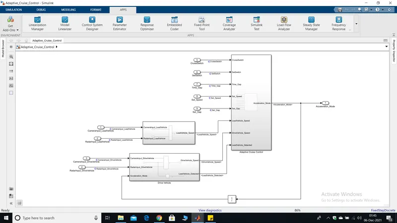
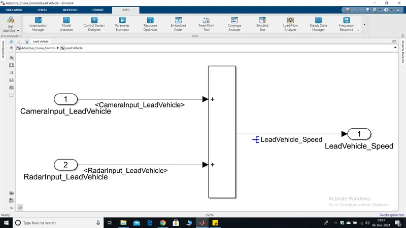
Requirement 1– Lead Vehicle:
- Lead Vehicle is a vehicle which is driving in the road ahead of our drive vehicle. Two input signals (Signal Name: CameraInput_LeadVehicle & RadarInput_LeadVehicle).
- Ideally sensor fusion techniques will be deployed to process & analyze data from camera & radar. For complexity reasons, let’s not adapt to any such algorithms.
- We can simply add both the radar & camera inputs & the corresponding output is read as Speed profile output (Signal Name: LeadVehicle_Speed).
- Speed data of the lead vehicle is critical in implementing the Adaptive Cruise Control algorithm.
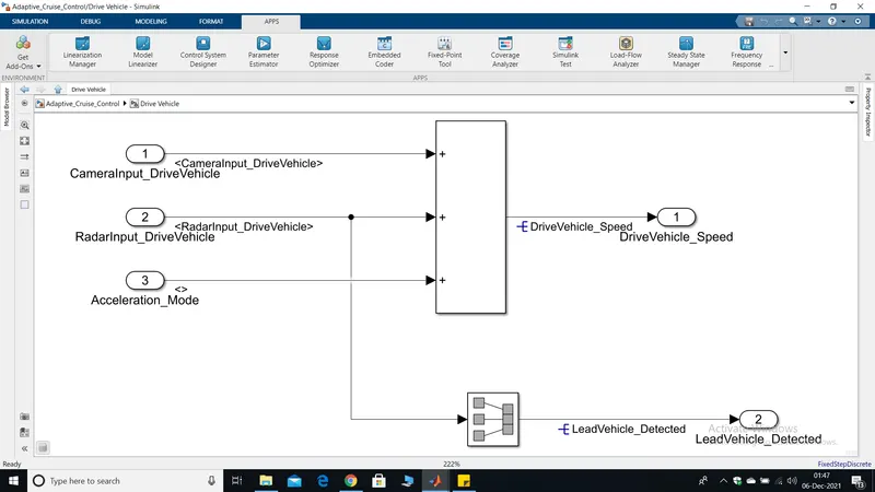
Requirement 2 – Drive Vehicle:
- Drive Vehicle is the vehicle driven by the user & this is the vehicle which has ACC algorithm in it.
- Like the Lead Vehicle, Drive Vehicle algorithm also has 2 input signals (Signal Name: CameraInput_DriveVehicle, RadarInput_DriveVehicle) & one signal coming as an Input to this subsystem (Signal Name: Acceleration_Mode) – three inputs into this requirement in total.
- Like the above requirement, sensor fusion techniques will also be deployed here, for complexity reasons we are ignoring them.
- Two output signals come from this subsystem (Signal Name: DriveVehicle_Speed & LeadVehicle_Detected).
- Signal DriveVehicle_Speed is summation of three input signals mentioned above & LeadVehicle_Detected is renamed from Input Signal RadarInput_DriveVehicle by mere use of Signal Conversion block.
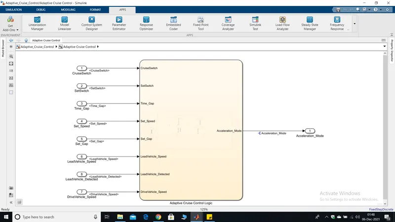
Requirement 3 – Adaptive Cruise Control Algorithm:
- Adaptive Cruise Control feature has 3 major modes of operation: OFF Mode, STANDBY Mode & ON Mode. This particular requirement has to be implemented as state machine logic in Simulink.
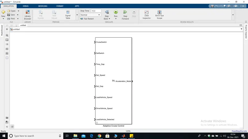
- The input signals to this state machine system are (Signal Name: Time_Gap, Set_Speed, Set_Gap, CruiseSwitch, SetSwitch).
- Also, the output signals (Signal Name: DriveVehicle_Speed & LeadVehicle_Detected) from requirement-2 is fed back as an input signal into this state machine block.
- Additionally, output signal (Signal Name: LeadVehicle_Speed) from requirement-1 is given as an input signal to this state machine block as well.
- Output from this subsystem is a signal (Signal Name: Acceleration_Mode) which governs the vehicular speed of the drive vehicle which automatically adjusts its speed & velocity to match the lead vehicle.
Requirement 3a – ACC OFF MODE state logic:
- This is the default state inside state machine logic. Output signal Acceleration_Mode is at value 0 in this state.
- This state is governed by input signal CruiseSwitch.
- If CruiseSwitch is equal to 1, state ACC STANDBY mode will get activated. If CruiseSwitch is equal to 0, state ACC OFF mode will get activated, from either ACC ON mode or ACC STANDBY mode
Requirement 3b – ACC STANDBY MODE state logic:
- This is the second activated state inside state machine logic. Output signal Acceleration_Mode is at value 1 in this state.
- This state is governed by both input signals CruiseSwitch & SetSwitch.
- If CruiseSwitch is equal to 1, state ACC STANDBY mode will get activated. If CruiseSwitch is equal to 0, state ACC OFF mode will get activated, from either ACC ON mode or ACC STANDBY mode
- If SetSwitch is equal to 1, state ACC ON mode will get activated. If SetSwitch is equal to 0, state ACC STANDBY mode will get activated.
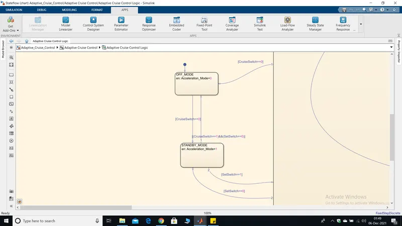
ON MODE chart is as follows:

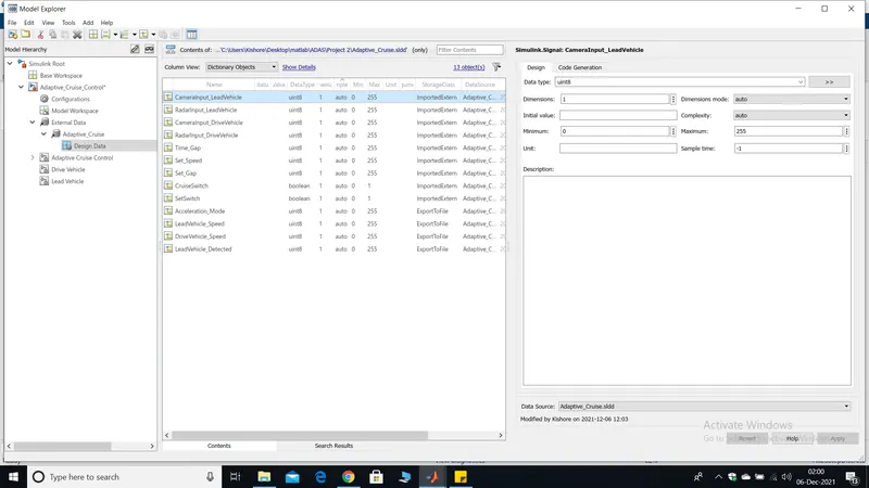
SLDD data is as:
Signals & Calibration Data List:
|
Signal / Calibration Name |
Signal Type |
Data Type |
Dimension |
Min |
Max |
Initial Value |
Units |
|
CameraInput_LeadVehicle |
Input |
Uint8 |
1 |
0 |
255 |
- |
- |
|
RadarInput_LeadVehicle |
Input |
Uint8 |
1 |
0 |
255 |
- |
- |
|
CameraInput_DriveVehicle |
Input |
Uint8 |
1 |
0 |
255 |
- |
- |
|
RadarInput_DriveVehicle |
Input |
Uint8 |
1 |
0 |
255 |
- |
- |
|
Time_Gap |
Input |
Uint8 |
1 |
0 |
255 |
- |
- |
|
Set_Speed |
Input |
Uint8 |
1 |
0 |
255 |
- |
- |
|
Set_Gap |
Input |
Uint8 |
1 |
0 |
255 |
- |
- |
|
CruiseSwitch |
Input |
Boolean |
1 |
0 |
1 |
- |
- |
|
SetSwitch |
Input |
Boolean |
1 |
0 |
1 |
- |
- |
|
Acceleration_Mode |
Output |
Uint8 |
1 |
0 |
255 |
- |
- |
|
LeadVehicle_Speed |
Output |
Uint8 |
1 |
0 |
255 |
- |
- |
|
DriveVehicle_Speed |
Output |
Uint8 |
1 |
0 |
255 |
- |
- |
|
LeadVehicle_Detected |
Output |
Uint8 |
1 |
0 |
255 |
- |
- |
SIL model is as follows:
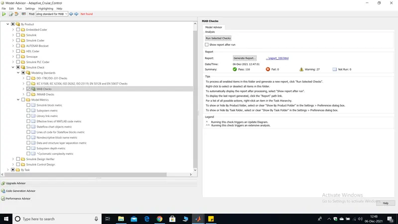
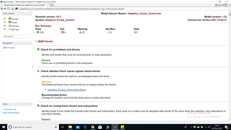
Model Advisory Report:
By running the model advisory tool, we can get zero error based on the MAB checks on modelling standards.
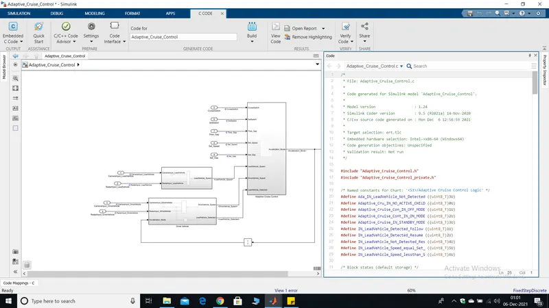
CODE GENERATION :