Week 3: Flow over a backward facing step
Aim:
To setup the case in CONVERGE studdio.
Objective:
Once you have watched the video, setup the case in CONVERGE
Once you have the base setup ready, run the case for three different base mesh sizes
- dx = dy = dz =2e-3m
- dx = dy = dz =1.5e-3m
- dx = dy = dz =1.0e-3m (If this is too much for your PC, use 1.2e-3m)
-
Contents to be shown in the report:
1. Show the mesh (i.e surface with edges) for all the 3 base mesh sizes
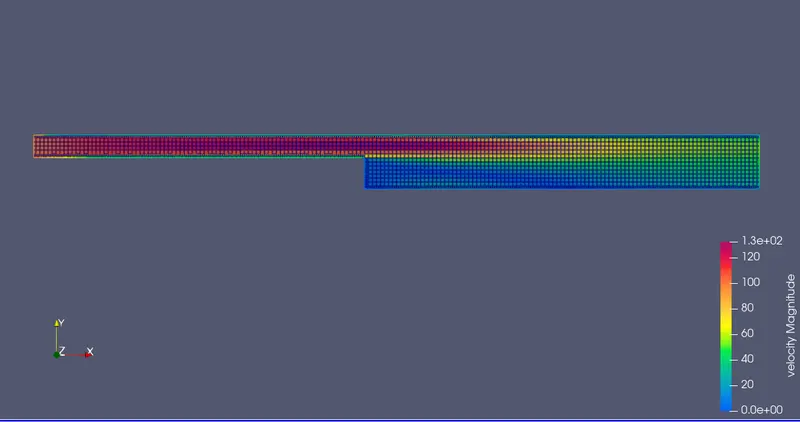
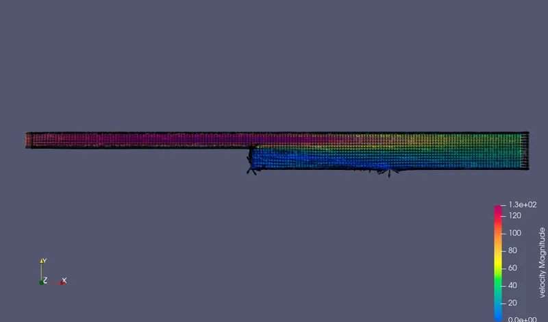
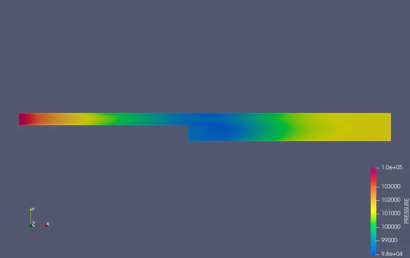
2.Show pressure and velocity contours
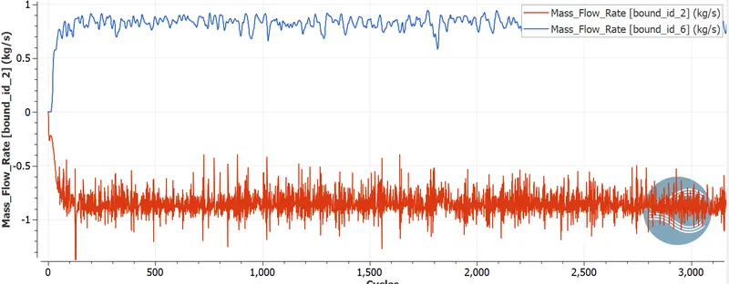
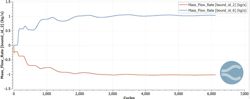
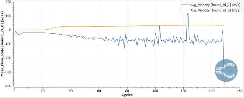
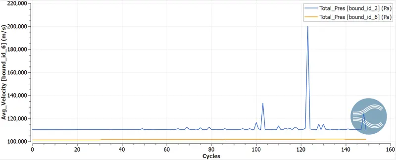
3. Show the plots of velocity, pressure, mass flow rate and total cell count for all the 3 base mesh sizes
4. Also explain where and why separation is taking place in detail.
Make sure you make your project public. Once you are done, paste the link to your project here.
Create animations and upload on Youtube and provide the youtube link in the report.
Theory:
Intorduction:
Fully developed flow enters the domain from left. once the flow reaches the step, thanks to growth of flow channel, pressure gradient exists, it detaches and a recirculation zone is created. A turbulent physical phenomenon encounters a unexpected back step, inflicting flow separation. Later the flow eventually reattaches to the lowest wall.
Backward-Facing Step (BFS) flow is one representative model for separation flows, which might be wide seen in mechanics flows (airfoil, spoiler, high attack angle process), engine flows, condensers, vehicles (cars, boat), heat transfer systems, and even the flow around buildings, etc. The flow separation once a straightforward stage can introduce separation bubble formation, evolution and re-attachment method, that relies on the Backward Facing Step geometric style, the water and outlet conditions, turbulent intensity, similarly as heat transfer conditions. it's shown that the step size (duct growth ratio) can outline the fundamental re-circulation and re-attachment method.
It is a basic model involving the foremost necessary feature of a separated flow –a free shear flow separation, vortex generation and reattachment.A backward step flow includes Associate in Nursing flow of uniform speed,laminar or turbulent from a channel to a tread the either sides with a step height of h .The flow fluid is split into four regions particularly separated Shear layer ,the recirculation region beneath the shear layer,the reattachment region, and therefore the recovered physical phenomenon.
Flow with separation and reattachment has long been a subject matter of basic fluid dynamics analysis. The presence of a separated flow, at the side of a reattaching flow, provides rise to enlarged unsteadiness, pressure fluctuations, structure vibrations and noise, because it additionally exhibits Associate in Nursing unsteady structure with an outsized scale vortex within the separated shear layer and low-frequency motion round the reattachment region with fluctuation of an instant reattachment purpose.
Turbulent flow over a backward-facing step is one in every of the classical tests to validate turbulence models in CFD. within the gift work, steady-state flow over a backward-facing step was simulated exploitation Converge with the Renormalization-group (RNG) k-ε model to account for turbulent consistency
Turbulent flows occur in a very kind of industrial issues. A flow is termed as turbulent once the mechanical phenomenon forces of the fluid area unit bigger than the viscous forces leading to chaotic fluctuations within the flow.
Importance of Backward Facing Step drawback
Separation and reattachment of turbulent flows occur in several sensible engineering applications. it's seen each in internal flow systems like diffusers, combustors and channels with unforeseen expansions, and in external flows like flow around aerofoil and building. In these things, the flow experiences Associate in Nursing adverse pressure gradient, that causes the physical phenomenon to break away the solid surface. The flow afterward reattaches downstream forming a recirculation bubble. The presence of a separated flow, at the side of a reattaching flow, provides rise to enlarged unsteadiness, pressure fluctuations which can cause structure vibrations and noise.CASE study for the model:
Application sort – Time based mostly
The flow is general flow that contains the air as a fabric.
Air contains a Species mixture of O2 and N2 which can flow through the desired pure mathematics.
Global Transport Parameters the Prandtl variety is zero.9 and therefore the statesman variety is zero.78.
Simulation Parameters:
In the Run Parameter: problem solver we tend to used is Steady state and therefore the simulation mode = Full hydraulics within the mic state we tend to change the problem solver Momentum, Solve Species and Steady state Monitor.
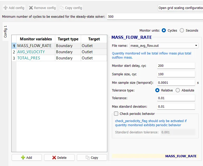
In the Steady State Monitor, we tend to keep the minimum variety of Cycles to be execute for Steady State problem solver is 15000 and that we add the monitor variables of Mass rate and average speed.
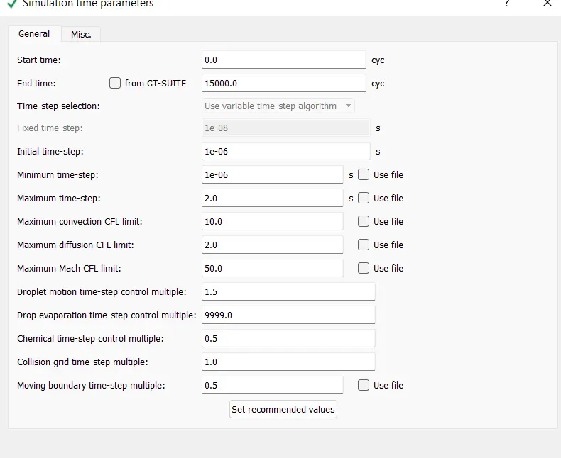
In Simulation time Parameters we tend to set the values for begin time as zero cycles and finish time 15000 cycles and therefore the initial and Minimum time setup for 1e-9 and remaining values square measure place to default
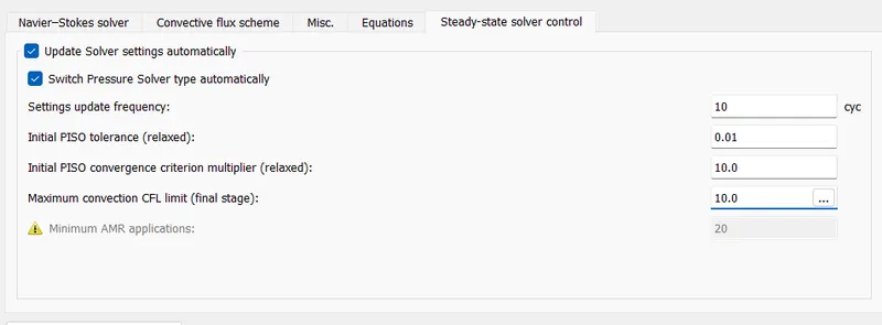
In the problem solver Parameters, the Navier stock equation ought to be Pressure based mostly problem solver and remaining ought to be default.
The number of cycles for the 2e-4 mesh, 1.5e-4 and 1.2e-4 is 15000 so as to converge the answer.
Initialization and Boundary Conditions:
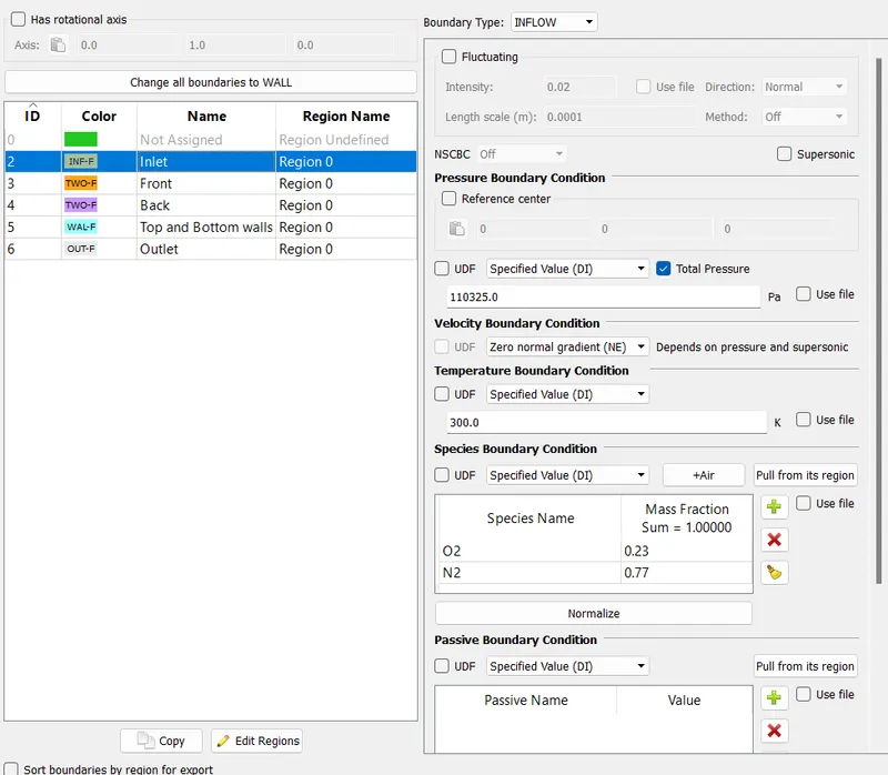
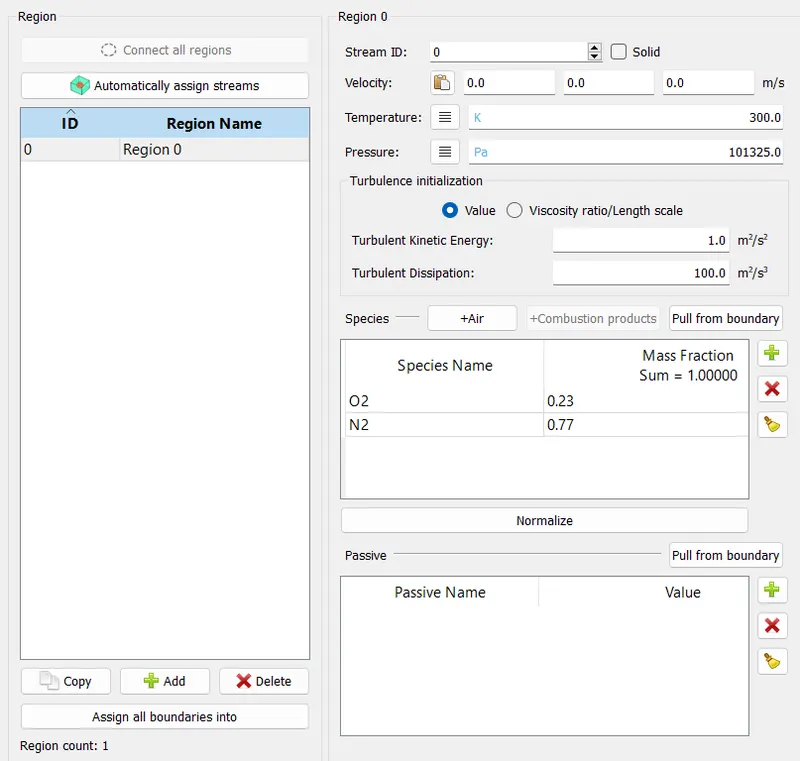
In the formatting region modification the name of the Region as a volumetrical region and therefore the values assigned for the temperature and pressure is 300k and 101325.0 Pascal and add the species O2 and N2 with the mole fraction of zero.23 and 0.77.
The pressure at the body of water is 110325 Pascal and therefore the temperature ought to be three hundred k and therefore the boundary sort is influx
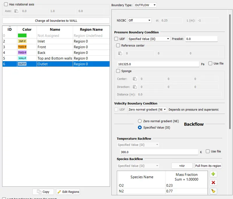
The pressure at the outlet is 101325 Pascal and therefore the temperature ought to be three hundred k and therefore the boundary sort is OUTFLOW.
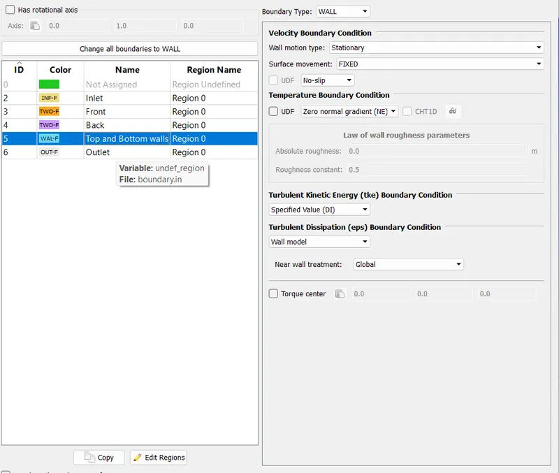
For the highest and Bottom boundary ought to be the wall sort with a Law of wall precondition and temperature ought to be 300k.
The front_2d and back_2d and therefore the boundary sort is second wall.
The number of cycles for the 2e-4 mesh, 1.5e-4 and 1.2e-4 is 15000 so as to converge the answer.
Physical Models:
In the physical models change the Turbulence Modelling and therefore the problem solver ought to be selected as RNG K-e and place the remaining values as a default.
Grid Control:
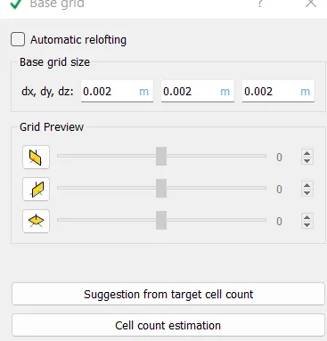
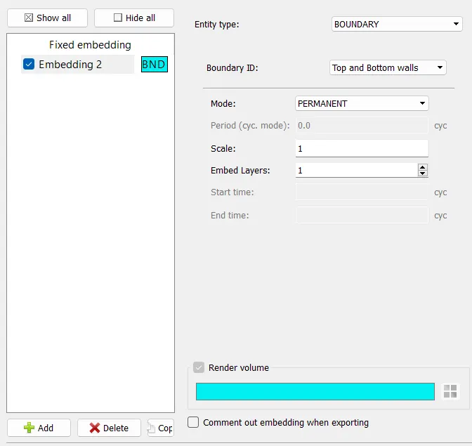
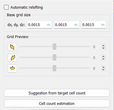
In the Grid management change the fastened Embedding and Base grid
Enter the bottom grid values then visit the fastened Embedding add the
Entity type=Boundary
Boundary ID=Top and Bottom
Mode =Permanent
Scale=1
Embedded layers=1
After entered all the values click on apply.
Output and Post Processing:
Post variable choice and Output files square measure the default values.
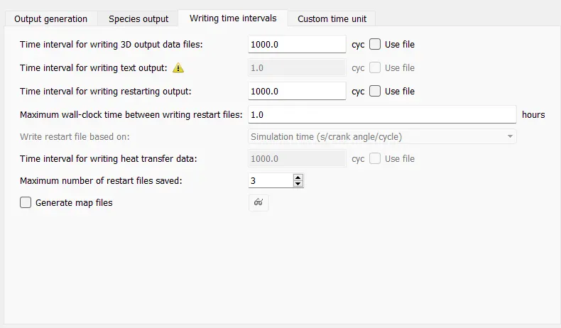
In the output files we've given quantity to jot down the output data=1000 cycles, therefore the outputs of the simulation files be hold on once a thousand cycles.
Post-Processing:
I have done the post process of the results for all 3 cases victimization the converge studio and paraview. Post process is really utilized in order to induce the required Output by running the simulationConverge studio geometry modal:
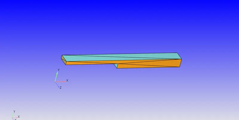
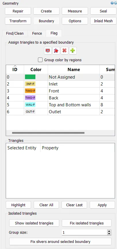
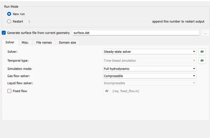
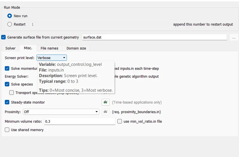
RESULTS:
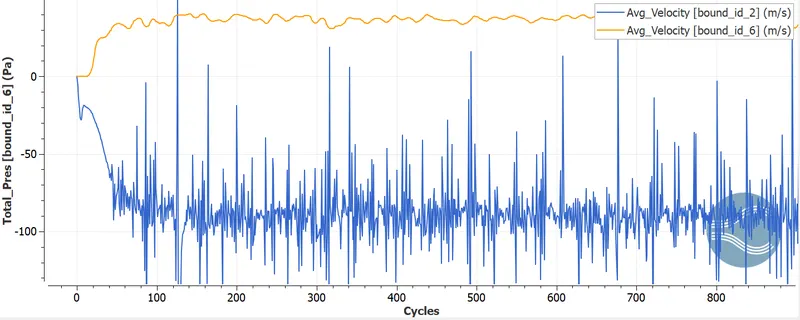
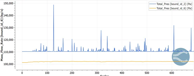
CASE 2: size grid:
1.5e-3m
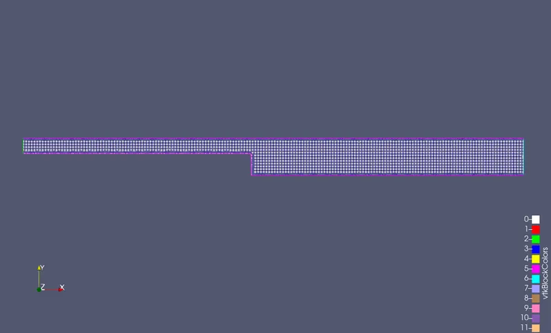
RESULTS:
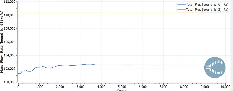
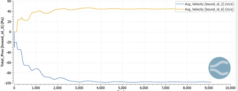
CASE 3:
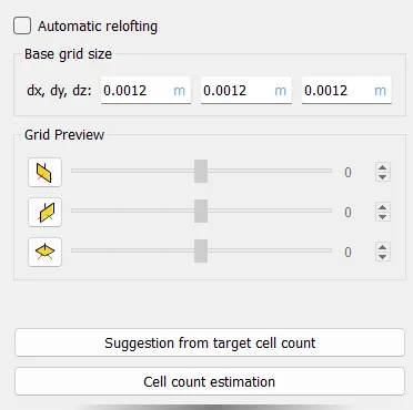
grid size: 1.2e-3
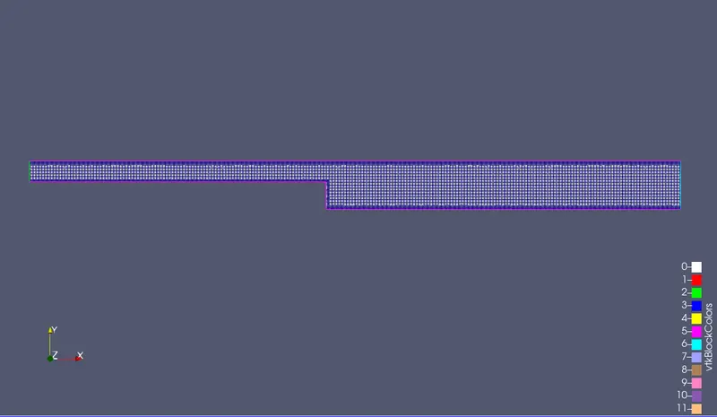
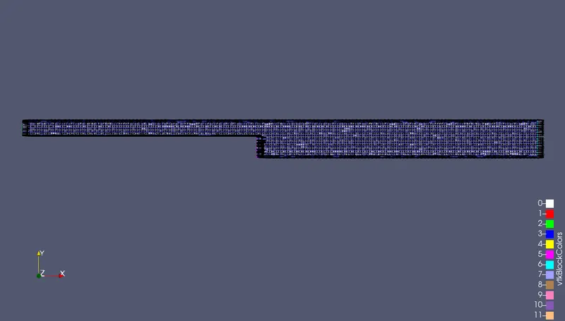
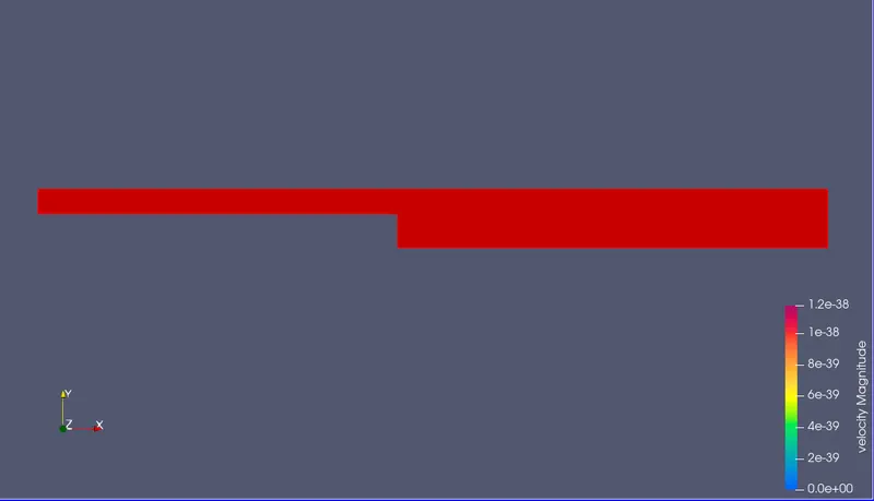
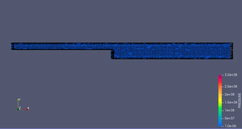
RESULTS:
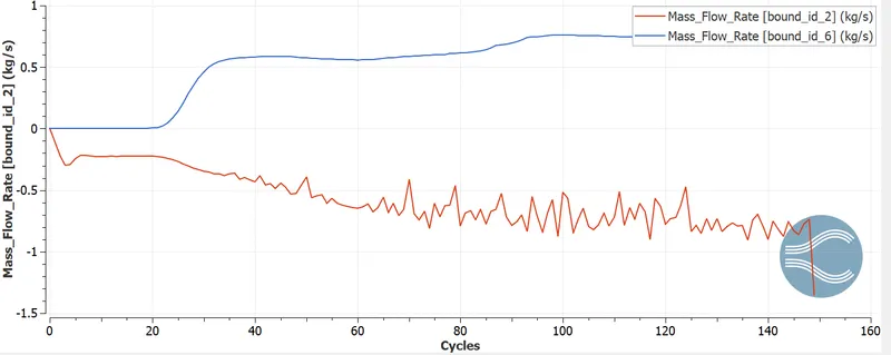
Conclusion:
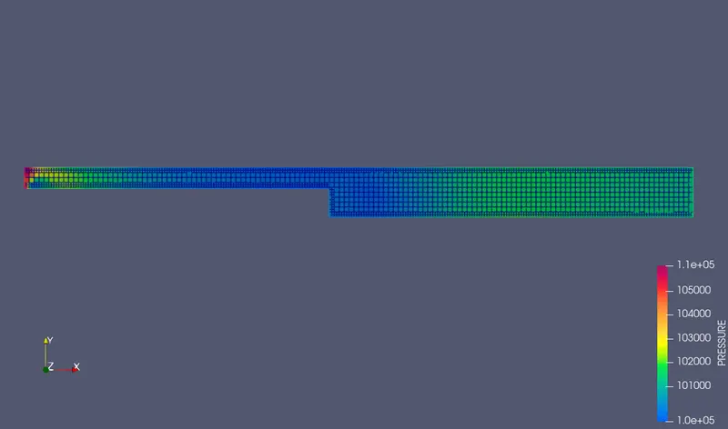
- From the on top of pictures we are able to observe the final characteristics of the flow begins wherever the upstream physical phenomenon develops and therefore the pressure gradient is developed into skinny shear layer.
The turbulent structures within the shear layer catches the irrotational fluid from the non flow and this causes from the low rate recirculation within the region.
The primary vertex is accured at the middle from the step and therefore the secondary vertex is made at the corner of the step and therefore the pressure gradient forms the shear layer curves(in the speed image the sky blue color) goes down the wall and touches the wall.Some of the streams flow right and forms the recirculation region and a few them goes right and reaches the outlet.
The reattachemnt length is that the distance between the step and therefore the reattachment purpose.After the each recirculation of flow happens it flows towards the outflow direction so as to discharge from the channel.
Thus the all regions square measure shaped in our simulation i.e. Shear layer,Primary recirculation,Secondray recirculation,Reattachment zone.This can be clearly discovered within the case three rate profile as a result of a lot of refinement of mesh
The total pressure loss is divided into irreversible pressure drops associated with friction within the channels before and once the step, the reversible pressure rise at the growth ANd an irreversible pressure drop occurring because of extra losses at the step.
- From the on top of pictures we are able to observe the final characteristics of the flow begins wherever the upstream physical phenomenon develops and therefore the pressure gradient is developed into skinny shear layer.