Project 2 - Rankine cycle Simulator
AIM : To create a Rankine Cycle Simulator usingg MATLAB
OBJECTIVE
1. To calculate the state points of the Rankine Cycle based on user inputs.
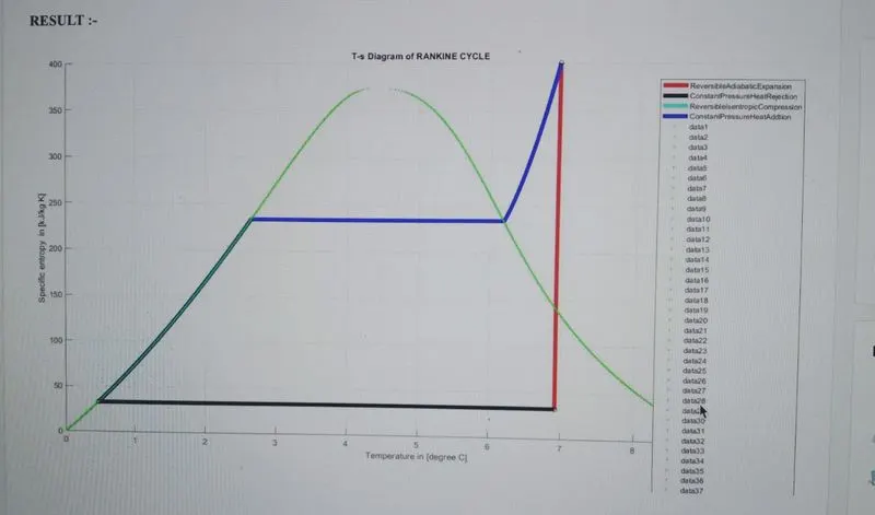
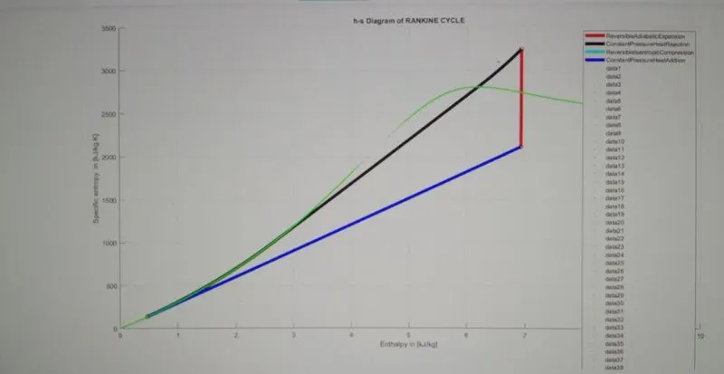
2. 1o plot the corresponding and hes plots tor the given set of inputs.
THEORY
RANKINE CYCLE THE IDEAL CYCLE FOR VAPOR POWER cYCLES
The Rankine cycle, which is the ideal cycle for vapor power plants. The ideal Rankine cycle does not involve any
internal irreversibilities and consists of the following four processes
1-2 1sentropic compression ina pump
2-3 Constant-pressure heat addition in a boiler
3-4 1sentrOpiC expansion in a turbine
4-1 Constant-pressure heat rejection in a condenser
Water enters the pump at state T as saturatod liquid and s Compressod isentropically to the operating pressure of
the boiler. The water temperature incrodsos somownat during thi tsontropic comprossion process due to a slight
decrease in the specific volume or wator. tho vortica distanco Dotwoon tdtosT and2 On tho s diagram is groatly
AGgrarod Tor clarity.
Water enters the boler as a compressed liquid at stato 2 and loaves as a superheated vapor at state 3. The boiler is
basically a large heat exchanger where the hoat originating trom combustion gases, nucear reactors, or other
sources is transferred to the water essentiaily at cornstant pressure. The boiler, together with the section where the
steam is superheated (the super-heater), Is often called the The boiler and the condenser do not invove any wok, and the purmp and the turbine are assumed to be isentropic.
Then the conservaon or onor9y rotaticOn Tor odch dovice can De expressod as Tollows:
Pump (q=0):
Wpump.in h2 - h1
pump.in
= U(P2- P)
where
h=he P, and U, =U,er
Boiler (w = 0):
m=h-h,
Turbine (q = 0):
turb,out h
Condenser (w = 0):
4out4-h
The thermal efficiency of the Rankine cycle is determined from:
net1-oul wet 4in4 out turb,out pump,in
th
INPUT PARAMETERS
peraure
Turbine Inlet Pressure s0 bas
Turbine Outlet Pressure= 0.05 bars Condcnser Inlet Pressure
A program tor s1mu tating Rankine cycle and plot required graphs.
close a
tear
5 Subscrapt for ditterent 5tate polnts
s1 = Turbine inlet or Boiler outlet, 2 = Condenser inlet or Turbine out let,
rnp 2ntet or Condenser out let, 4 = Boiler inlet or Pump out let
Tnn
ntet pr
T1= Temperature
C)
(deg
p2 Turbine outlet pressure (bar),
Descrlptlon about Tour process
A program tor s1mu tating Rankine cycle and plot required graphs.
close a
tear
5 Subscrapt for ditterent 5tate polnts
s1 = Turbine inlet or Boiler outlet, 2 = Condenser inlet or Turbine out let,
rnp 2ntet or Condenser out let, 4 = Boiler inlet or Pump out let
Tnn
ntet pr
T1= Temperature
C)
(deg
p2 Turbine outlet pressure (bar),
Descrlptlon about Tour process,
tprintr(Process (1-2) 1sentrop1c Expansion 1n the TurD1nen
tprintf(Process (2-3) 1sobaric Heat Rejection by the Condensern'
fprintf(Process (3-2)-Isentropic Compression in the Pumpn)
TprintriProcess (4-1- 1sobaric Heat Addition by the Boilern')
[9:50 AM, 7/5/2022] Ashutosh: For Inputting state variables at point 1,
p1= input('Enter the Pressure at the Turbine Inlet (in bar):');
t1 input( 'Enter the Temperature at the Turbine inlet (in Degree celsius): ');
p2input ("Enter the Pressure at the Turbine 0ut let (in bar): ');
w State variable at state point 1(1.e Turbine Inlet )
h1 XSteam("h_pT'.p1, t1); Enthalpy in (k3/kg
s1 XSteam("spT",Pp1, t1); Specific entropy in IkJ/kg K)
v1 = XSteam("vpT,p1, t1); Specific volume in In3/kg]
w State variable at state point 2(1.e Conderser Inlet)
$2 s1:
h2XSteam( 'h_px',p2,XStean('xps',p2,$2));
t2 XSteam('T_ps'p2,52);
v2XSteam( 'v_ps',p2,s2);
Specific entropy in [k3/kg K]
Enthalpy in [kJ/kg
Temperature in ldeg ree C]
Specific volume in [m3/kg
State variable at state point 3 (i.e Pump Inlet)
p3 p2;
t3 XSteam('Tsatp',p3);
h3 XSteam( "hLp',p3);
s3=XSteam( "slp'.p3)
v3XSteam( "vlp',p3)
Pressure in [barl
%Temperature in [degree C]
Enthalpy in [k3/kg]
Specific entropy in IkJ/kg K]
Intet Specific volume in [m3/kg]
W State variable at state point 4 (1.e Boiler Inlet)
s4 $3;
p4 pl;
h4-XSteam( "h_ps',p4, s4);
t4 XSteam('Tps',p4, s4);
v4 XSteam("vps',p4,54);
Specific entropy in [kJ/kg K]
%Pressure in [barl
Enthalpy in [kJ/kgl
%Temperature in ldegree C]
&Specific volume in [m3/kg)
After defining all the states now lets process each of these state and in between data variables
s Ploting Graph for Ideal Rankine cycle in "T vs "s"
figure (1)
o d on
plot ( [s1 s21, Iti t2i, coto ' e5
plot( 1S2 color,'c','linewidth", ):
plott 1s3 541,ts tl
ange spae,t Db0
a.t1.500)
nnli) XSteam('s pT'.p1, Trangeti)
h range23(i) = XSteam( 'h_ps',pl,srange(1)
h_range4ll1)= Xsteam("hps p2,5_range(1))
nd
plot (s_ range, Trange,'color", 'b', 'Linewidth ',5);
legend ( 'Revers ib leAd iabaticExpans ion", "Constant Pressu reHeat Rejection', "ReversibleIsent ropicCompres
% plot graph for ldeal Rankine cycle in "h vs s
figure (2)
ho la or
plottisi $21, Ihi h21, cotor",' inewidth,5
pLOTSrange, h_range23, 'color', "k,inewidth",5);
otottiss s41, th3 h4l,'color''c, linewidth ',5) ;
legend ('ReversibleadiahsedcC
y e a0aticExpans1on,LonstantPressureieatR…
[9:52 AM, 7/5/2022] Ashutosh: % Ploting graphs for 'h' vs 's'
figure (2)
hold on
for i 1: length (t_range)
plot (XSteam('sL_t',trange(i)),xSteam (hlt',trange(i)),'.','color', 'g')
plot (XSteam ("sV_t',turange(i)),XSteam(hV_t',trange (i)), '.','color', 'g')
end
36 Ploting Diagram for All state points for Ideal Rankine cycle in 'T' Vs 's
figure(1)
hold on
plot(s1,t1, 'ko")
plot (s2, t2, 'ko')
plot ($3, t3, 'ko")
plot (s4, t4, 'ko")
grid on
title('T-s Diagram of RANKINE CYCLE')
xlabel('Temperature in ldeg ree Cl')
ylabel('Specific entropy in [k3/kg K]')
Ploting Diagram for All state points for Ideal Rankine cycle in 'h' vs 's
figure(2)
hold on
plot(s1, h1, 'ko*)
plot(s2, h2, 'ko')
plot (s3, h3, 'ko')
plot (s4, h4, 'ko')
grid on
title( 'h-s Diagram of RANKINE CYCLE')
xlabel('Enthalpy in [k3/kg] ')
ylabel'Specific entropy in [k3/kg K]') Finally Calculating Work and Efficiency
Work transferred from the working fluid (k3/k
Work_turbine = ni h2
0_taken_out_condenser = h2 ns
Work_pump= h4-h3;
_91ven_bOl ler = hi -h4;
8ack_Work_Ratio= Work_turbine/ work_pump;
SSE 3680/ (Work_turbine - Work_pump)
Workunet= Work_turbine- Work_pump;
neat rejected trom the working fluid (k
work transrerred nto the working fluid (kJ/k
*heat transferred to the working fluid (k3/
s Back Work Ratio
Specific Steam Cons umption [kg/kwh]
Net work on the working fluid (k3/kg)
%Rankine Cycle Efficlency
Effirankine = Work_net/0_given_ boiler;
Printing Results to the USER GIVING input
Tprintr(**RANKINE CYCLE: IDEAL CYCLE FOR VAPOUR POWER CYCLE***nn ");
prantrrocess 1-2 Revers ib le adi abatic expansion process in the steam turbinen");
rprinttprocess 2-3: Constant pressure heat transfer process in the condensern '):
printrrocess -4 Revers ible adiabatic compress ion process in the pumpn");
tprintfProcess 4-1: Constant pressure heat transfer process in the bolternn
fprintf( -State variable at state point 1- )
fprintf('Turbine Inlet Temperature T1 = %.5f in Tdegree C]n', t1);
fprintf(°Turbine Inlet Pressure p1 = %.5f in tbarIn'pl):
fprintf(Turbine Inlet Entha lpy h1 = s.5t in tRJ/kgin,h1
tprinttTurbine Inlet Specific entropy s1= .5f in [k3/kg Kin',s1);
fprintfTurbine Inlet Specitic vo tume vl = S.5T in m3/Kginn,vl1)
Tprintr -State variable at state point 2- n)
fprintf('Conde rser Inlet Temperature T1 =.3f in [degree Clnt,t2);
Tprintf conderser Inlet Pressure pl = .3f in [barln',p2):
a na py n %.3t 1n Tk3/kgln', h2);
forint # ( tConderse To1at c n tKJKg KIn',s2);
Tprintt("conderser Intet specltic vo tume vi .51 1n ms/ KgIn n',V2);
fprintf("- -State variable at state point 2- n);
Tprintt Conderser intet temperature 1 31 2n 1degree CJn,t2);
TprintrConderser Intet Pressure p1 = %.3t 1n tbarjn p2)
TprintrLonderserntet tnthna tpy ni .3T 1n KJ/KgIn,h2);
fnrintf(Condorer Tota Ng InS2)
TpnntrConderser ntet specltic vo Lume vl .3t in Im3/kgInn',v2);
--State variable at state point
nlet Tempe rature T1 - s.3 in eanren clat a1,
printr
printf("Pump Inlet Pressure n1 - 3 nt5)
T Pump Inlet Enthalpy h1 .3f in fa/a1
printrPump In tet Specific entropy s1 %.3f in [k3/ka Kln:.
fprintf(" Pump Intet Specific votume vi%.3t 1n tms/Kginn,v3
3f in [k/kg Kln',s3)
m3/kalnn
Tprintr
tote var1ab le at state point 4- -n')
fprintf("Boiler Inlet Temperature Ti= .4t 1n ldegree Cln',ta)
Tprintr501ter In tet Pressure pl= .4t in barin,pa)
TprintrBo1ler In let Entha lpy hl = *.4f in tk3/kg]n', h4);
fprintfBoiler Inlet Specific entropy sl = *.4t in [kJ/kg KJn',s4)
tprintt Bo1ter ln tet specitic vo Lume vi= %.41 1n Im3/Kglnn.va
fprintf( Work and Etticlency
pnerork ransTerred Trom the wOrking tluld wturbine .4T in IR3/kgIn",Work_turbine) ;
ieat rejected from the working fluid Qcondenser %.4f in TkJ/kgln',0_taken_out_condenser);
fprintf(
Work
into the working fluid Wpump s.4f in tkJ/kg]n*, Work pump);
rprinttHeat transferred to the working T Luld Qboller *.4t in TK/ Kgin n9g1ven_bo1ler)
ransferred
fprintf( Back Work Ratio BwR = %.4f n', Back_Wo rkuRatio);
fprintf(" Specific Steam Consumption SSE .4T 1n tkg/kWh n,55E)
prntet work on the working fluid Wnet
tprintf" Rankine Cycle Etticlency ETArankine .4T nn,ETT1rankinewl100);
net
tprinttn *. SUCESSFOLLY DONE THE CALCULATLONS.
n'
6 END
clc
Printing Results to the USER GIVING input
fprintf( * tsRANKINE CYCLE: IDEAL CYCLE FOR VAPOUR POWER CYCLEt** xHnn);
fprintf( 'Process 1-2: Reversible adiabatic expansion process in the steam turbinen');
fprintf('Process 2-3: Constant pressure heat transfer process in the condensern');
fprintf("Process 3-4: Reversible adiabatic compression process in the pumpn');
fprintfC Process 4-1: Constant pressure heat transfer procesS in the boilernn');
fprintf('-
fprintf('Turbine Inlet Temperature T1 = s.5tf in [degree C]n',t1);
fprintf(' Turbine Inlet Pressure pl = s.5f in [bar]n',pl);
fprintf('Turbine Inlet Enthalpy hl s.5f in [k)/kgln', h1) ;
fprintf('Turbine Inlet Specific entropy s1 .5f in [k3/kg K]n', s1);
fprintf('Turbine Inlet Specific volume v1 = .5f in [m3/kg] nn',v1);
-State variable at state point 1-
-n');
fprintf("
fprintf( 'Conderser Inlet Tempe rature T1 s.3f in (degree C]n',t2);
fprintf('Conderser Inlet Pressure pl = S.3f in Ibar]n',p2);
fprintf('Conderser Inlet Enthalpy h1 = %.3f in [ki/kg]n',h2);
fprintf('Conderser Inlet Specific ent ropy s1= .3f in [k3/kg K]n', s2);
fprintf('Conderser Inlet Specific volume vl = %.3f in [m3/kgIn n',v2);
---State variable at state point 2--
-n');
fprintf("---
fprintf( Pump Inlet Temperature T1 = %.3f in [degree C]n',t3)
fprintf('Pump Inlet Pressure pl = %.3f in [bar]n',p3);
fprintf('Pump Inlet Enthalpy h1 %.3f in [k/kg]n', h3);
fprintf(Pump Inlet Specific entropy s1= %. 3f in [k3/kg K]n',s3);
fprintf("Pump Inlet Specific volume vi = .3f in [m3/kg] nn', v3);
--State variable at state point 3 -n');
fprintf('-
fprintf('Boiler Inlet Temperature T1 = %.4f in ldegree C]n', t4);
fprintf('Boiler Inlet Pressure pl = %.4f in [barln',p4);
fprintf( 'Boiler Inlet Enthalpy h1 = *.4f in [kJ/kg]n', h4) ;
fprintf('Boi ler Inlet Specific ent ropy s1 = .4f in [k3/kg K]n', s4)
fprintf('Boiler Inlet Specific volume v1l = %.4f in [m3/kg] n n',v4);
-State variable at state point 4--
---n');
RANKINE CYCLE1DEAL CYCLE FOR VAPOUR POWER CYCLE***
Process l-2: Reversible adiabatic expansion process in the steam turbine
Process 2-3: Constant pressure heat transter process in the condenser
Process 3-4: Reversible adiabatic compression process in the pump
Process 4-E Constant pressure heat transfer process in the boiler
-State variable at state pointl-
Turbine Iniet Temperature 11 400.00000 in [degree C
Turbine Inlet Pressure pl- 30.00000 in [barl
Turbine Inlet Enthalpy hl = 3231.57103 in |kJ/kg]
Turbine Inlet Specific entropy sl= 6.92326 in [kJ/kg K]
Turbine Inlet Specific volume vl= 0.09938 in Im3/kgl
State variable dt state pOint 2--
Conderser inlet Temperature n= 32875 in [degree cl
Conderser inlet Pressure pl= 0.050 in [barj
Conderser inlet Enthalpy hl = 21io.708 in [kJ| kg]
Conderser Inlet Specific entropy sl= 6.923 in |kJ/kg K
Conderser Inlet Specific volume vl= 22.951 in Im3/kgl
-State variable at state point 3---
Pump Inlet Temperature Tl= 32875 in [degree C
Pump Ihlet Pressurepl = 0.050 in [bar
Pump Inlet Enthalpy hl = 137.765 in [kJ/kg]
Pump Inlet Specific entropy si= 0.476 in kJ/kg K
State variable at state point 3
Pump Inlet Temperature Tl= 32.875 in [degree C]
Pump Inlet Pressure pl = 0.050 in [bar
Pump Inlet Enthalpy hl = 137.765 in [kJ/kg]
Pump Inlet Specific entropy sl= 0.476 in [kJ/kg K]
Pump Inlet Specific volume vl= 0.001 in [m3/kg
-State variable at state point 4-
Boiler inlet Temperature Tl= 32.9452 in [degree C]
Boiler Inlet Pressure pl = 30.0000 in [bar]
Boiler Iniet Enthaipy hl = 140.7622 in [kJ/kg]
Boiler Inlet Specific entropy sl 0.4763 in [kJ/kg K]
Boiler Inlet Specific volume vl = 0.0010 in [m3/kgl
-- -Work and Efficiency--
Work transferred from the working fluid Wturbine 1120.8628 in [kJ/kgl
Heat rejected from the working filuid Qcondenser = 1972.9431 in [kJ/kg]
Work transferred into the working fluid Wpump = 2.9971 in [kJ/kgl
Heat transterred to the working fluid Qboiler = 3090.8088 in [kJ/kgl
Back Work Ratio BWR = 373.9816
Specific Steam Consumption SSE = 3.2204 in [kg/kwh]
Net work on the working fluid Wnet = 117.8657 in [kJ/kg]
Rankine Cycle Efficiency ETArankine = 36.1674 %
SUCESSFULLY DONE THE CALCULATIONS
CONCLUSION
The state points of the Rankine Cycle are calculatcd by using the steam table data for water from standard
MATLAB Xstcam library
Various programs to compute property vialues of water at three regions are developed using MATLAB. Tho5e
programs are then omployed by another program which will simulate a Rankine cycle.
T-s,h-s and p-v plots of the Rankine Cycle are plotted and therefore the work and effciency of the Rankine Cycle are