Week 12:Project 2-Meshing of Rear Wheel Holder challenge
OBJECTIVE:
Follow the below-mentioned quality criteria, mesh the component given below and assign thickness:
Target Element Length = 5 Units
| S.N | Quality Criteria | Value |
| 1 | Aspect Ratio | 5 |
| 2 | Skewness | 45 |
| 3 | Warping | 15 |
| 4 | Taper | 0.5 |
| 5 | Min. Length | 2 Units |
| 6 | Max. Length | 8 Units |
| 7 | Min angle Quad | 45 |
| 8 | Max angle Quad | 135 |
| 9 | Min angle Tria | 20 |
| 10 | Max angle Tria | 120 |
| 10 | Tria % | 10 |
SOFTWARE USED: Altair-Hypermesh.
ABOUT SOFTWARE : It is a preprocessor tool which is used mainly in CAE domain.
ABSTRACT: A flat platelike holder has a threaded lug for securing a spare wheel flatwise thereagainst. This holder has lower extensions pivotally connected to brackets in turn arranged to be secured to the bumper of a pickup truck. A spring operated catch is used for maintaining the holder in a vertical position and when released allows the holder to lower to a horizontal position. The vertical supporting position of the wheel holder comprises the normal or travelling position and the horizontal position of such holder comprises a position for use as a step. The lower extensions of the holder have a bottom edge adapted to serve as a stop against the bumper mounted brackets to hold the step in a substantially horizontal position, and springs are provided between the holder and the bumper mounting brackets to resist partly the lowering rotatable movement of the wheel and its holder. A release cable secured to the spring operated catch extends into a portion of the truck for emergency release of the step if necessary, and a safety chain is connected between the vehicle and an upper portion of the step to limit the amount of downward rotation of the step when desired.
INTRODUCTION:
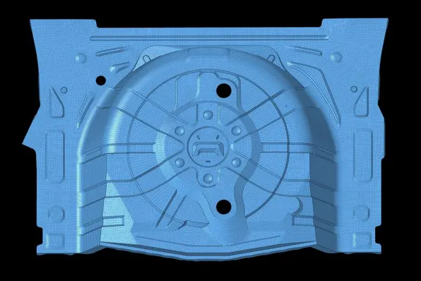
1) IMPORT A CAD MODEL
2) GEOMETRY CLEANUP
3) MID SURFACE EXTRACTION
4)SHELL/SOLID MESHING
5) ELEMENTARY QUALITY CHECK
6) MESHING IMPROVEMENT
7) APPLY LOAD AND BOUNDARY CONDITONS.
8) EXPORT IMPORTED CAD MODEL.
1) IMPORT A CAD MODEL: This is the first step in any preprocessor tool we have to import a cad model.
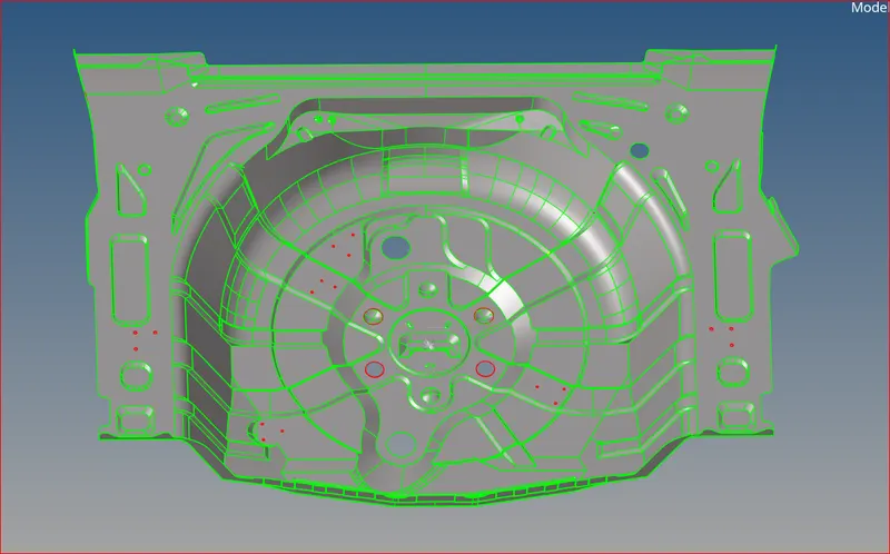
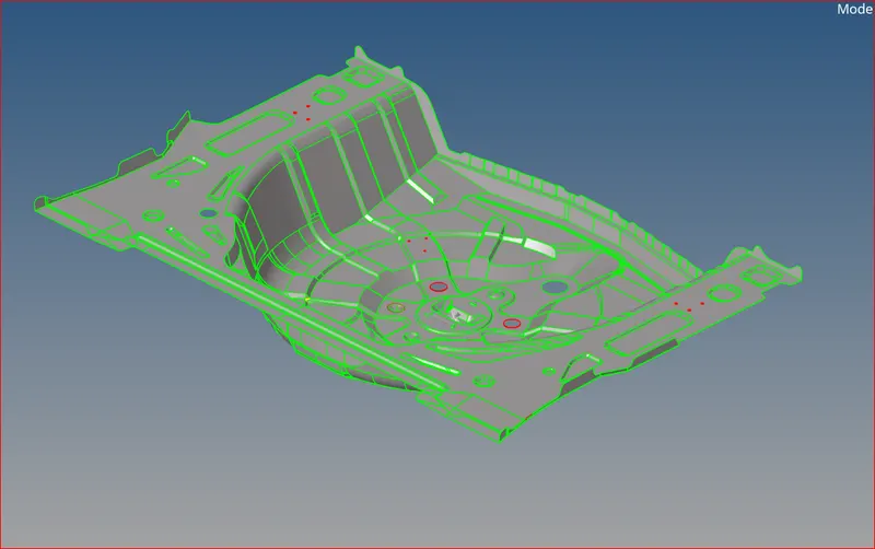
2)GEOMETRY CLEAN UP: If any unnecessary triple cons ,double cons, single cons , sharp corners, free edges etc. as a cae engineer we need to cleanup the geometry by manually using quick edit, edge edit, lines, and surfaces commands.
3) MID SURFACE GENERATION: This is the first step to take after completing the geometry cleanup.it is maily depending on component, we need to identify weather we are working with the sheet metal component ,plastic trim , etc.
- If the thickness is greater than 5mm we will choose solid meshing.
- If the thickness is less than 5mm we will go for shell meshing.
- if the thickness might be uneven then also we will choose solid meshing.
here i am taking a mod surface by using mid surace command, in that command it has some types of methods
- skin offset
- offset
- sweep+planes
- offset+plane+sweeps.
by manually checking with different components with different algorithms then only will get which method is best for which component.
generally skin offset gives the better results while taking a mid suarface, sometimes offset command.
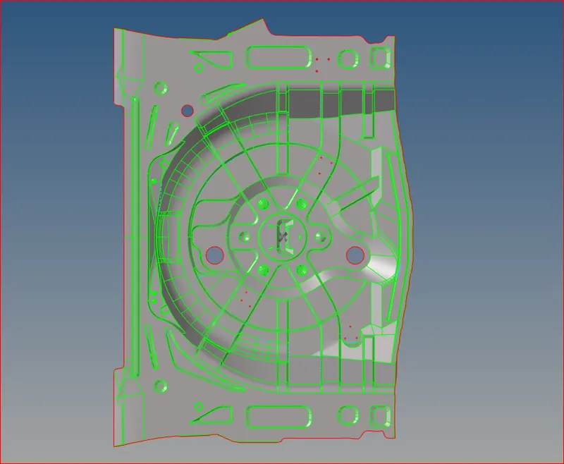
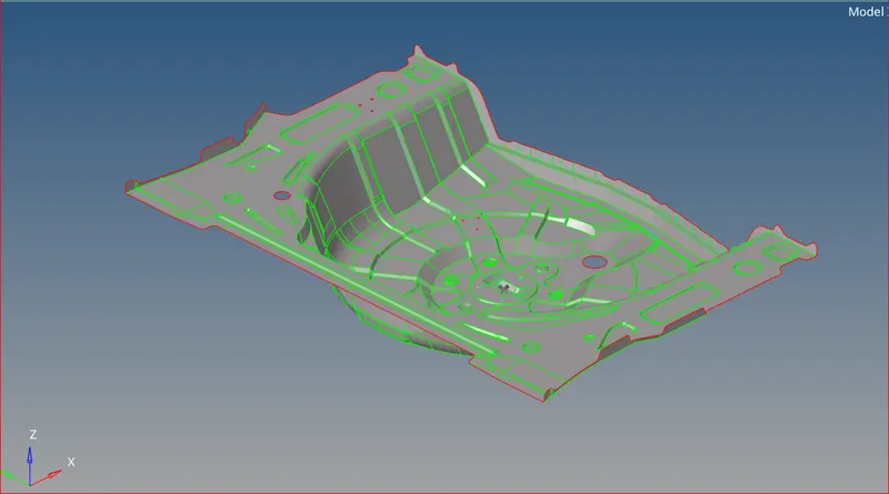
below figures represents the mid suface extraction from parent geometry.
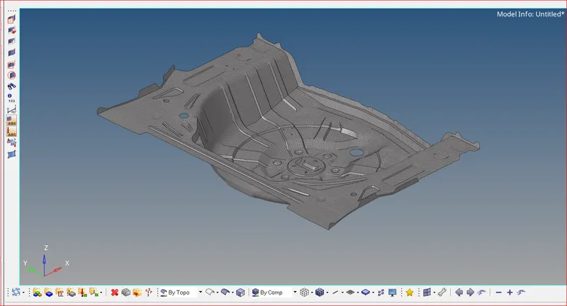
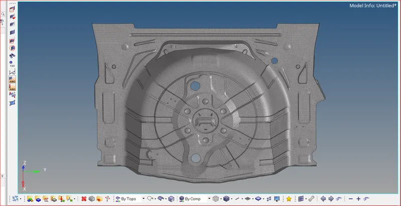
4) SHELL/SOLID MESHING: This component is sheet metal so the thickness is also same throughout the component. so i prefered shell meshing.
below figures represents the shell meshing parts.
5) ELEMENTARY QUALITY CHECK: The main use of this quality criterians it tells about how our mesh flow is.
- A good mesh flow improves result accuarcy with lesser computational time.
- A bad mesh flow provides longer simulation run time with less accuaracy.
WARP ANGLE:The angle between two local normals is called warpangle.
It is possible only if four elements available, let us take a quad element so it has four nodes then we made a cut diagonally we got two tria in the quad . so each tria element have one local normal.
SKEWNESS: an ideal tria element has an equilateral triangle and an ideal quad has a square. it is used to find the deviation from any side.
it is recommended to maintain a skewness less than 45 .
ASPECT RATIO: it is used to calculate the length of all elements .(or) it is the ratio of maximum edge length to the minimum edge length.
because of this we will get a perfect elements in quad shape.
it is recommended to maintain the aspect ratio is less than 5mm.
JACOBIAN: It is the short from for the determinant of the jacobian matrix, it does co ordination transformation.
it is used mainly we will convert critical co ordinate system to simpler co ordinate system.
it is recommended to maintain less than 1mm and greate than .6mm.
the deteminant of jacobian helps in identifying the distortion.
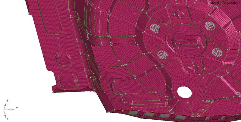
ASSIGNING THE THICKNESS: we have to assign the thickness as per the requirement and depending on the dimensions of a component.
here for all components have thcikness so i have assigned the thickness depending upon the component.
below figure represnts the thickness assigning.
RESULT: I have
- Imported a cad model
- cleaning up the geometry
- taken a mid surface
- done meshing
- assigned the quality criteria
- assigned the thickness.
- tria percentage of - 1.8%.

Learning outcomes: I learned how to
- import a cad model
- clean up the geometry
- take a mid surface
- assign the quality criteria
- make meshing
- use drag tria and element optimization options.
- made a reflect
- give a distance
- make a translate.
- take a mid surfce manuallly.
- remove the free edges using shift +f3 command.
- how to add new command in hypermesh.