Week 12- Final project
FINAL PROJECT
AIM:
To create a door interior part from the inputs of class A surface along with master section by following the design rules followed in tier 1 and OEM industries in catia v5.
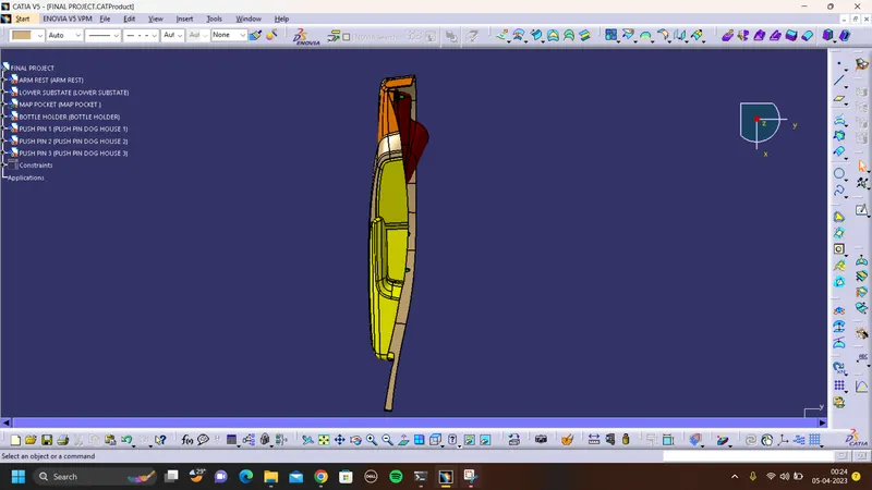
INPUTS:
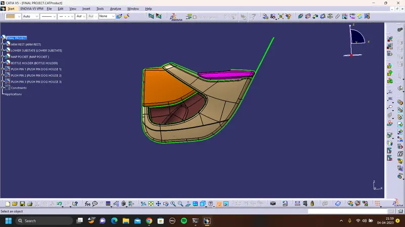
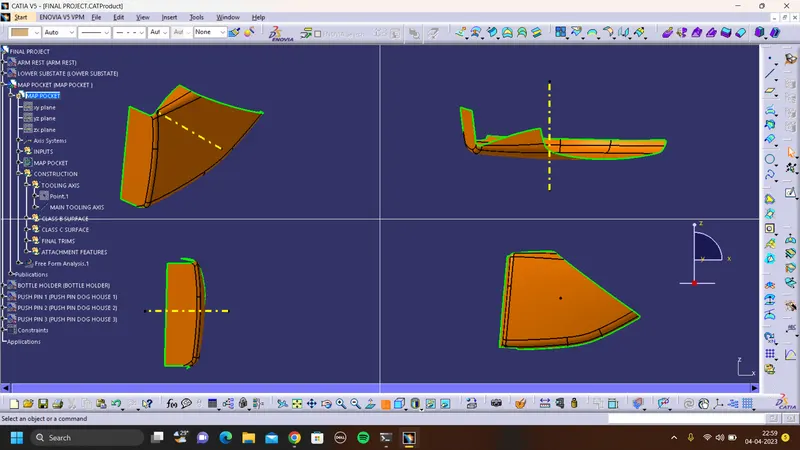
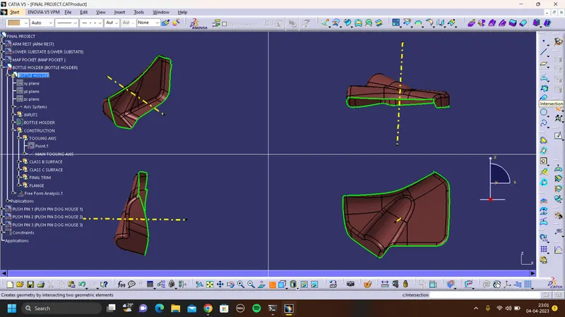
TOOLING AXIS FOR CLASS A SURFACE:
- The direction in which the mould open and closes is the tooling axis.
- Check the connectivity of the surface and ensure there will be no gap between the surfaces and then define the tooling axis.
- While creating a tooling axis give the tooling axis on a flat length surface or the surface which have a hole on it.
- Create a point on the surface where we are going to create the dummy tooling axis and using line command create an axis.
- similarly use measure inertia create a centre of point and use point and direction to create tooling axis or using bisecting method to create tooling axis.
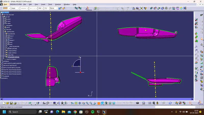
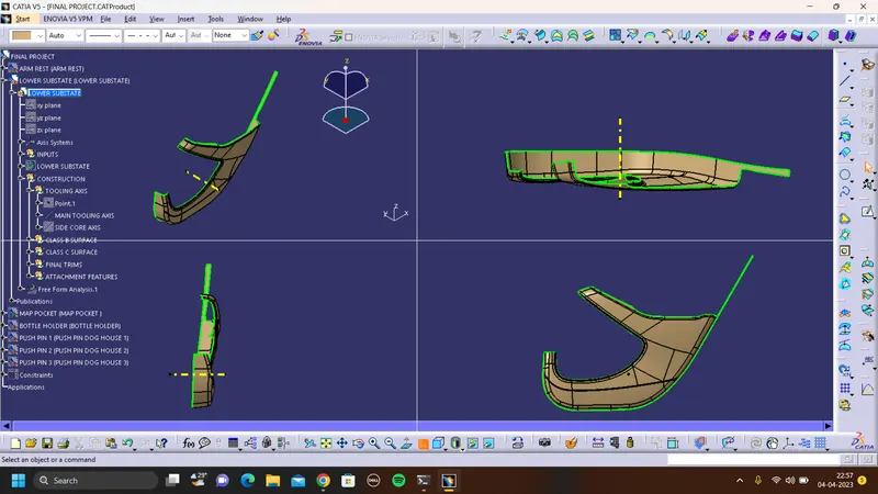
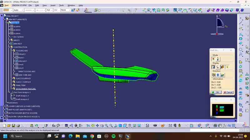
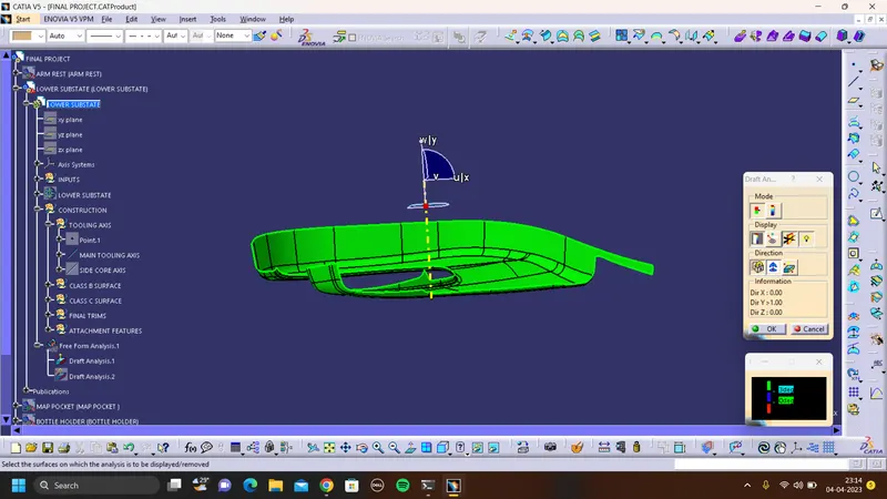
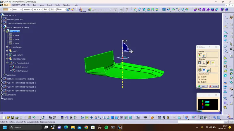
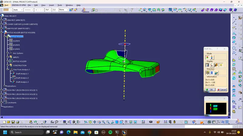
DRAFT ANALYSIS FOR CLASS A SURFACE:
ARM REST:
LOWER SUBSTATE:
MAP POCKET:
BOTTLE HOLDER:
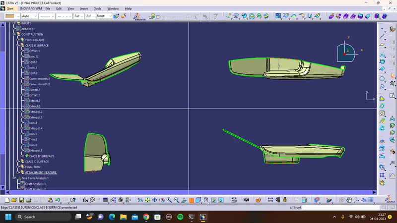
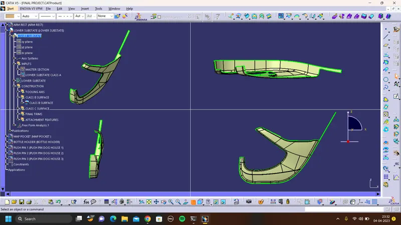
CLASS B SURFACE:
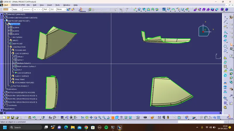
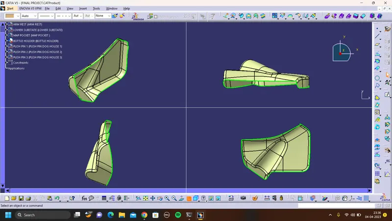
- Class B surfaces are the secondary surfaces in plastic component design.
- In this model Class B-Surface is extracted from the A-surface and it is offseted at 2.5mm in downward direction.
- work on removed patches from class A surface and create class B surface like use extract, untrim, extrapolate and trim to get surface.
ARM REST:
LOWER SUBSTATE:
MAP POCKET:
BOTTLE HOLDER:
CLASS C SURFACE:
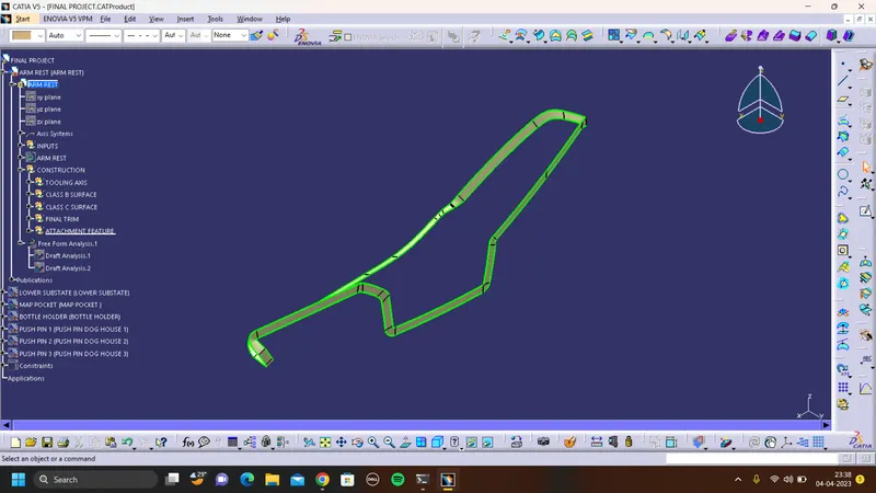
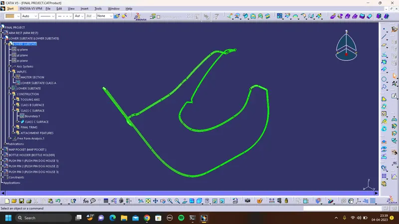
- Class C is often specified for interior surfaces not readily visible, surfaces that will be covered by another part when assembled, or surfaces which the Customer feels do not need to meet a high cosmetic finish.
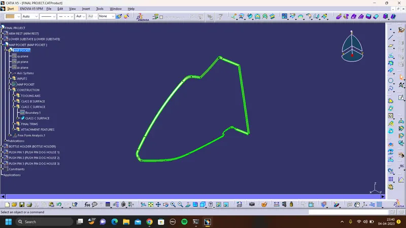
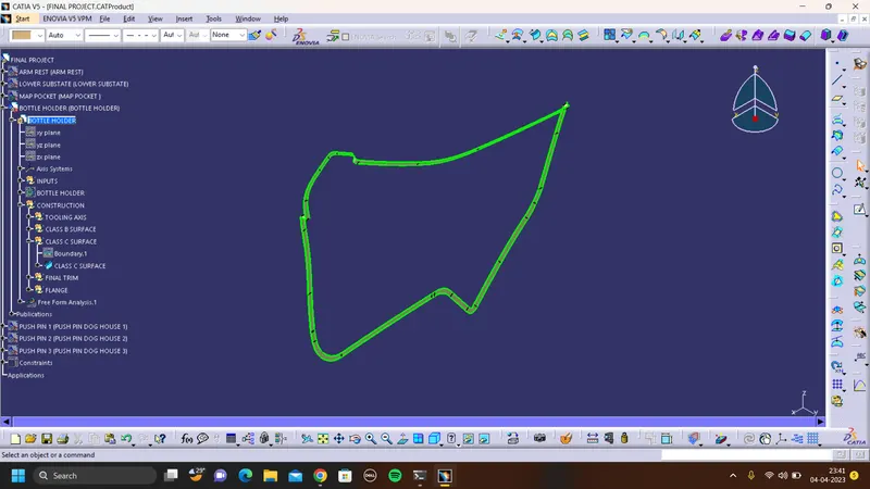
- C-Surface connects the class A-Surface and B-Surface. It is created using Sweep command.
- Boundry of the class A-Surface is swept along the tooling direction or with reference surface.
AEM REST:
LOWER SUBSTATE:
MAP POCKET:
BOTTLE HOLDER:
DOG HOUSE:
Here the dog house is required for lower substrate only. So for creating the dog house I have extracted the base surface of the lower substrate and made a point that extracted surface and sketched on it.
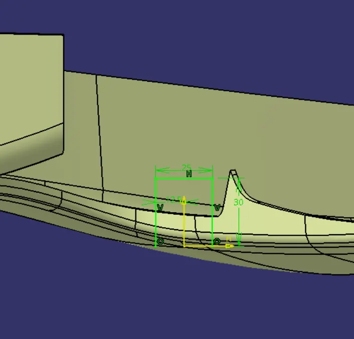
then extrude the sketch and trim to get required dog house. After closing the surface I have used the thick surface command to make a solid body giving 2mm thickness.
ASSEMBLY OF PUSH PINS:
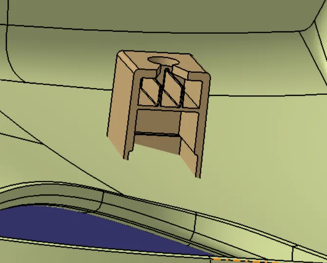
Pushpins were placed on the dog house. Total three push pins were used. Following mates are used to fixing the push pins to the dog house.
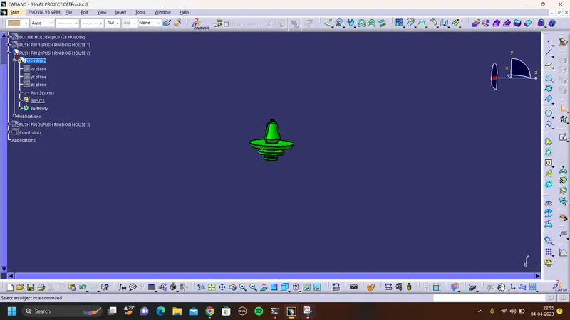
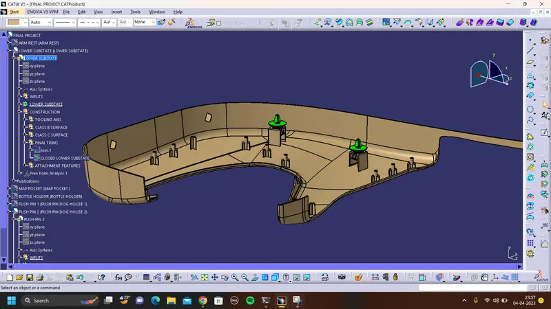
Then I have used the copy and paste special option and translated the dog house along with a push pin to different locations on the lower substrate in which I want the dog house. so basically I have created points on the lower substrate and used the point-to-point translation. After doing the translation I have just added all the dog houses to the lower substrate.
HEAT STAKES:
Heatstakes is known as thermoplastic staking is the process of joining two dissimilar metals together
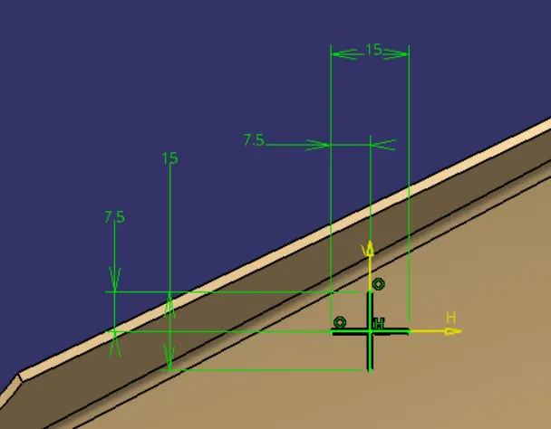
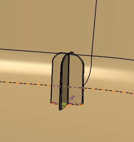
- Extract the surface that we going to create heat stake
- Use positiioned sketch and draw a heat stakes sketch
- Use pad commands for the sketch to till we required
- Draft the stakes minimum of 0.5 degree
- Add fillet 0.5mm o all faces
- Assemble the heat stake to lower subtrate solid
- Maintain a 50mm minimum between two heat stakes
- Translate the heatstakes to wherever we need
- Trim the all heat stakes with lowersubstrate solid
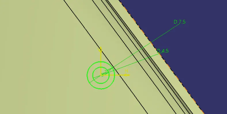
use the master section reference sketch for heat stakes and required draft ange of 0.5 provided.
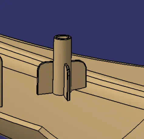
LOCATORS:
- Extract the surface that we going to create locator
- Use positiioned sketch and draw a locator sketch
- Use pad commands for the sketch to till we required
- Draft the locator for minimum of 0.5 degree
- Add fillet 0.5mm o all faces
- Assemble the locator to lower subtrate solid
- Maintain a 50mm minimum between two locator
- Translate the locator to wherever we need
- Trim the all heat stakes with lowersubstrate solid
- Maintian a height more than heat stake
FLANGE:
Create a flange for attachment of heatstakes and locators at lower substrate.

FINAL PART BODY:
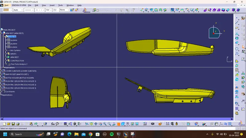
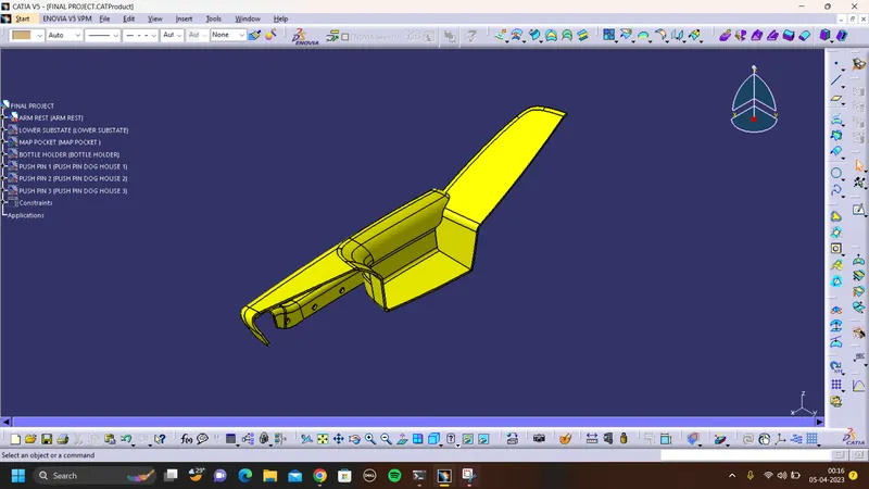
ARM REST:
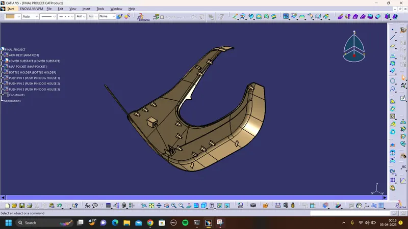
LOWER SUBSTATE:
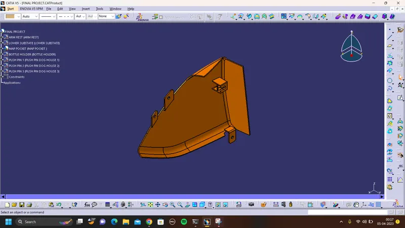
MAP POCKET:
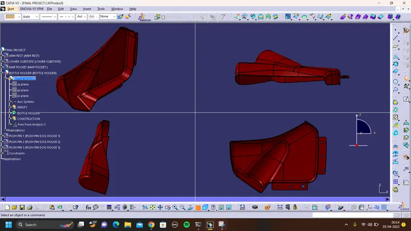
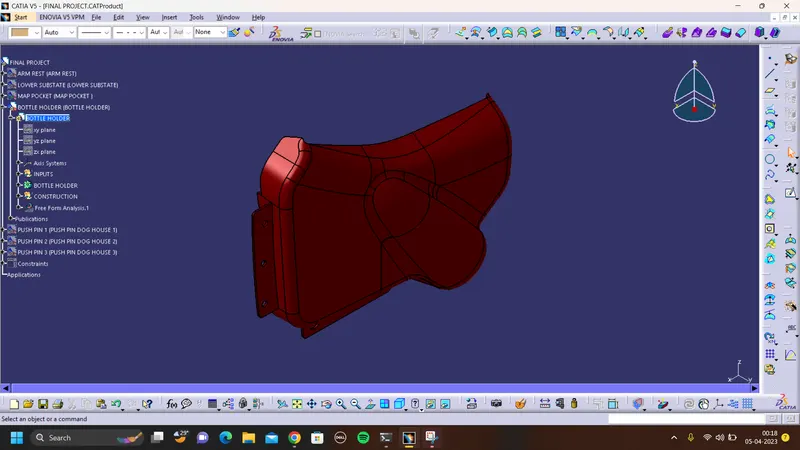
BOTTLE HOLDER:
FINAL DRAFT ANALYSIS:
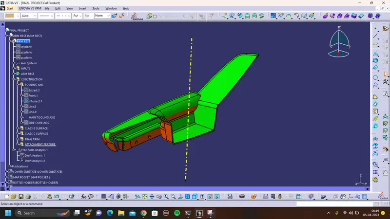
ARM REST:
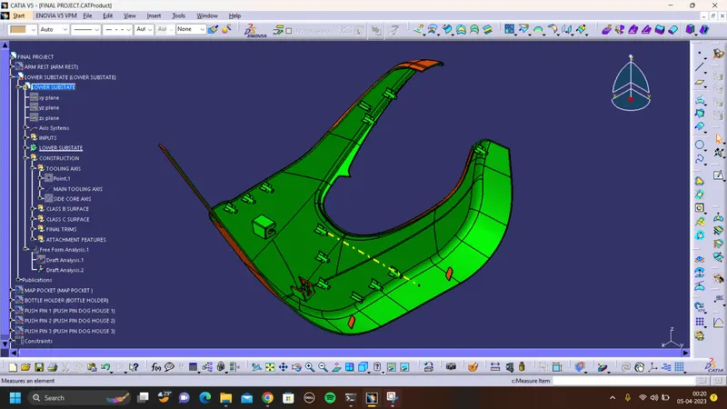
LOWER SUBSTATE:
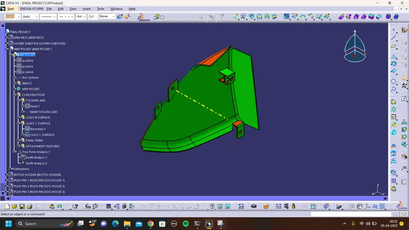
MAP POCKET:
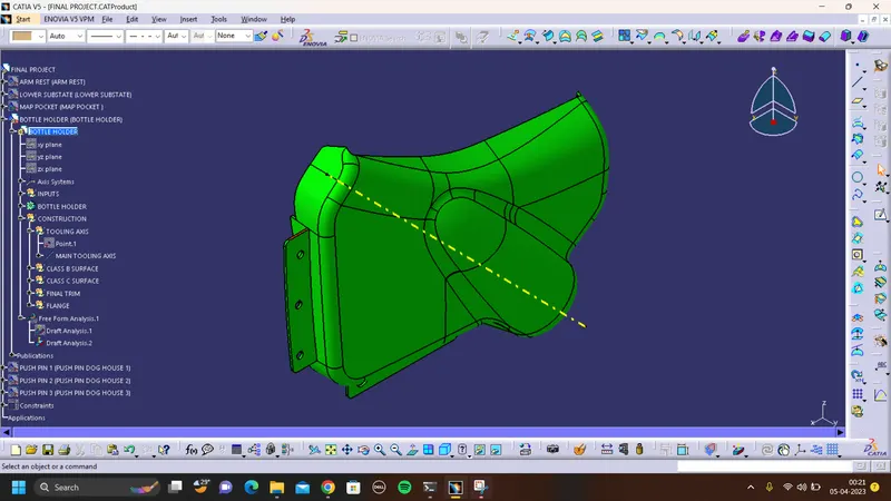
BOTTLE HOLDER:
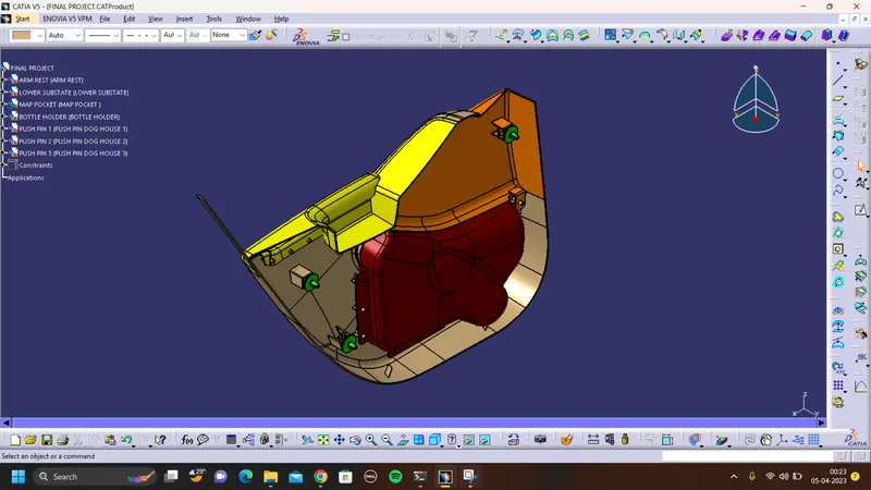
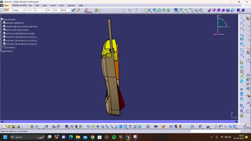
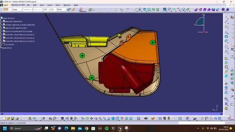
FINAL OUTPUT BODY:
ISOMETRIC VIEW:
FRONTN VIEW:
SIDE VIEW:
TOP VIEW: