Wiring harness design in CATIA V5 - 3D modeling Week 2 Challenge
Aim:
Electrically defined the given connecters and connecter clip with the help of geometry and assemble by the electrical wiring harness workbench.
Introduction:
Wiring harness:
Systematic bound of electric wires and electric parts This process is doing in CAD for assembly and production. E.g.: wire, connecters, back shell etc.
Connecters:
It is connecting electrically one function with another or connect the wires.
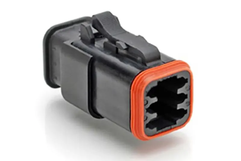
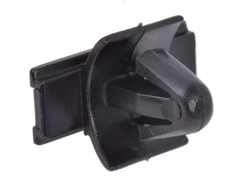
Clips:
Generally, clips are mounding some parts. In this model clips are mounding the connecters.
Tools:
For electrically define some create some geometries and electrical part design tools.
Mechanical part work bench:
Point:
It indicates one location. This tool is used to create between two points in the centre of face.
Axis system:
It is fixed on a point and give X, Y, Z direction and plane in the location which is used to define and assemble the electrical parts.
Electrical part work bench:
Define connecters:
This option is used to define the connecter with buddle entry points. After this process CATIA will take the part as connecter.
Define mounding equipment:
This option is used to define as mounding equipment. After this process it take as mounding equipment.
Define connecter connection point:
This option is used to define the connecter connection point with the help representation, contact, coincident and orientation which are given by point, surface and axis system.
Define bundle connection point:
This option is used to define the bundle entry point of connecter with the help representation, contact, coincident and orientation which are given by point, surface and axis system.
Define cavity connection point:
This option is used to define the cavity connection point of connecter with the help representation, contact, coincident and orientation which are given by point, surface and axis system.
Define cavity:
This option is used to define the cavity connection point of mounding equipment with the help representation, contact, coincident and orientation which are given by point, surface and axis system.
Electrical assembly:
Connect electrical device:
This option available in electrical assembly bench. This option is used to connect the two electrical devices. Arter defines the electrical device if we click the part it automatically assemble with help of point, axis, face of surface from electrical define.
Disconnect electrical device:
This option is used to disconnect the two electrical devices from connected devices.
Methodology:
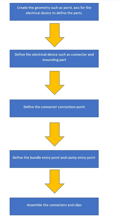
Designing:
Connecter 1:
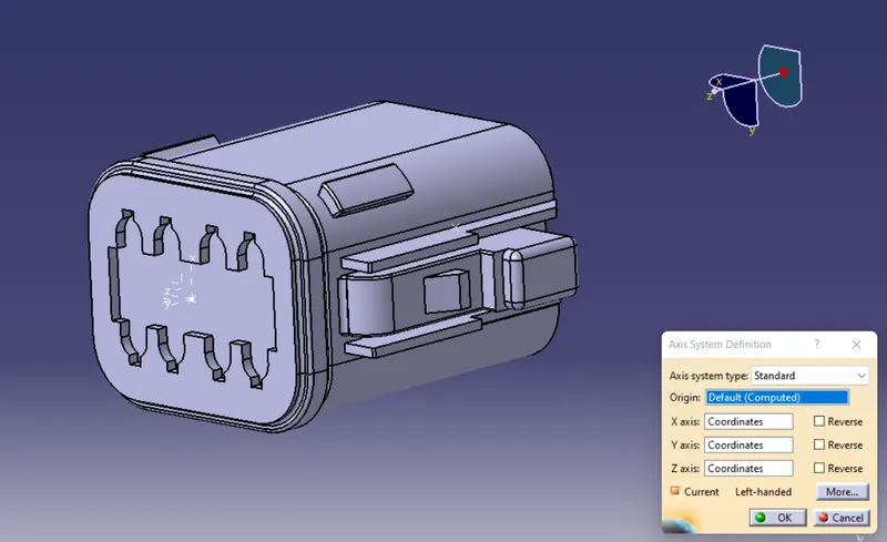
First create the geometry such as point, axis to define the electrical device.
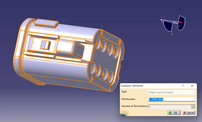
Then define the connecter with bundle entry point.

Then give connecter connection point.
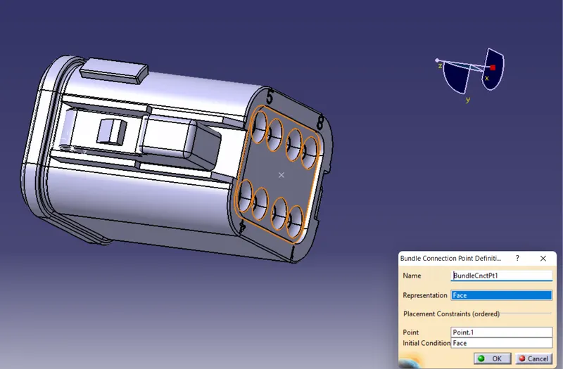
Finally, give buddle entry point and save in catalogue.
Connecter 2:
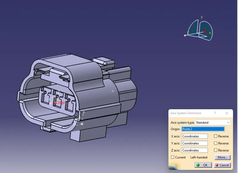
First create the geometry such as point, axis to define the electrical device.
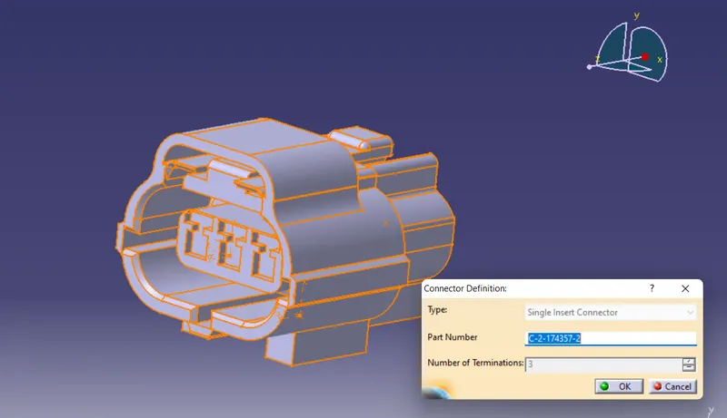
Then define the connecter with three bundle entry point.
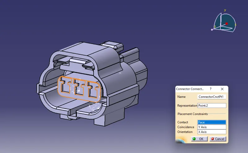
Then give connecter connection point.
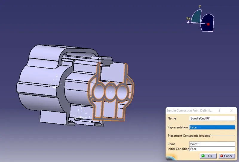
Give buddle entry point of connecter.
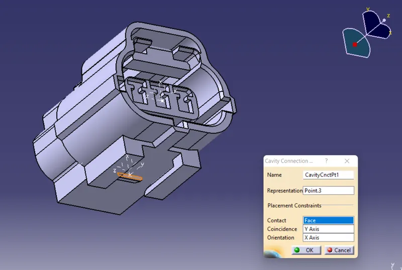
Finally, define cavity entry and save in catalogue.
Clip:
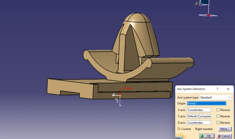
First, create the geometry such as axis, point.
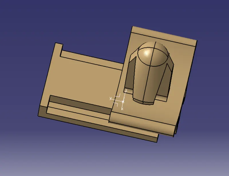
Then define a part as mounding equipment.
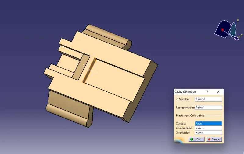
Then define the cavity with help of axis, faces and point.
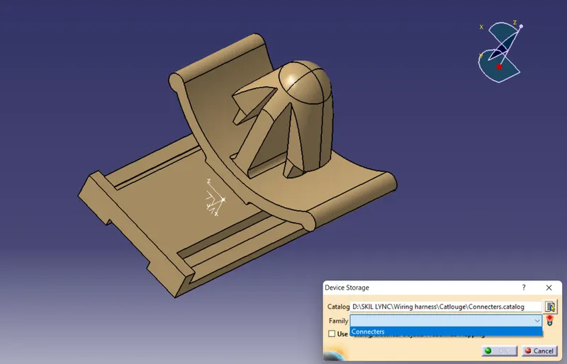
Finally, save in catalogue.
Assembly:
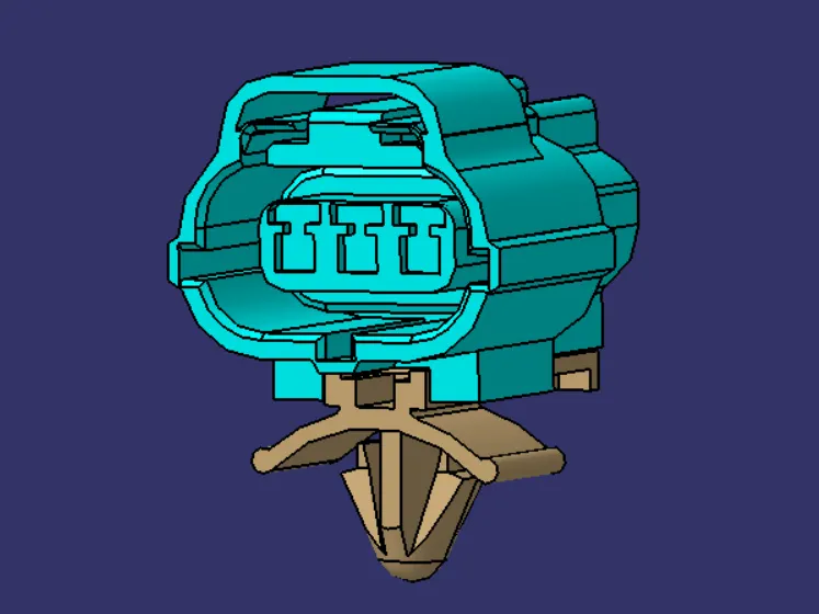
Assemble the connecter 2 and clip with help of connect electrical devices.
Conclusion:
Given connecters and clips are successfully electrically defined and assembled the connecter and clip by the help of CATIA.