Week 12- Final project
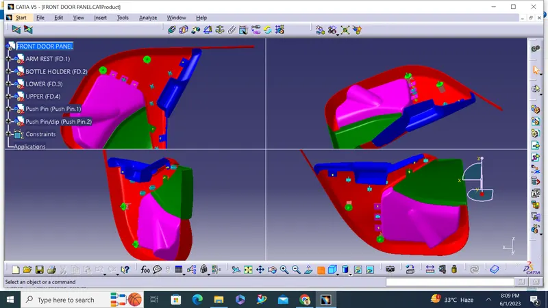
AIM: To design the car door inner panel with reference to given Class-A surface by using given mastersection, creating attachment features and performing draft analysis to check the manufacturing feasibility of the component by using software CATIA V5.
Objective: The project deals with the explanation of method followed to develop door trim inner panel. In this with the given Class-A surface, Class-B surface and Class-C surface were created along with the tooling axis. Other attachment features were also created for assembly of the different components of door trim.
Methodology:
The methodology of the project is explained here:
1. Class-A suface was extracted from the given surface.
2. Tooling Axis were created of the individual component.
3. Class-B and Class-C surface were created with the OEM guidelines.
4. Formed Solid body from the closed surface.
5. Engineering features were created for attachment.
6. Draft analyses of each component was performed to check the manufacturing feasibility.
Introduction:
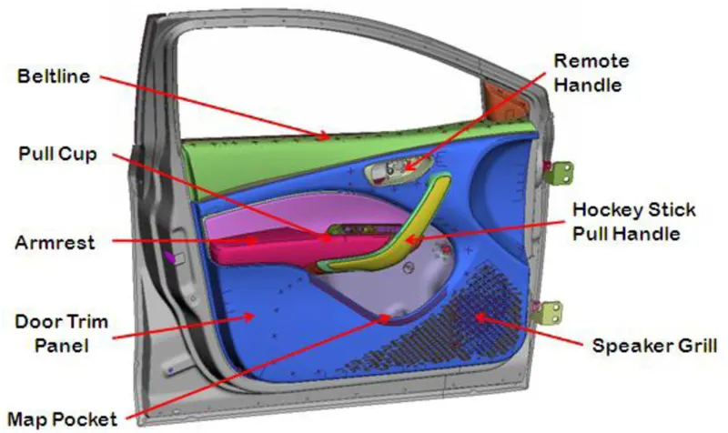
The inner door panel is an aesthetic and functional component in a car, it is the interface between the car interior and the inner working of door. Inner door panel usually consists of armrest, map pocket, bottle holder, handle bar, other switches, upper and lower substrate, storage compartments, convenience (puddle) lights and locking mechanism. Nowdays door panel is made of plastic material like polypropylene, ABS etc. which helps in making lightweight and complicated shapes of door panels.
The manufacuring Process of plastic door panel is called Injection molding. In this manufacturing process the heated molten plastic material is injected into the mould between core and cavity and cooled down to form a solid plastic component.
ARM REST
CLASS A SURFACE:
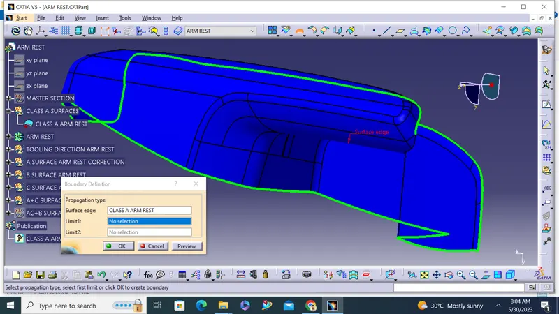
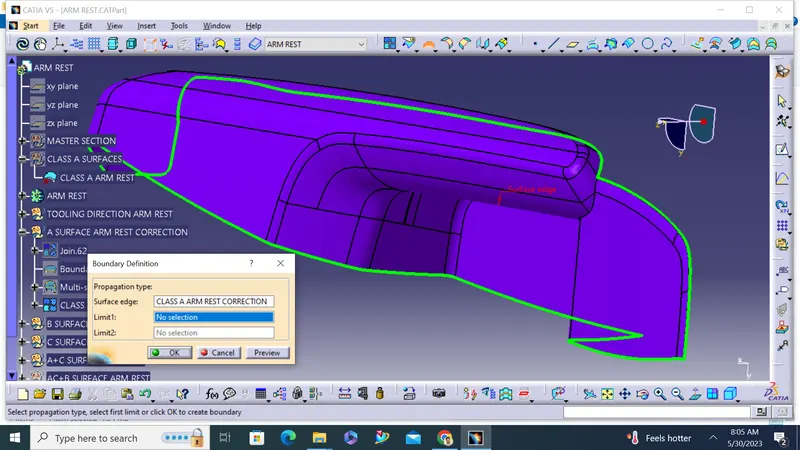
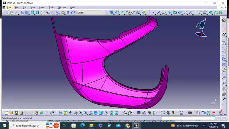
The A-surface or the styling surface is first checked for any gaps and other issues in its surfaces. This Surface acts as the input surface so any correction to be done should be with approval from the styling team or done by them. A- perfect surface is the one when a boundary is created, the lines are only on the edges of a component and its holes or cutouts as shown below.
CLASS A CORRECTION SURFACE:
MAIN TOOLING AXIS:
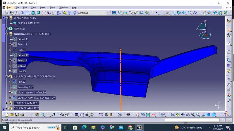
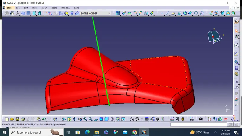
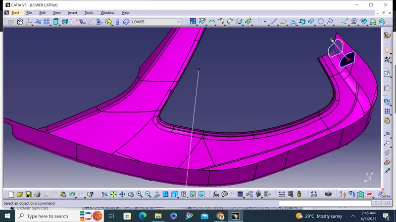
It is the direction along which the mold opens for easy ejection of the solid part.
Number of processes To Creating Tooling AXIS
- By making tooling axis along the X, Y, and Z axis
- By making the tooling axis normal to the part surface
- By using the bisection method
- Creation of the required tooling axis using the line tooland selecting the point and direction option to give extracted surface in the reference surface option and the previously created point in the reference point option and obtain the required tooling axis.
SIDE CORE TOOLING AXIS:
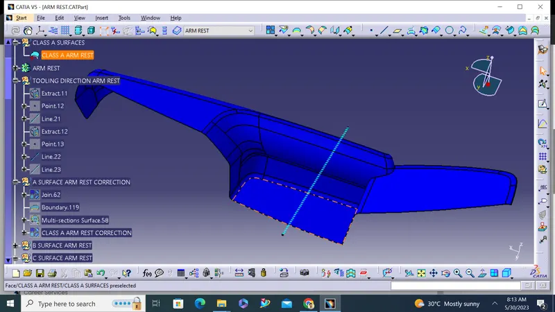
When there are through holes, recesses, and bosses, etc. on the sidewall of a plastic product which makes it impossible to release the mold, the molded product must be moved laterally. The entire mechanism that drives the lateral movement of the molded product is referred to as a slider or lifter.
DRAFT ANALYSIS OF CLASS A SURFACE:
CLASS B SURFACE:
CLASS C SURFACE:
A+C SURFACE:
AC+B SURFACE:
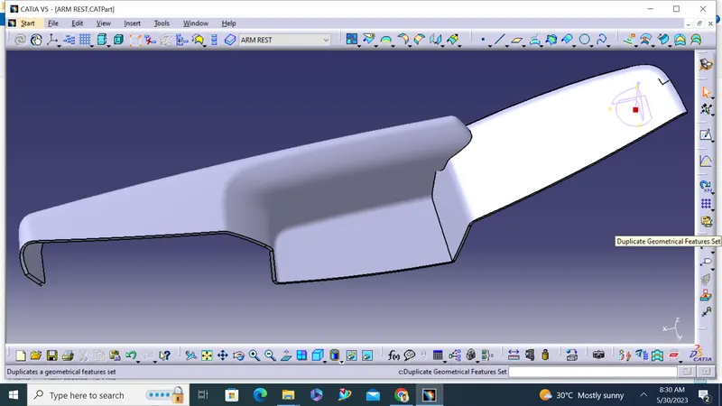
ARM REST PART MODEL:
DRAFT ANALYSIS OF ARM REST PART MODEL:
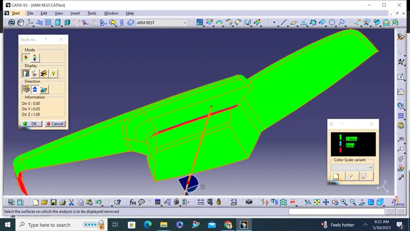
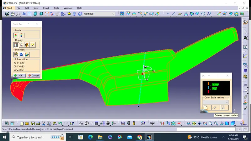
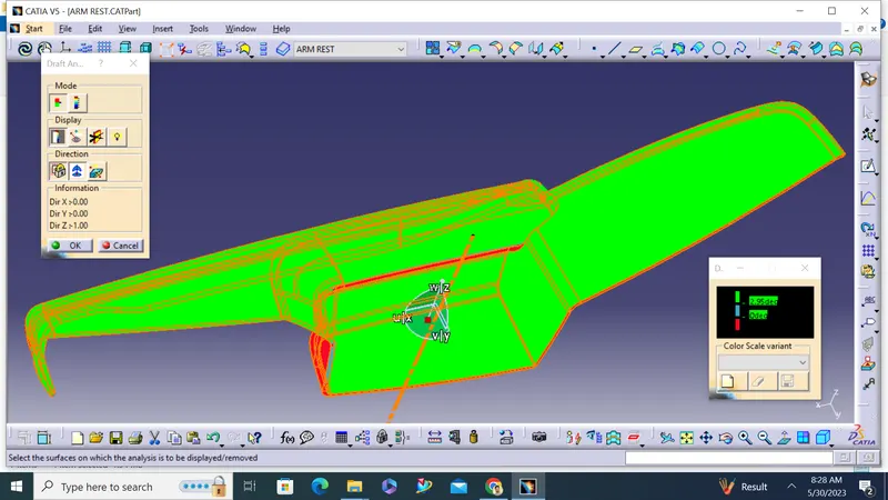
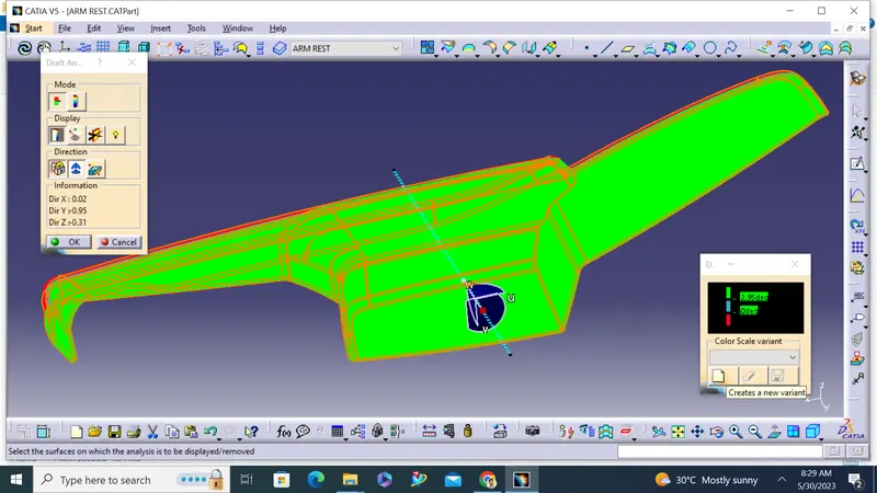
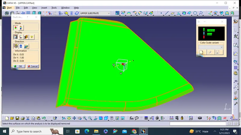
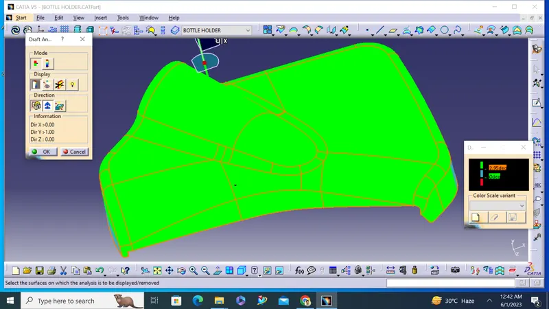
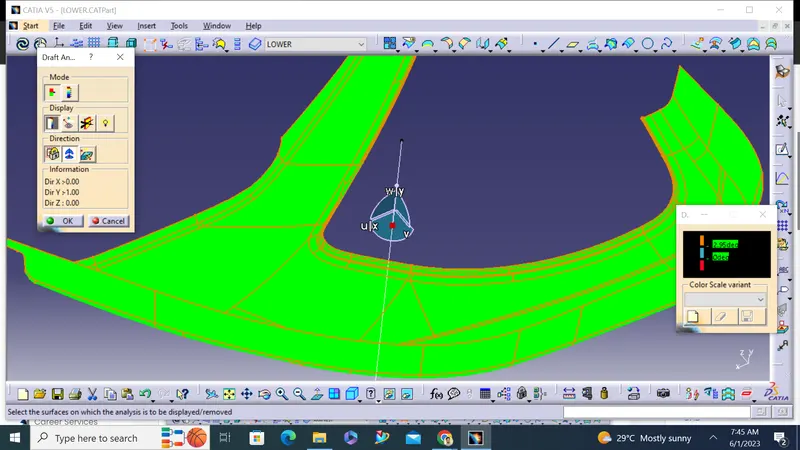
- Draft is done on the Class A surface.
- Change it to material in customise view.
- Click the Draft analysis tool and click the surface and align the compass to tooling axis.
- 3 degree is the clearing angle
- So here is photo of cleared (Green) draft.
ARMREST FLANGE CREATION
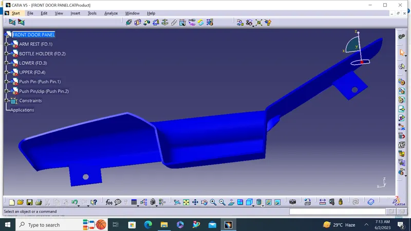
In order to Join the Armrest body with the other bodies, I created 4 Flanges separately with counter holes, Flanges are different based on the engineering features that will be held. Then these flanges are assembled to the main body (Armrest) by an un-trim feature.
Each Flange was created by extracting the surface from Class C Surface added by Generative Surface. then I applied a close surface feature to create the flange body, Drafted by 0.5 deg, Filleted. Also, it is important to mention that the counter holes were created by iso-constrained, positioned sketches and then padded it and drafted before it was removed from the main flange.
MAP POCKET
CLASS A SURFACE:
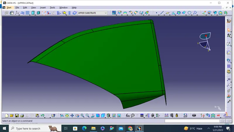
MAIN TOOLING AXIS:
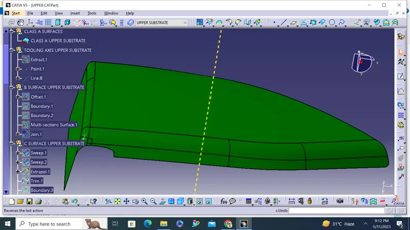
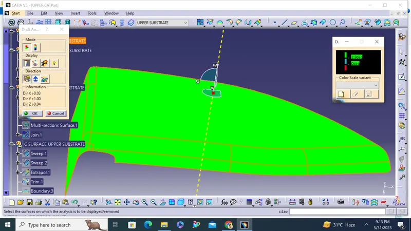
DRAFT ANALYSIS OF CLASS A SURFACE:
CLASS B SURFACE:
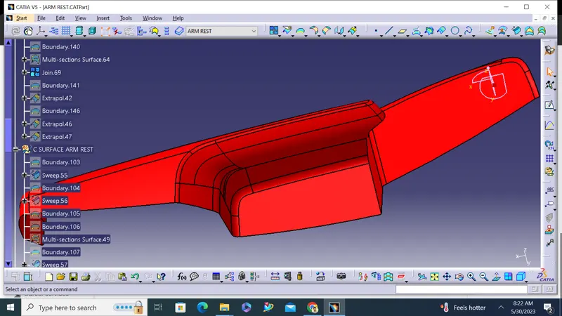
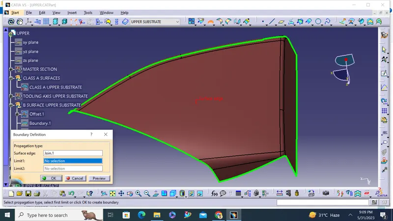
The creation of the Class B surface is a critical step in the design of the door trim panel. It involves offsetting the Class A surface by 2.5 mm as per the master section provided. However, this process can sometimes result in areas of the surface failing to offset correctly, leaving behind patches or gaps that need to be addressed. To address these issues, the surface creation features such as fill, multisection, blend, and others are utilized. These features are used to close the patches and create a continuous surface that seamlessly connects with the Class A and Class C surfaces. This process requires meticulous attention to detail, as any imperfections or irregularities in the Class B surface can impact the final product's appearance and functionality.
CLASS C SURFACE:
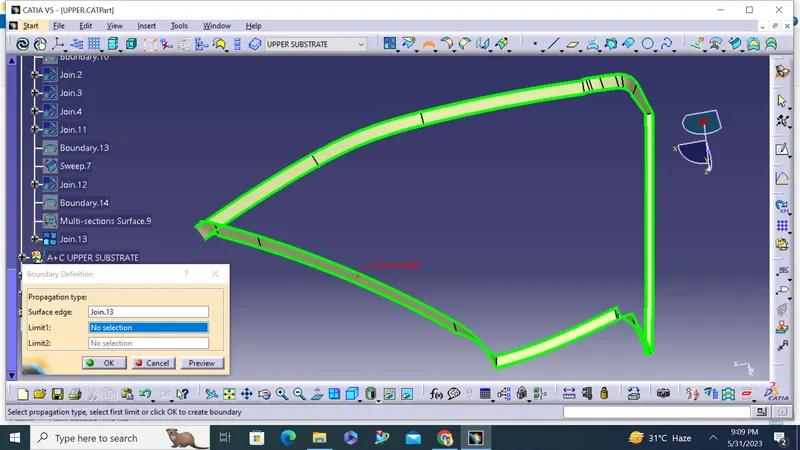
A+C SURFACE:
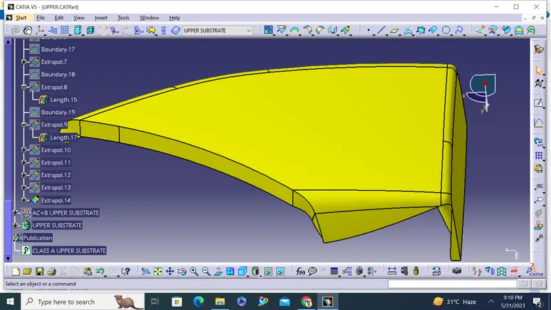
AC+B SURFACE:
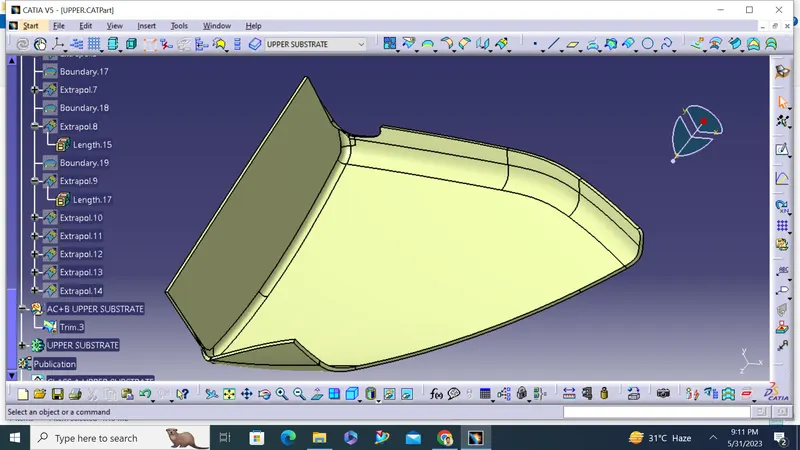
MAP POCKET PART MODEL:
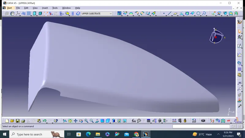
DRAFT ANALYSIS OF MAP POCKET PART MODEL:
MAP POCKET FLANGE CREATION
BOTTLE HOLDER
CLASS A SURFACE:
MAIN TOOLING AXIS:
DRAFT ANALYSIS OF CLASS A SURFACE:
CLASS B SURFACE:
CLASS C SURFACE:
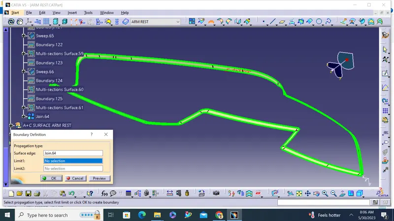
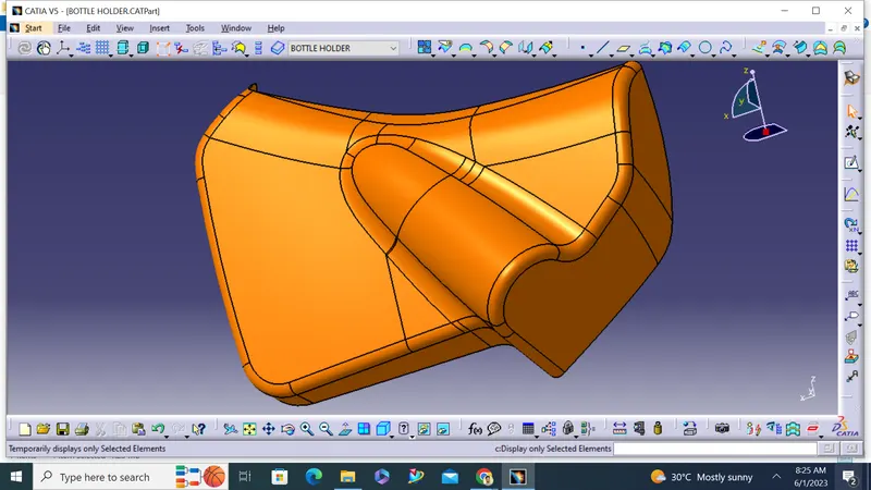
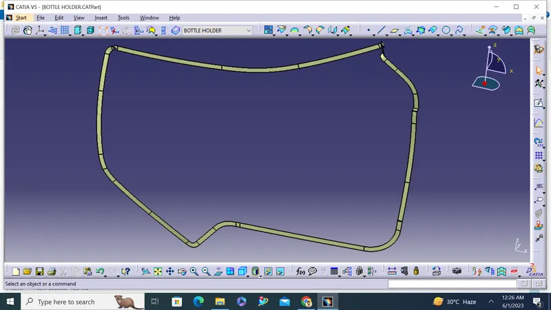
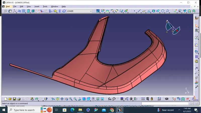
The Class C surface serves as the connecting surface between the Class A and Class B surfaces, and it is a crucial element in the design of the door trim panel. To create the Class C surface, a sweep operation is performed using the extracted boundary of the Class A surface as input. The sweep operation is carried out with a draft direction set at an angle of 3 degrees to ensure that the final Class C surface can be easily released or ejected from the mold. The result of the sweep operation is a Class C surface that seamlessly connects the Class A and Class B surfaces, creating a continuous and uniform surface that meets the required design specifications. This process requires precision and attention to detail to ensure that the final product is free from imperfections and meets the necessary quality standards.
A+C SURFACE:
AC+B SURFACE:
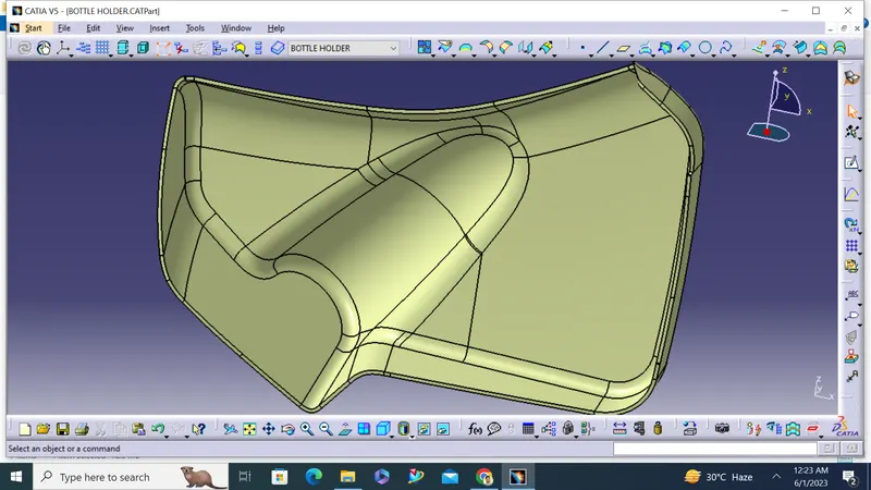
BOTTELE HOLDER PART MODEL:
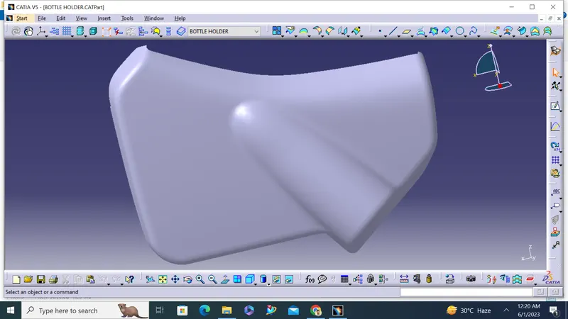
DRAFT ANALYSIS OF BOTTLE HOLDER PART MODEL:
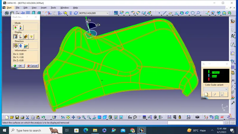
BOTTLE HOLDER FLANGE CREATION
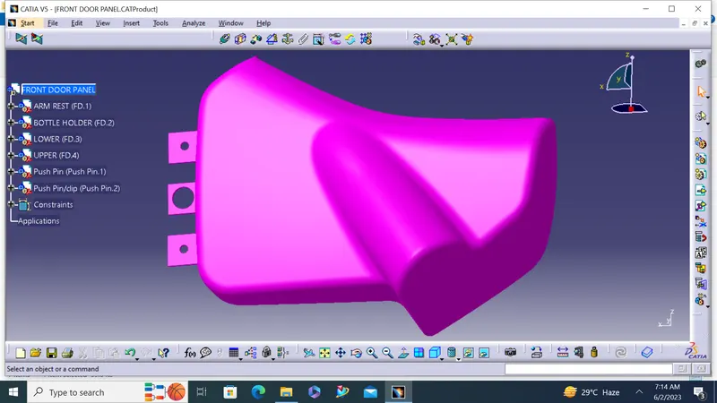
LOWER SUBSTRATE
CLASS A SURFACE:
MAIN TOOLING AXIS:
DRAFT ANALYSIS OF CLASS A SURFACE:
CLASS B SURFACE:
CLASS C SURFACE:
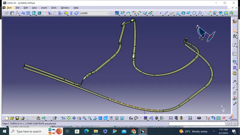
A+C SURFACE:
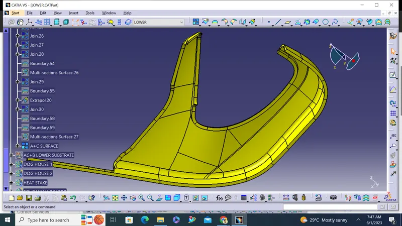
AC+B SURFACE:
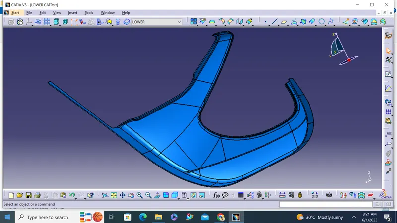
LOWER SURFACE PART MODEL:
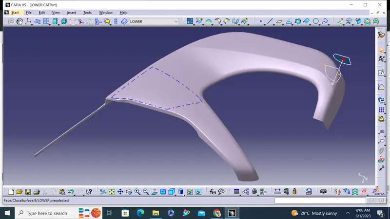
DRAFT ANALYSIS OF LOWER SUBSTRATE PART MODEL:
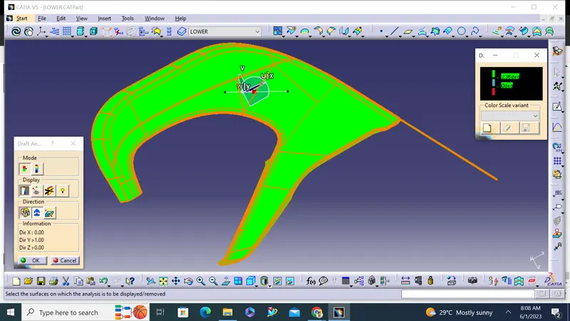
LOWER SUBSTRATE B SIDE FEATURES
DOG HOUSE:
Dog house is an engineering feature used in plastic trim design. Dog houses are used as supporting feature. Sometimes other engineering features like snaps; locators etc. are mounded on them to increase their strength. Dog houses are subjected to draft analysis to prevent breakage of the component during ejection from mould cavity. Dog house and other engineering components are built on B-surface.
DESIGN CONSIDERATION FOR PLASTICS:
1.WALL THICKNESS:
Thick sections waste material and are simply uneconomic. So solid shapes that would do the job well in wood or metal must be transformed to a 'shell' form in plastics. This is done by hollowing out or 'coring' thick parts so you are left with a component which regardless of complexity is composed essentially of relatively thin walls joined by curves, angles, corners, ribs, steps and offsets. As far as possible, all these walls should be the same thickness. Wall thickness guide range is 0.75 mm to 3mm for reinforced materials 0.5 mm to 5 mm for unreinforced materials.
WALL THICKNESS(W)=0.70*(NOMINAL THICKNESS OF PLASTIC MATERIAL)
2.CORNER RADII
Properly designed corners will make a big difference to the quality, strength and dimensional accuracy of a moulding. But there is another benefit too. Smooth curved corners help plastic flow in the mould by reducing pressure drops in the cavity and minimising flow-front break-up. Internal radii should be at least 0.5 and preferably 0.6 to 0.75 times the wall thickness.
CORNER RADII= (0.6-0.75) * (NOMINAL THICKNESS OF PLASTIC MATERIAL)
3.DRAFT ANGLE:
Tooling must be cleared for easy ejection of the component, from the core cavity. In order to clear tooling certain value of draft is given to the component. Minimum of 2-3deg is provides on all plastic components.
DRAFT ANGLE=2-3 DEGREE
4.FILLETS:
Fillet on the inner side = 0.25 * Thickness of the plastic material
Fillet on the outer side = 1.25 * Thickness of the plastic material
Fillet on the coring edges = 0.25 * Thickness of the plastic material
Coring thickness = 0.40 * Thickness of the plastic material
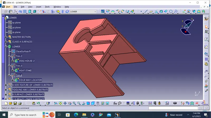
DOG HOUSE SIDE CORE TOOLING AXIS:
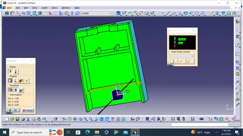
This is the axis used for the draft analysis while clearing the inner surface of the dog house. Providing 0.5 degrees to the inner surface will achieve the desired degrees for the proper ejection of the core and cavity without distorting the inner surface.
While arranging the Dog house always tries to keep the gap between the front face in the direction of the lifter axis is 90mm for the easy removal of the core while traveling in the direction of the lifter axis
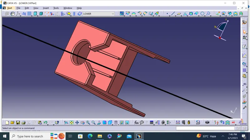
DRAFT ANALYSIS OF DOG HOUSE:
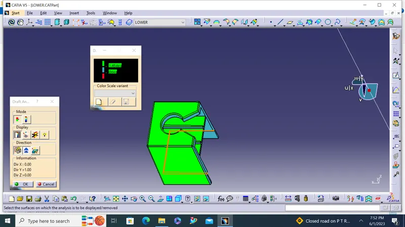
PUSH PIN:
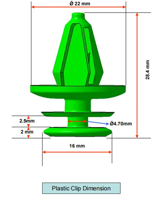
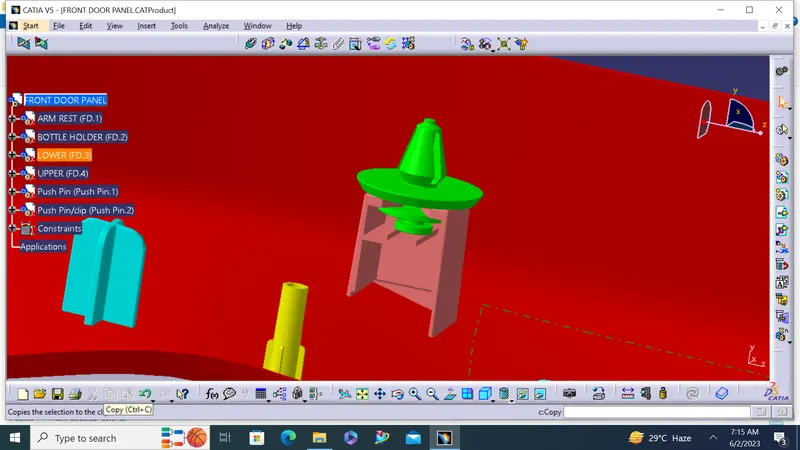
Push pins are a popular mechanical attachment because they provide flexibility and dependability at a low cost. Flexible design. Hole location and attachment forces can be customized for each specific application.
HEAT STAKE:
In manufacturing products with thermoplastic components, it is often necessary to join a thermoplastic to apart of dissimilar material, whether it be a metal, dissimilar plastic or other material. This technical information sheet provides design guidelines, configurations and techniques for successful heat staking.
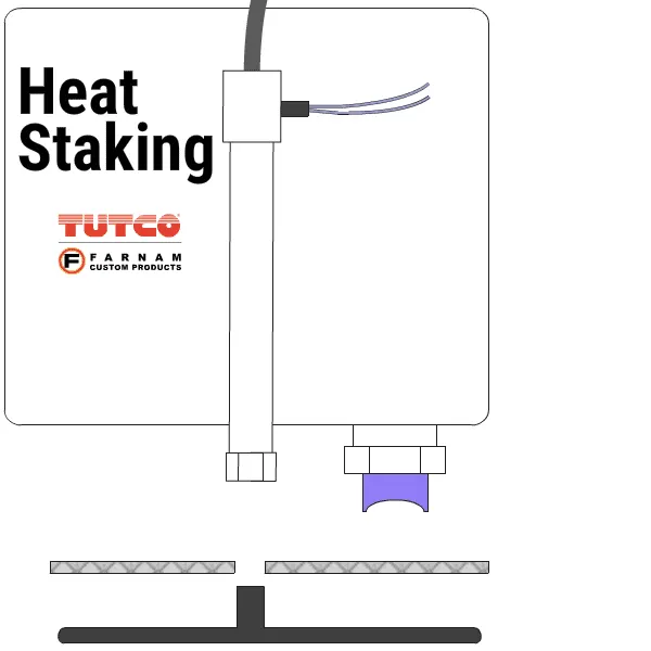
Thermal Staking or Heat staking is an assembly method that uses the controlled melting and reforming of plastic stud or boss to capture or lock another plastic or metal component of an assembly in place. The plastic stud protrudes through a hole in the component to be locked in place. The heated thermal tip contacts the top of stud, which melts and fills the volume of the tip cavity to produce a head, locking the component in place. The progressive melting of plastic under continuous pressure forms the head. When staking, the right combination of heat and pressure for the application is critical.
Heat staking also known as thermoplastic staking is the process of joining two dissimilar materials together. In heat staking we use local heating and cooling to raise the temperature of plastic components and allow plastic reforming to be carried out. This reforming can be used in a wide variety of applications.
Applications range from staking plastic boss’s for assembly of car door panels to joining PCB’s to plastic housings.
Advantages
- Simplification of machinery
- Reduced cost of machinery
- No vibration damage
- No particulates
- The ability to stake metalized coated applications
- The capability to stake in difficult to access or restricted areas.
- Multiple fastening points
- Allow higher density of welds compared to hot air cold form or ultrasonic welding.
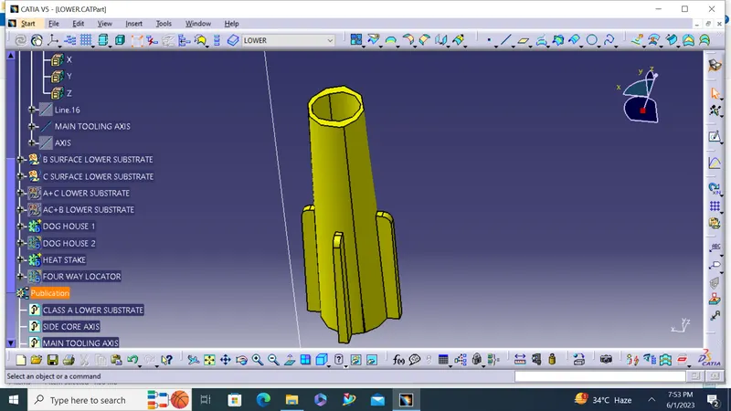
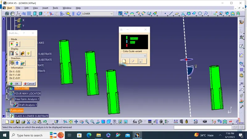
DRAFT ANALYSIS OF HEAT STAKE:
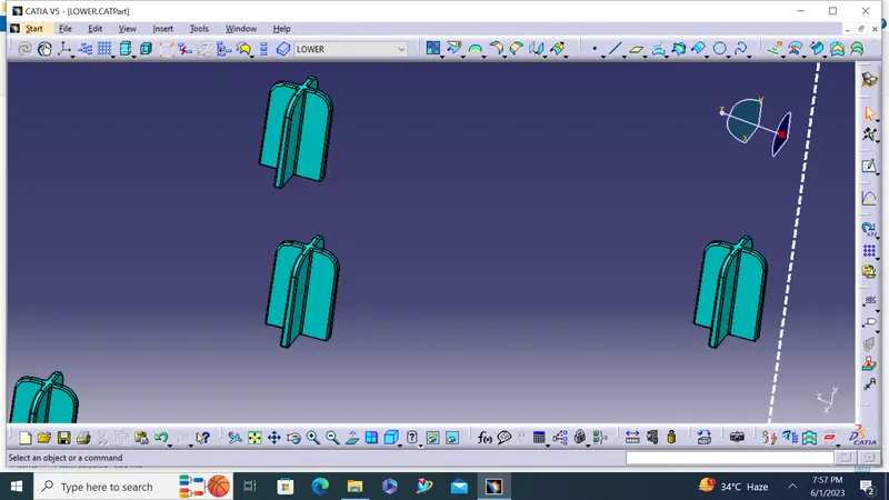
FOUR WAY LOCATOR:
- Locators are used to locating the position of the mating part while assembling.
- The design rule for the locator is mostly the same as the rib but the height of the locator should be more than the heat stakes at a min of 5mm.
- The locator also constrains the movement of the mating part.
- The gap between Flange and the locator should range between 0.5mm and 1 mm.
- There are two types of locators.
1. 2-Way Locator.
2. 4-Way Locator.
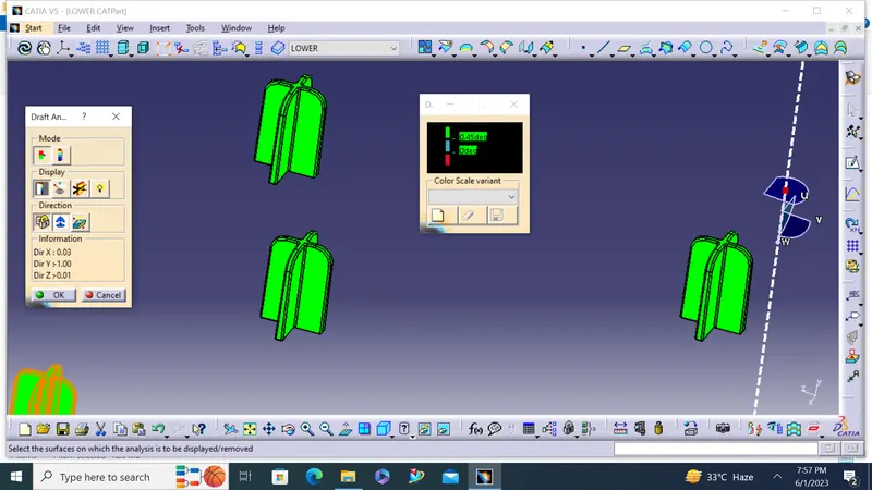
DRAFT ANALYSIS OF FOUR WAY LOCATOR:
FINAL PROJECT
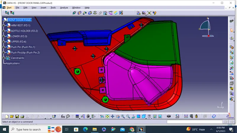
FINAL PROJECT VIEWS