Fender Design Challenge
Explanation of Fender and manufacturing process:
The fender is the curved part of the car’s body that sits on top of the wheels and holds them in place. It is not only a safety component but also enhances the overall look of your vehicle. Its primary function is to shield and protect the passenger compartments by preventing sand, mud, rocks, liquids, and other roads spray from being thrown into the air by the rotating tire.
Types of Fenders :
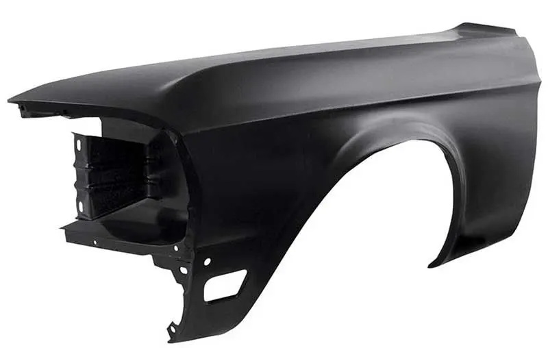
1.Full Bumper Type :
This type of bumper is not commonly used because this design is more scrap producing one during manufacturing. The blank of steel or aluminum usedto produce this type has more wastages. This type is not economically good to manufacture.
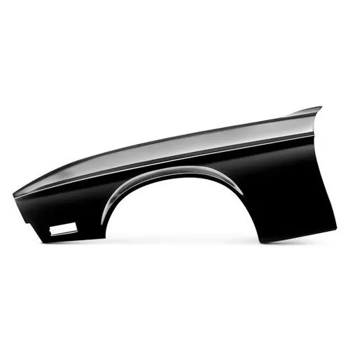
2.Half Bumper type :
This types of fenders most commonly used. The con's of full bumper type is satisfied in this design, and the blank area of wastage while producing the part is drastically reduced by scrap management.
Manufacturing process of automobile fender, comprises the following steps:
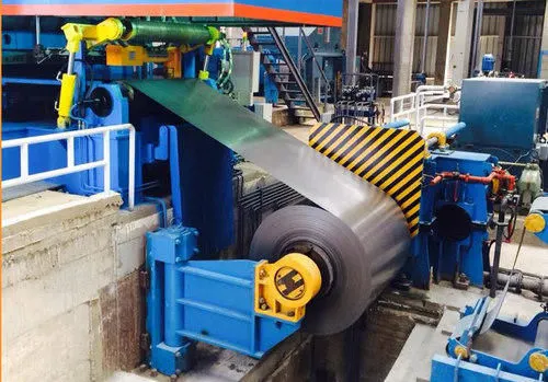
The first step: open straight snips plate: first select applicable cold coiling specification, cold coiling is opened flat; Then according to production material specification, will open cold coiling after flat and be cut into the iron plate of corresponding size; Finally, the iron plate after shear is cleaned to iron filings;
Second step: oil pressure, punch press: first iron plate is extended; Secondly to its trimming and punching; Then to its flanging and shaping; Finally, after shaping completes, then carry out one-off hole-piercing; Completed the making of lappet plate body;
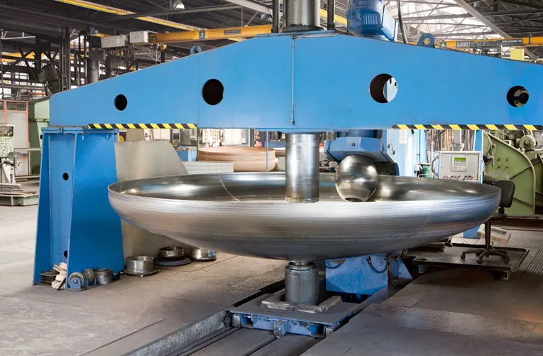
The 3rd step: First iron plate is stamped out to required outline blank (blanking); Then to completing the further molding of iron plate of outline blank; Finally, it is carried out to punching;
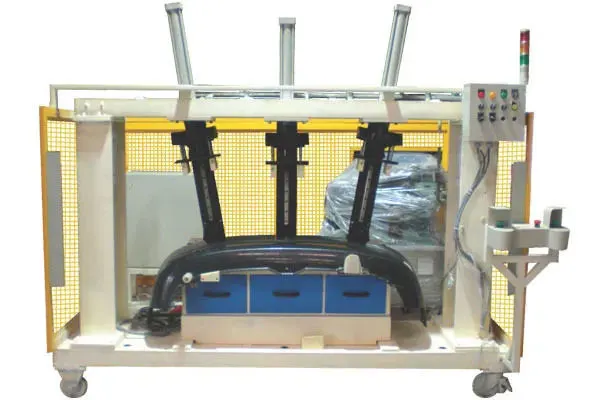
The 4th step: panel beating assembly welding: Carried out to spot welding; Then point is welded on lappet; Finally lappet body and carried out to sanding thorn and ending.
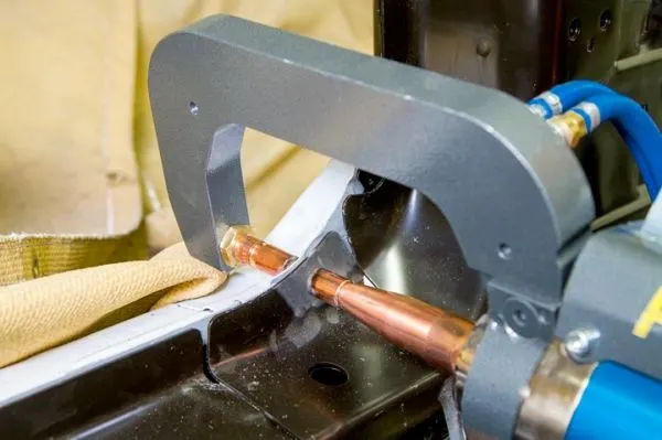
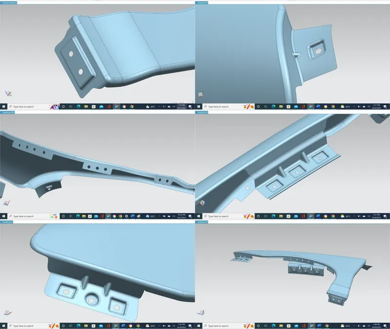
Design of front fender from the given skin data and the master section provided with Drip mounting, A-pillar, Sill, Bumper and Baffle (splash) Mounts:
150MM from head light starting to starting point of drip area.
At end of drip area to A pillar mounting starting point 150MM-300MM.
Here we start with A pillar:
Off set curve in face about 5MM inward to fender:
- Curve on surface here is spline no any continuity or intersection
- Trim sheet for A pillar mounting
- Using law extension command with face option on A pillar surface
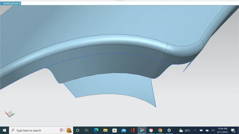
Here we creating drip area:
- Again Off set curve in face about 0 MM inward to fender
- Creating datum plane on curve to measure distance 150MM from head light starting point to drip area starting point
- Intersection line made in plane
- Another datum plane generated from law of extension at the A pillar region to drip area about 150MM and intersection line made in plane
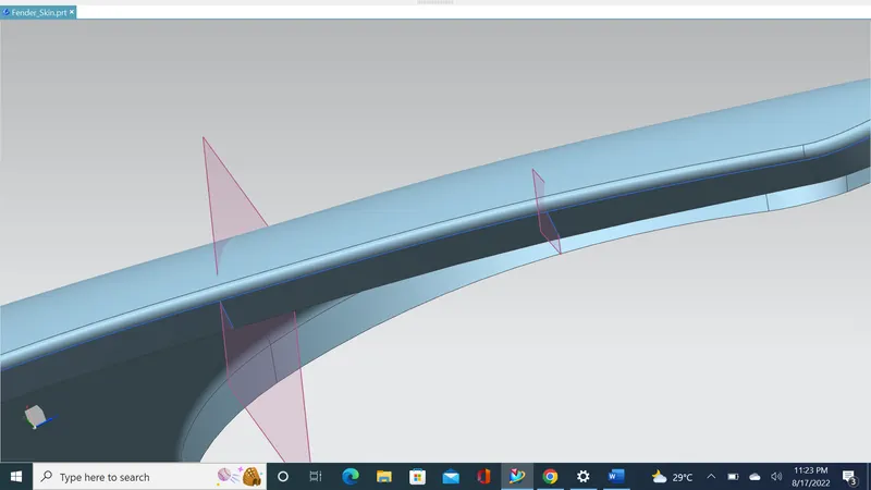
- Hide plane go to the curve on surface command and then trim the sheet
- Decide bumper region also
- Yet again generate curve on surface
- Then trim sheet will get drip area
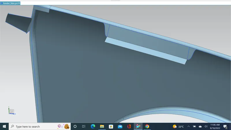
- Law of extension 8MM with 40 degree angle
- Law extension down ward about 16MM with 5 degree (Perpendicular 90 degree for 5 degree we will give 85 degree)
- Distance from edge of fender flange to 16mm extension should be less than 40MM (we got 38.10MM)
- According to Pythagoras Theorem
- 4.24 MM upward with 45 degree angle
- 1.5 MM with 0 degree angle
- 2 MM with 15 degree angle
- From 2 MM extension to 25 MM edge extension should be 5MM
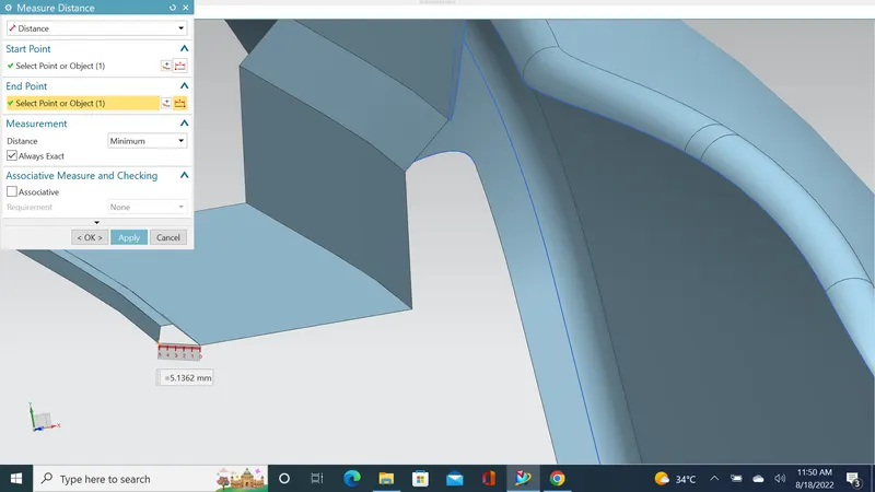
- Face blend 6MM, 3MM, 3MM, 3MM & 3 face blend
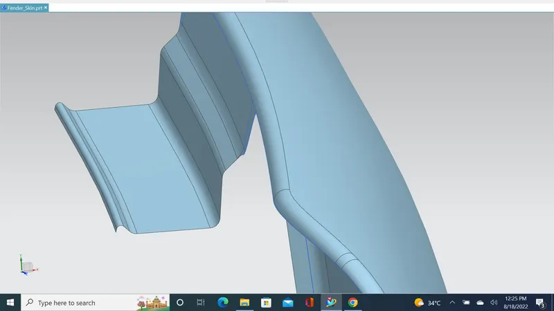
- Applying face blend between A pillar mounting and fender edge
Mounting creating on flat surface:
- Sketch the rectangle on 25MM extension surface
- Use project curve option project sketch rectangles on the surface
- For a flat emboss at bottom produce datum plane using curve and points under three point option with off set zero
- Apply Emboss operation on those rectangle and ensure there is no minimum radius of curvature at the bottom of emboss
- Generate face blends in those rectangular emboss region
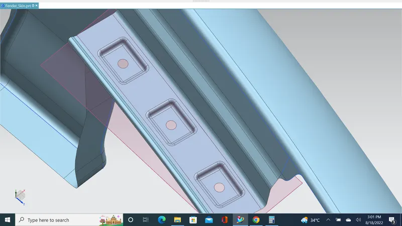
Trimming unwanted area:
-
Creating bumper area & sill mounting area
- Providing relief section in corner edges to flow stress concentration avoid damage or chipping
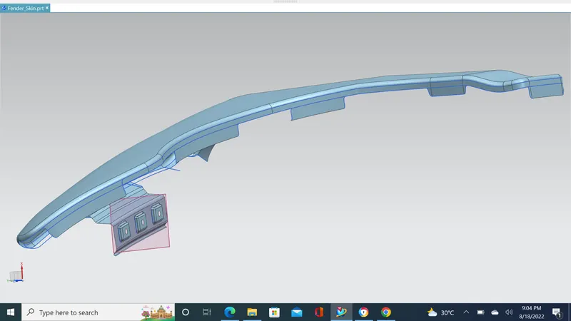
Working Sill region:
- Extending sheet in sill area as much as require
- Creating datum plane on extend area
- sketch on plane rectangle and circle
- Ensure the sketch fully constrain
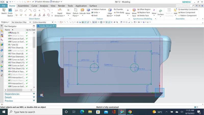
- Apply Emboss operation on those rectangle and ensure there is no minimum radius of curvature at the bottom of emboss
- Generate face blends in those rectangular emboss region
- Trim the circle in 5MM radius
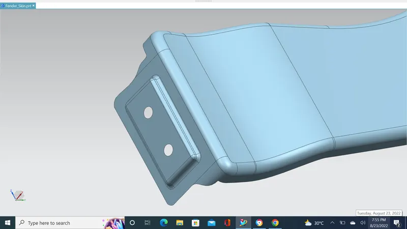
Working on bumper mounting area:
- Extending sheet in sill area as much as require
- Creating datum plane on extend area
- sketch on plane rectangle and circle
- Ensure the sketch fully constrain
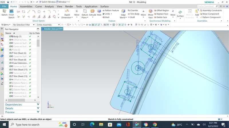
- Apply Emboss operation on those rectangle and ensure there is no minimum radius of curvature at the bottom of emboss
- Generate face blends in those rectangular emboss region
- Trim the circle in 5MM radius
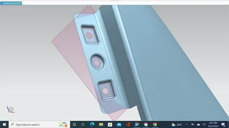
Working on A pillar area:
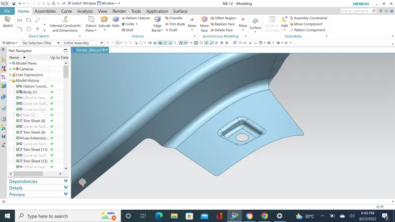
- Creating datum plane on extend area
- sketch on plane rectangle and circle
- Ensure the sketch fully constrain
- Apply Emboss operation on those rectangle and ensure there is no minimum radius of curvature at the bottom of emboss
- Generate face blends in those rectangular emboss region
- Trim the circle in 5MM radius
Baffle (splash) Mounting area:
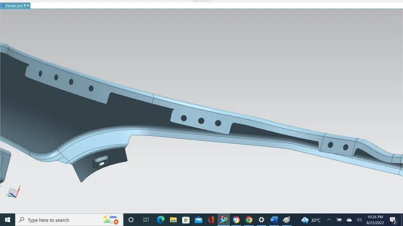
- Creating holes for baffles
- Trim sheet feature is used to create holes of 5mm
Conclusion:
Developed the Drip, Bumper, Sill, A pillar and Baffle mounting areas by following design skin data with help of NX.
Note: Those area provided with dart to increase extra strength locally.