Week 11 - Louver/Grille characterization
Aim: To characterize grill of electronic enclosure for different Reynolds number.
Grills are an important feature of any electronics enclosure be it natural convection cooling or forced convection. While designing the enclosure for electronics cooling, thermal engineer is always concerned about tradoff between thermal performance and fan power. As grills impacts the fan power, it becomes necessary to characterize grills so that one can design fan and select best appropriate location for it.
Steps to carry out simulation to characterize the grill.
Step-1: Open project file in Icepak.
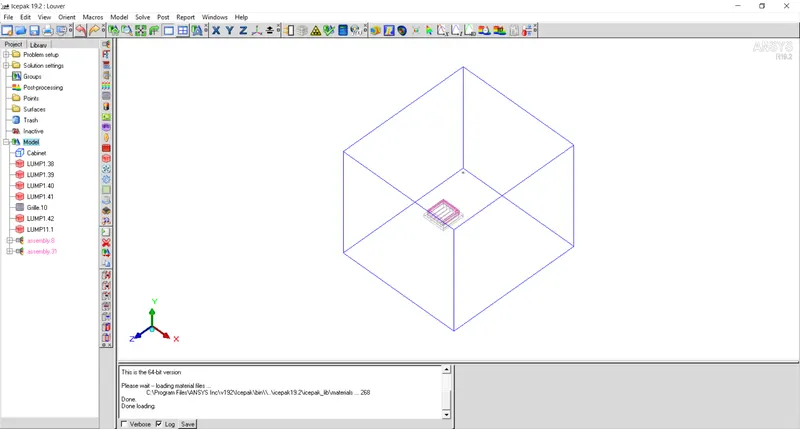
Step-2: Create a new assembly containing all the parts inside the cabinet.
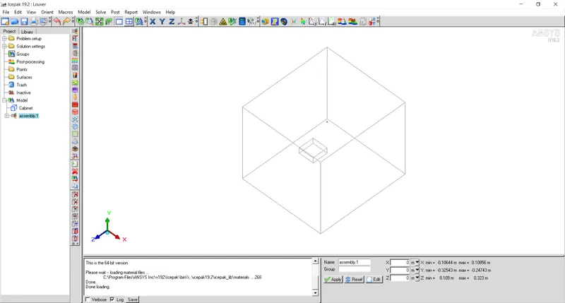
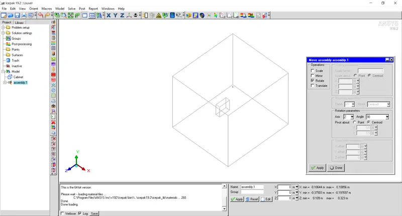
Step-3: Rotate the assembly by 90 degrees about Z axis and resize the cabinet in Y and Z directions.
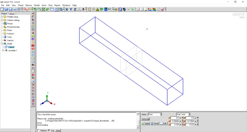
Make sure that minX and maxX are openings and other are walls.
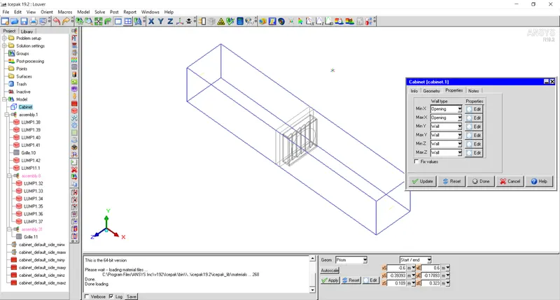
Step-4: Assign velocity at inlet of channel in terms of Reynolds number.
In this case, air flows from minX to maxX.
To create a parametric study, we have to create an expression for velocity in terms of Reynolds number.
Let's say, density of air, `rho_a = 1.204 frac{kg}{m^3}`
dynamic viscosity, `mu_a = 1.825times10^-5 frac{kg}{m-s}`
Hydraulic diameter for channel is, `D_h = 4*A_c/P`
where, `A_c` and `P` are cross section and perimeter of channel respectively.
`A_c = 0.214 times 0.215 m^2`
`P = 2 (0.215 + 0.214)`
Hence, `D_h = 0.2145 m`
Now, Reynolds number, `Re = frac{rho_a*V_a*D_h}{mu_a}`
where, `V_a` is mean velocity of air in channel
From above equation, velocity can be represented in the form of Reynolds number as below:
`V_a = frac{Re*mu_a}{rho_a*D_h}`
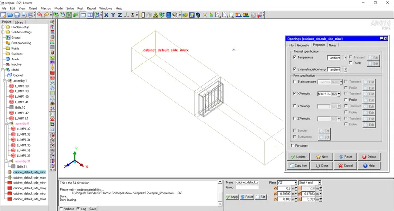
= `Re* 7.067 times 10^-5 m/s`
here, Reynolds number varies from 100 to 600 with an increment of 100.
Insert above expression for minX face of cabinet.
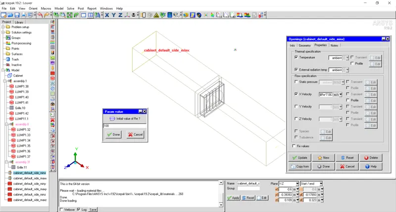
Also, enter 100 as initial value of Reynolds number.
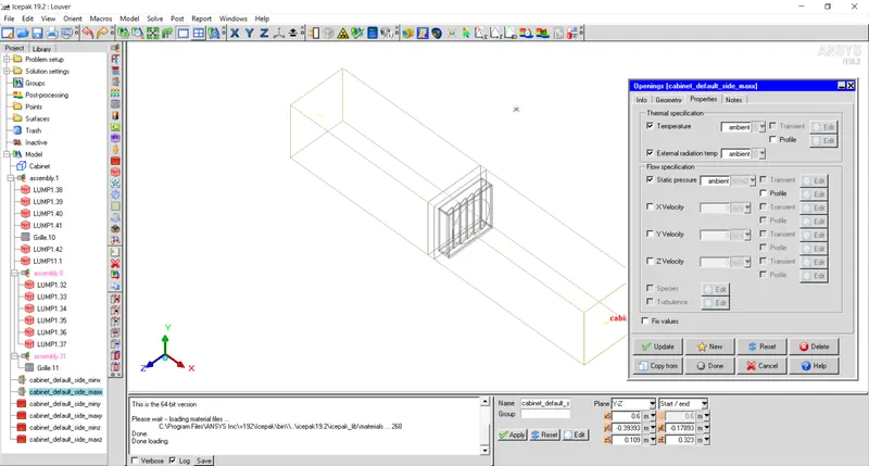
Step-5: For maxX face, apply ambient pressure as static pressure.
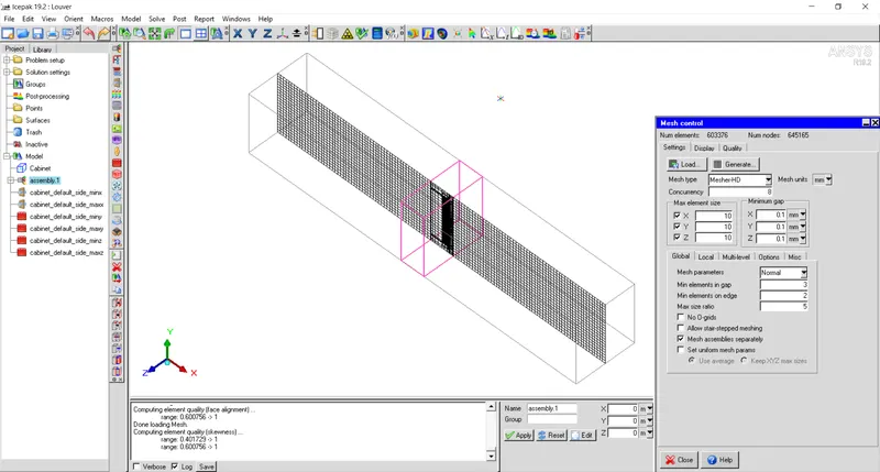
Step-6: Generate mesh with global parameters shown in figure below.
Non-conformal mesh is generated as shown below.
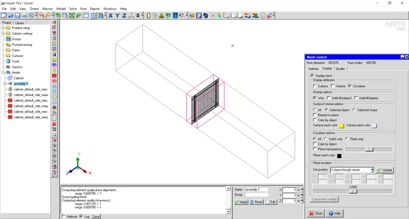
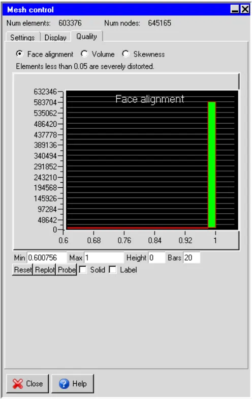
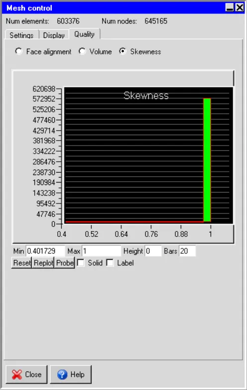
Mesh quality is also checked and it is seen that mesh generated is of good quality.
Face alignment:
Skewness:
Step-7: Define parametric study.
Now, to start study, first one needs to create parametric variables and assign values to variables.
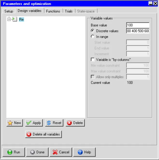
In this simulation, Reynolds number is parametric variable that varies from 100 to 600.
First select parametric trials.
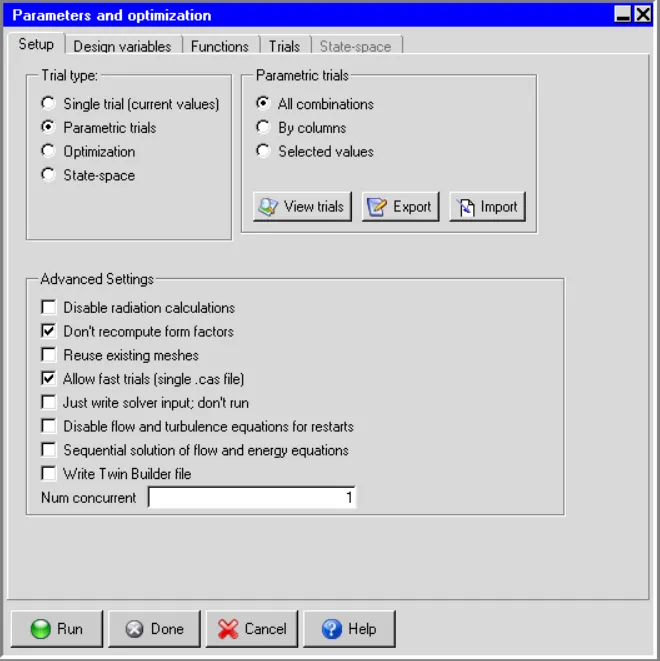
Now define design variables from 100 to 600 with an interval of 100.
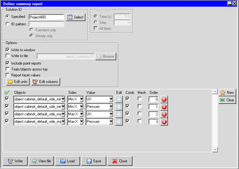
Create summary report for X-velocity and pressure at minX and maxX faces of cabinet.
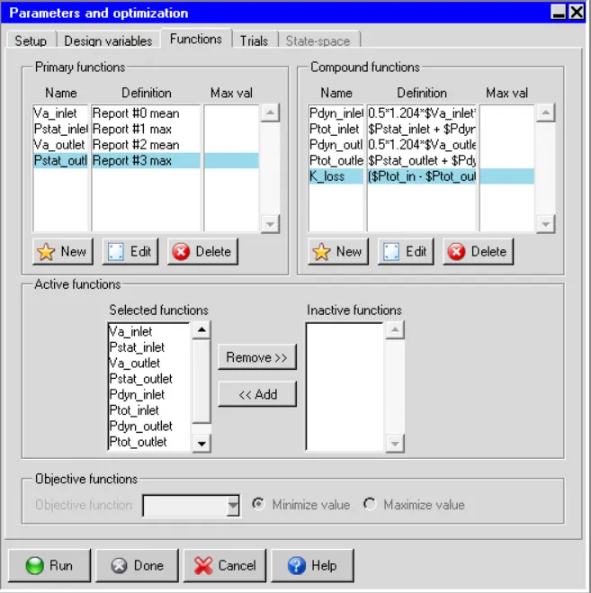
Now, to define velocity and static pressure at inlet and exit as primary functions.
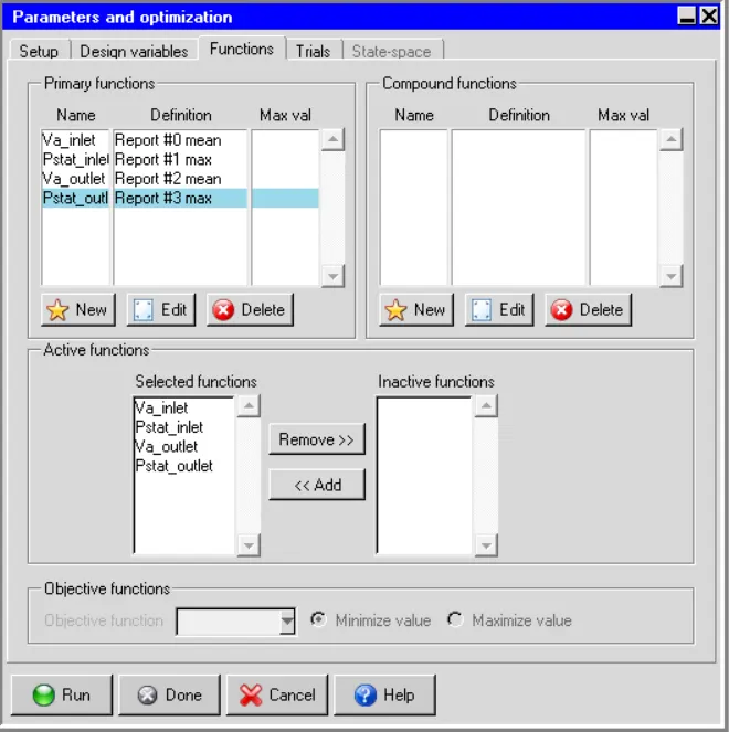
Define dynamic pressure, total pressure and loss coefficient as compound functions.
Step-8: Set up problem.
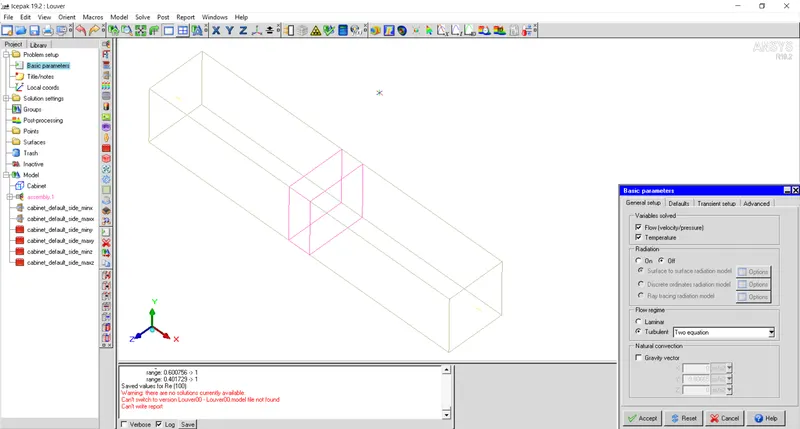
Turn off radiation and select turbulent with zero equation.
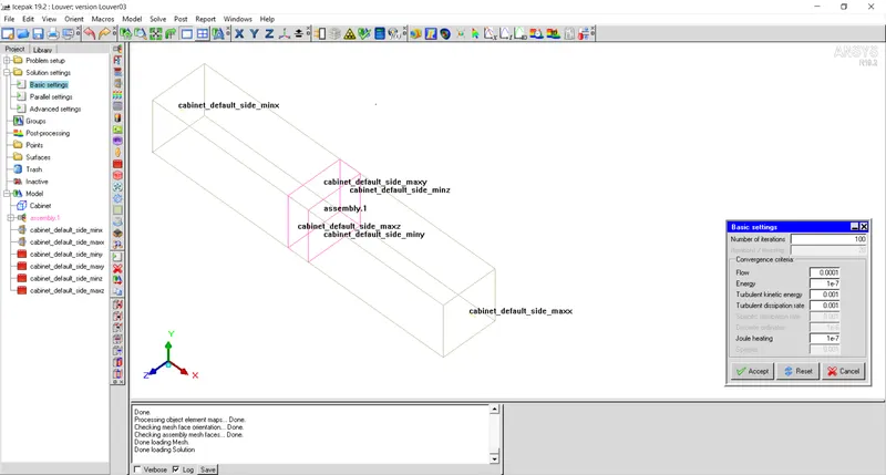
Set number of iterations as 100 and flow convergence criteria as 1e-4 for better accuracy of results.
Step-9: Run the simulation.
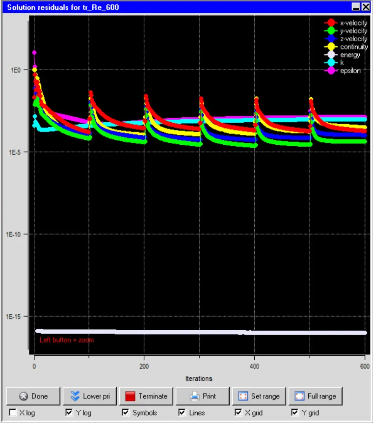
Residuals plot:
Results:
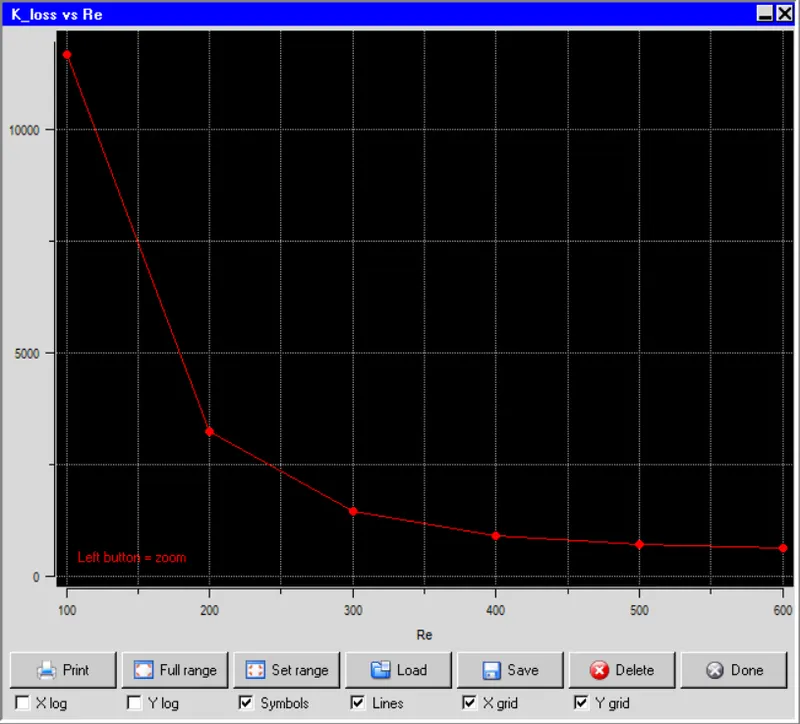
Conclusion:
From figure it can be observed that loss coefficient is having very large value at low velocity but decreases drastically with increase in speed.