Week 5.2 - Multi Level Meshing
AIM: To create multi-level meshing for CAD objects in the model.
In this challange optimal mesh is generated using two common technique called 'seperate mesh generation' and 'multi-level mesh'. Seperate mesh generation is used to reduce mesh bleeding from the assembly to the fluid domain. It reduces the mesh count in fluid domain. Multi-level meshing is used to mesh complex CAD shapes properly without increasing mesh count significantly. Following procedure explains how to generate proper mesh using 'mesh seperately' and 'multi-level meshing' that will not only mesh complex components properly but will reduce mesh count significantly.
Unpack 'HangingNode.tzr' file in ANSYS ICEPAK.
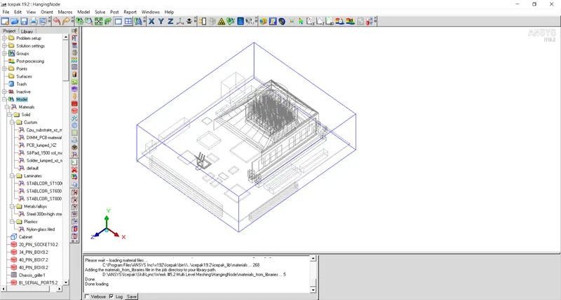
Mesh is generated using the pre-assigned parameters. The number of mesh elements is 713114.
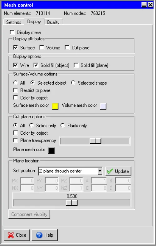
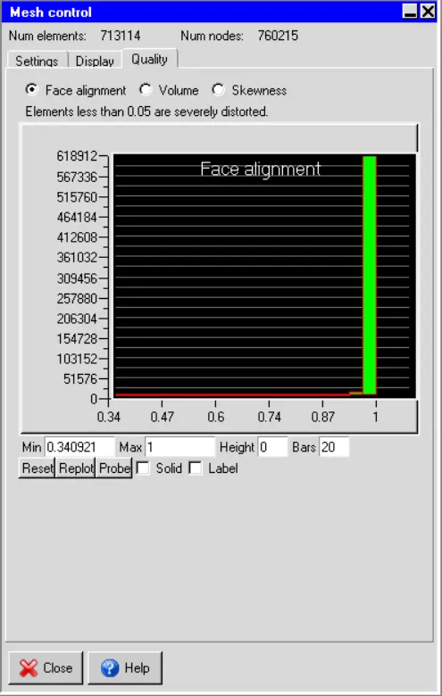
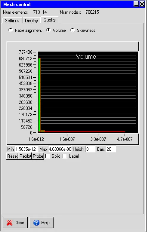
Quality of Mesh:
Face alignment
Volume
Skewness
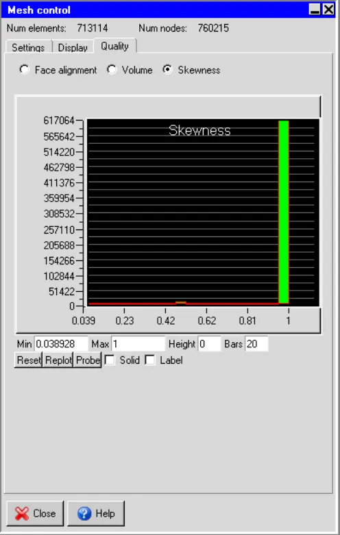
Visible Inspection of Generated Mesh:
The model contains two CAD geometries: 1. guide_sweep-0_1.1 and 2. SheetMetal_HS. Due to complex shapes of the components they are not meshed properly as shown below.
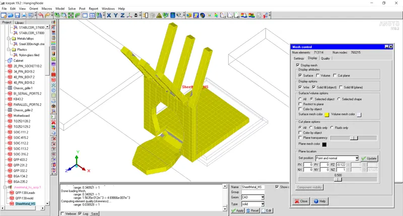
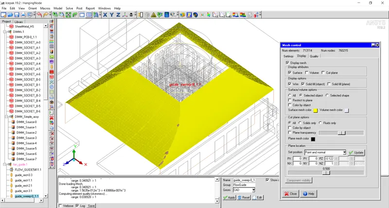
Also, generated mesh is checked inspected on the three orthogonal planes as shown below.
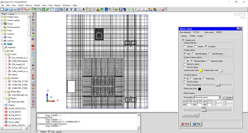
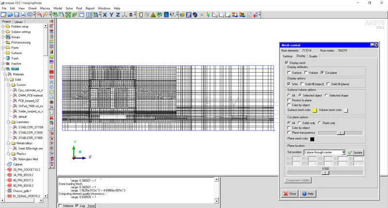
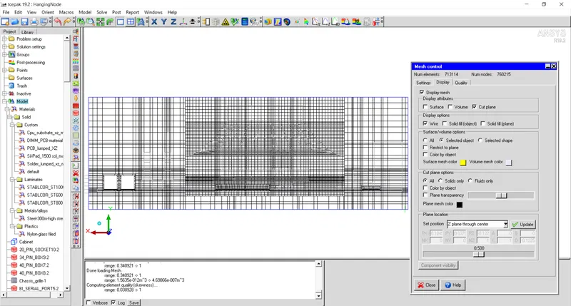
From above images it can be seen that mesh is bleeded in the domain from small components of the model and hence increases mesh count unnecessarily.
In order to reduce the bleeding of mesh from the smaller components in the model, assemblies are created and meshed using 'Non-Conformal Meshing' technique.
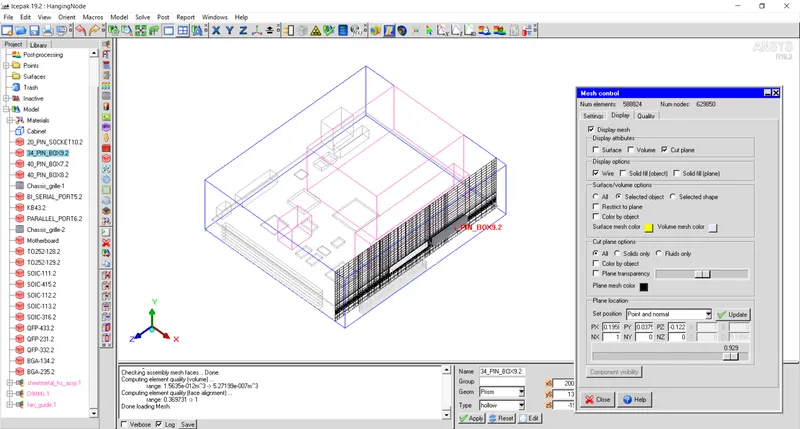
Assembly with name 'DIMMs.1' is meshed seperately and that resulted into total number of elements to be 588824 as shown in figure below.
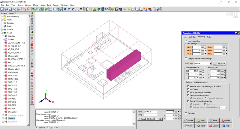
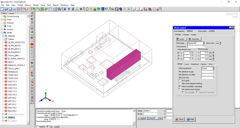
From visual inspection, it is seen that mesh gets bleeded from components '34_PIN_BOX9.2', '40_PIN_BOX7.2' and '40_PIN_BOX8.2'. Hence, an assembly is created from these three components.
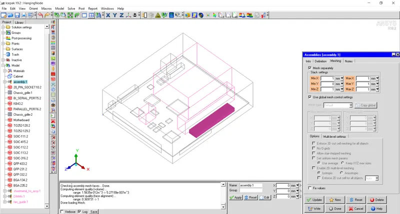
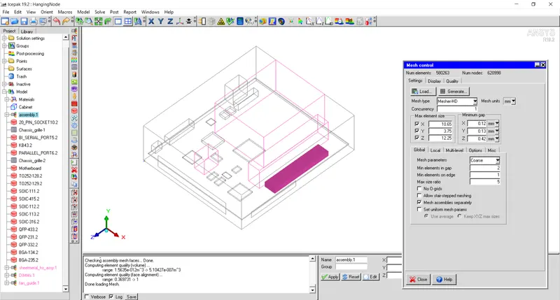
Above assembly is meshed seperately and the total number of mesh count gets reduced again to 580263.
From given model, it can be seen that it contains two components that are not part of ANSYS Icepak premitive blocks or are CAD objects. CAD objects with intricate shapes namely 'SheetMetal_HS' and 'guide_sweep-0_1.1' as shown in figure below.
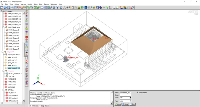
From visual inspection, it can be seen that within entire assembly that includes the above CAD geometry, fine mesh is created inside entire assembly and that has resulted into large number of elements within those assemblies.
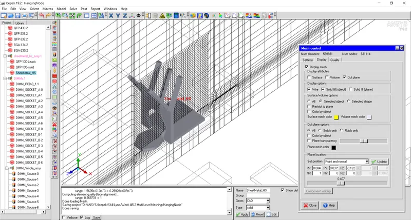
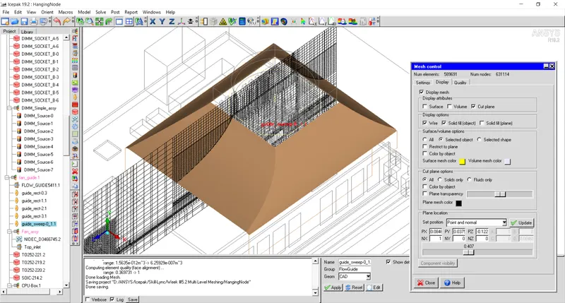
Fine mesh is required within the adjacent space of the CAD model and in the remaining space, one can have relatively coarse mesh and can reduce the number of elements.
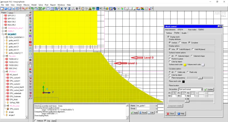
Multi-level meshing allows to capture complex geometry by creating finer mesh in within the complex shapes. The mesh generated can not be even bleeded within the assembly.
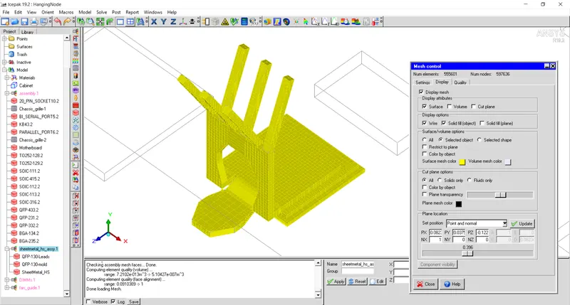
Multi-level mesh is generated for the assembly that contains 'SheetMetal_HS' component. Also maximum element size is set to be 2mm to reduce unnecessary mesh in the assembly.
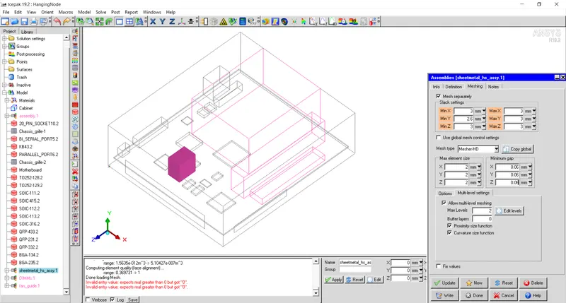
Mesh count is further reduced to 555601 as shown below.
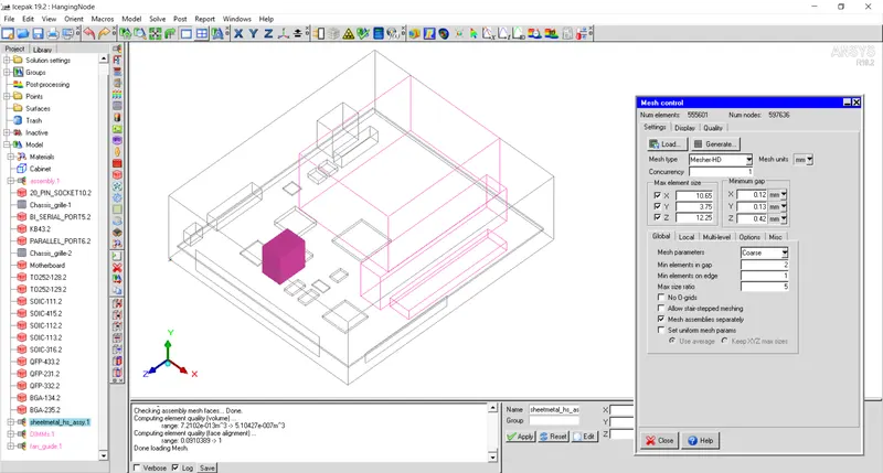
From visual inspection of sheet metal part it can be seen that it is meshed properly.
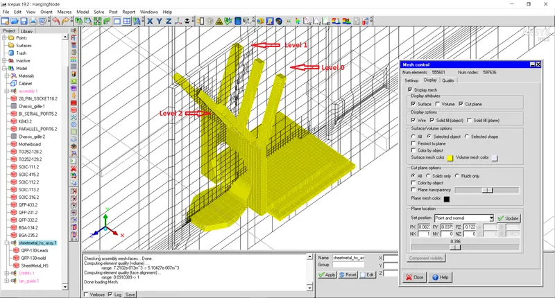
Also, multi-level mesh can be observed from the cut plane.
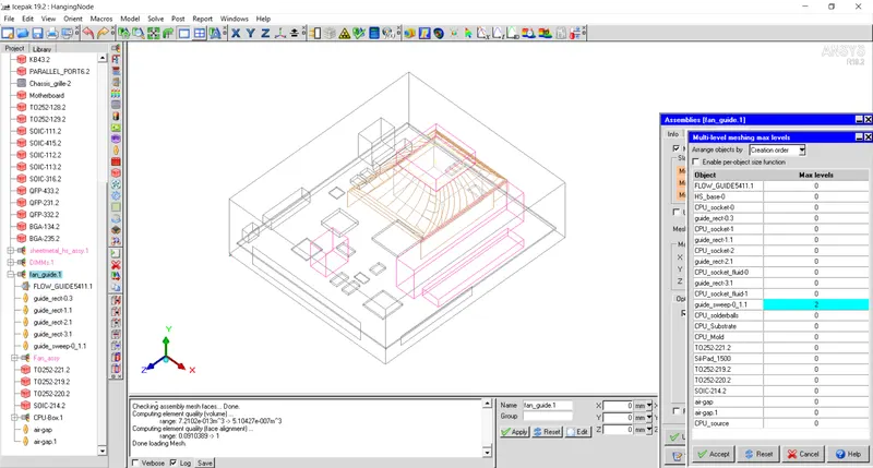
Similar proceducre can be implemented to mesh guide_sweep properly. Multi-level mesh is generated for assembly that contains guide_sweep.
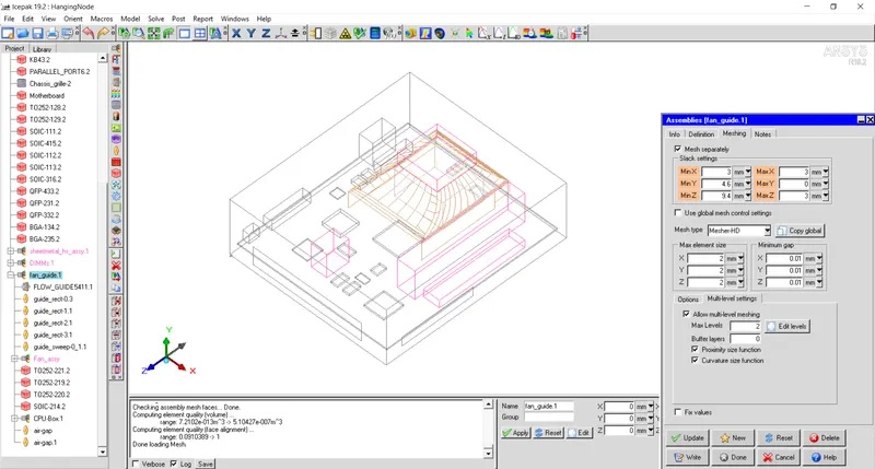
In order to further reduce the mesh count, 'CPU-Box.1' assembly is meshed seperately.
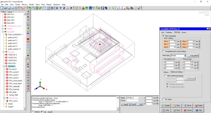
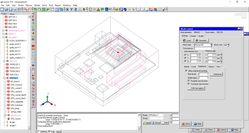
Mesh count is further reduced to 456422.
Fan guide assembly is meshed with Multi level meshing and Level-1 is set for guide sweep.
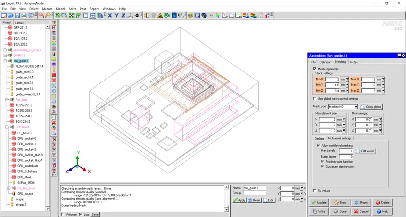
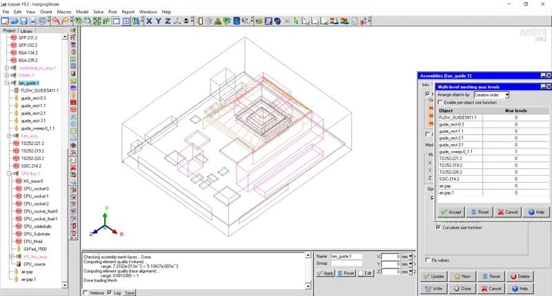
Mesh generation count is increased to 479214. Using multi-level meshing technique, mesh count is increased by using same parameters for maximum element size.
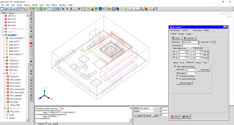
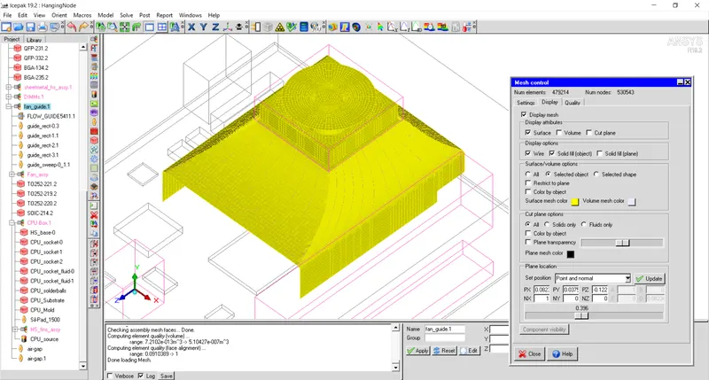
Generated mesh for guide sweep is shown in figure below. It can be seen that proper mesh has been generated for guide sweep.
Mesh levels can be observed from the cut plane through the assembly as shown below.
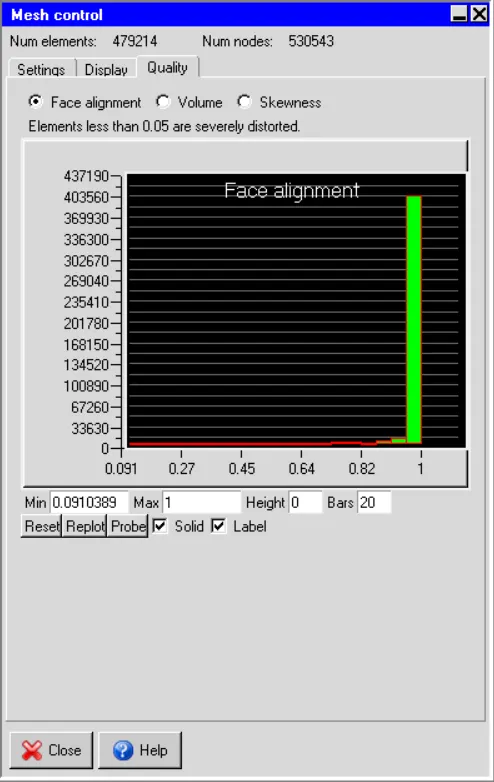
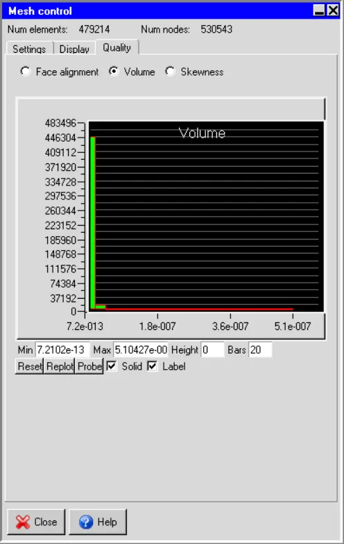
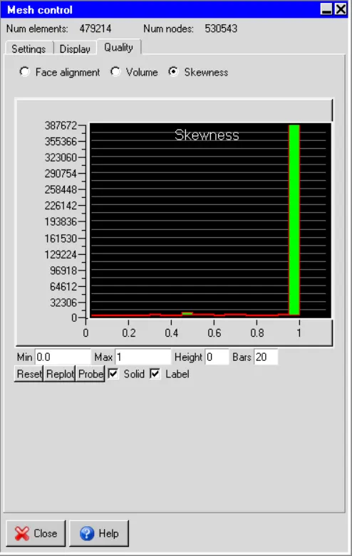
Quality of Mesh:
Face alignment
Volume
Skewness
Conclusion:
From above discussion it can be noticed that proper mesh is generated for complex CAD shapes that are not part of Icepak primitive shapes. Using mesh seperately one can reduce mesh count by preventing mesh bleeding from the assembly. It reduces unnecessary mesh in the model.
To generate proper mesh for complex CAD shapes, reducing the maximum size increases the mesh count sigificantly. Instead one can generate multi-level mesh that will reduce the mesh size near the complex shape of the component and will not affect mesh in the remaining part of the assembly. In this way, one can have larger mesh in the assembly and finer mesh near the complex CAD shape.
From mesh quality it can be observed that mesh quality has been reduced.