Week 5.3 - Forced convection Analysis
AIM: To carry out the complete simulation for given geometry using ANSYS Icepak.
Simulation is carried out for the electronics enclosure given in the challange. A 2D fan is used to create a flow of air over the electronics packages that generates the heat. To efficiently maintain flow of air within the enclosure, grills are provided on the two sides of the enclosure. To remove heat from the sides of the enclosure, fins are attached on the enclosure sides near the transistors. A steady state simulation is carried out by considering real life parameters for all the components as discussed below.
Step-1: Geometry Simplification
- Import 'DME.stp' in Ansys workbench geometry.
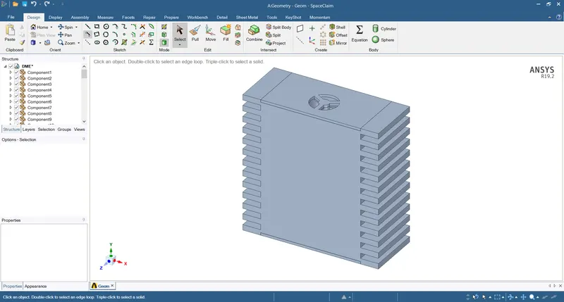
- Hide enclosure to simplify the assembly.
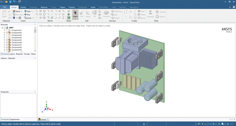
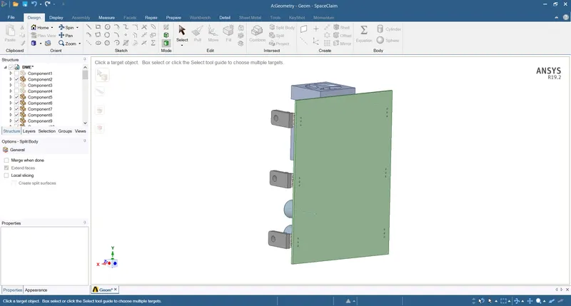
- Split and remove all the pins of the transistors by the top plane of PCB, as it will not affect the simulation.
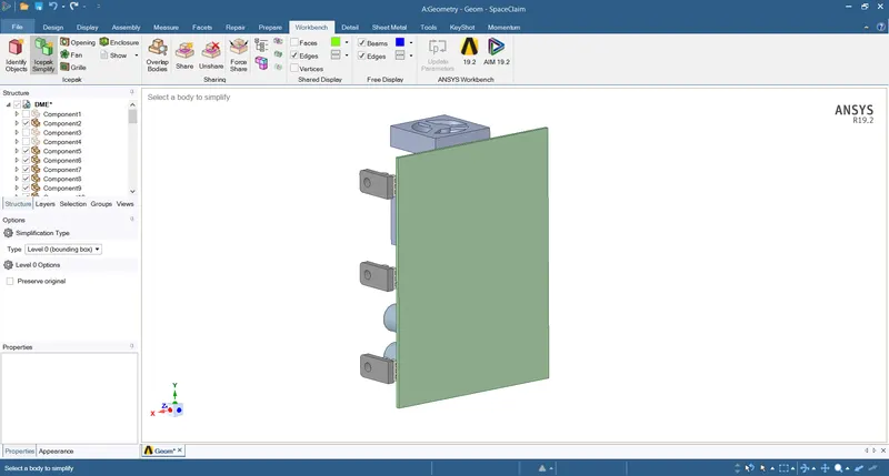
- Simplify PCB with Level-0 (bounding box).
- Remove all the fillets and chamfers in the model except the transformer.
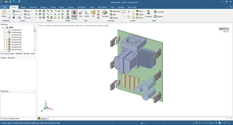
- Fill all the cylindrical holes in transistor metal part.
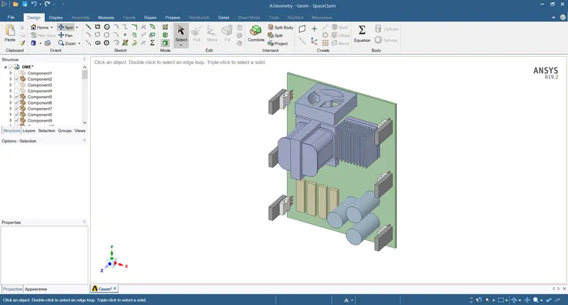
- Fill all the semi-cylindrical hole on the edges of the transistor bodies.
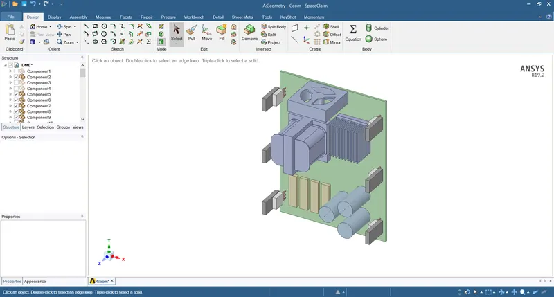
- Simplify all the pins of transistors using Level-1 (bounding box).
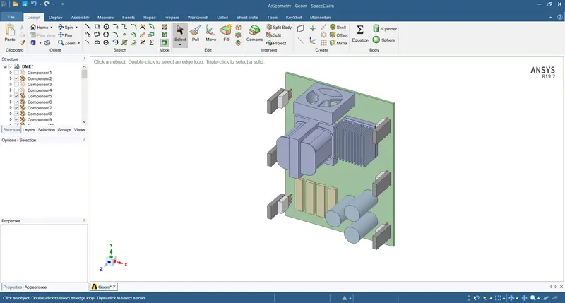
- Simplify all the transistors, capacitors and other cubical objects using Level-1 (cuboid, cylindrical fit).
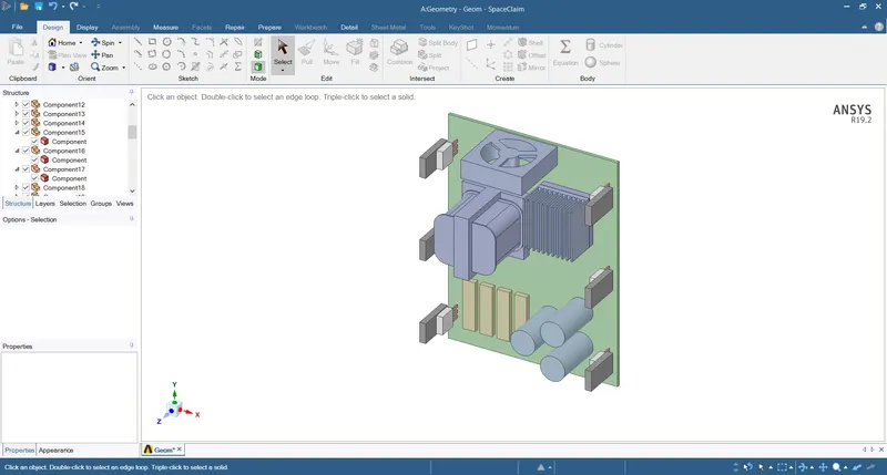
Check icepak objects.
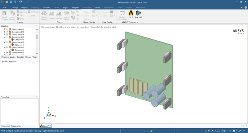
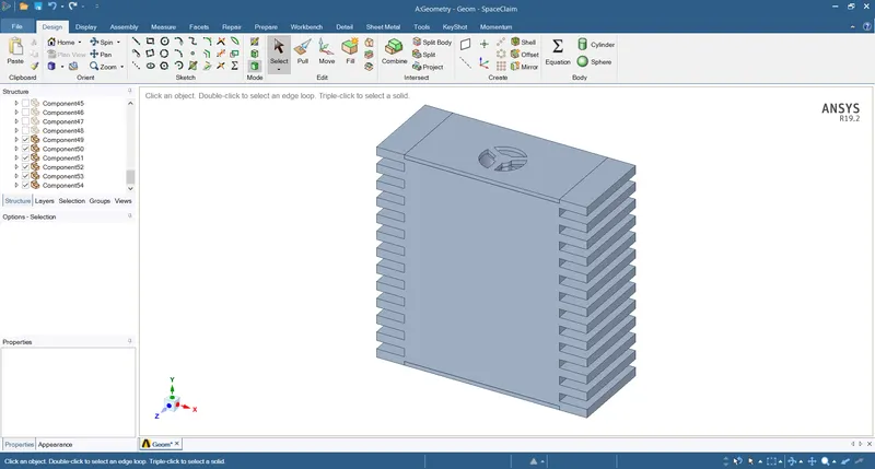
- Simplify BGA with Level-0 (bounding box) and BGA Heat Sink using Level-2 (polygon fit).
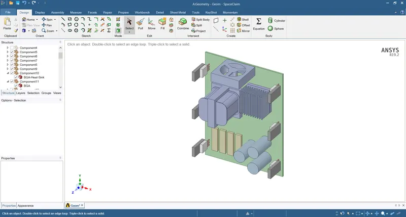
Icepak objects:
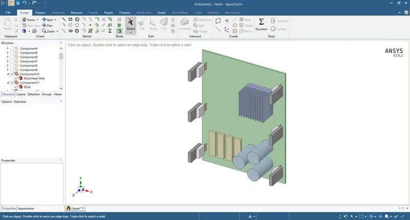
- Convert all the coils into Icepak objects using Level-3 (CAD object).
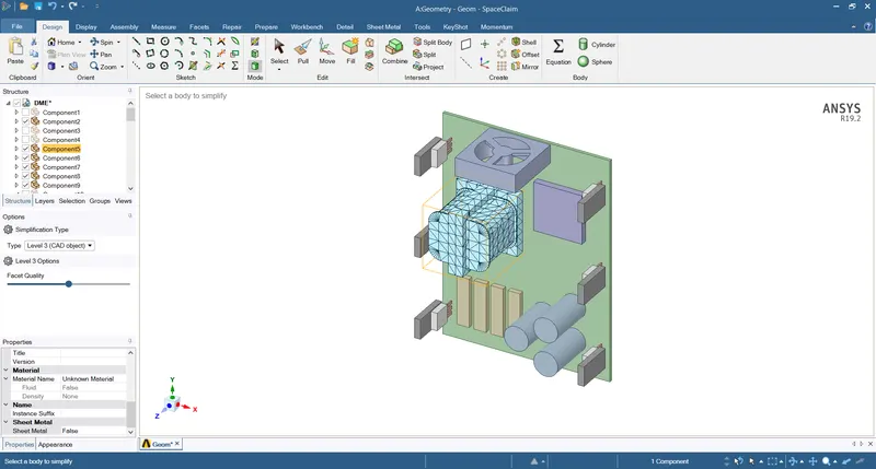
Icepak objects:
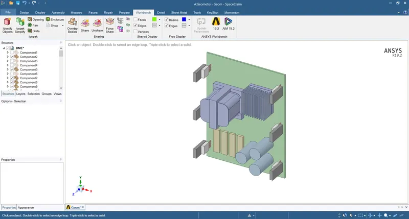
Non-Icepak objects:
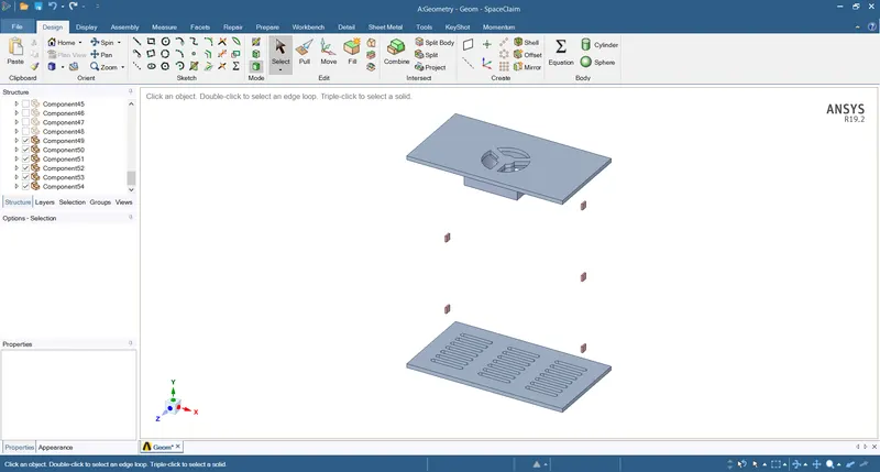
- Simplify all the dies of transistors using Level-0 (Bounding box)
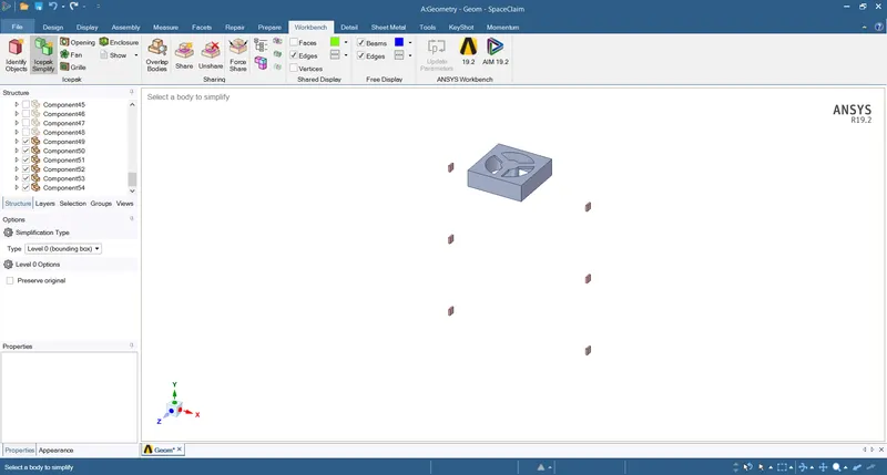
Icepak objects:
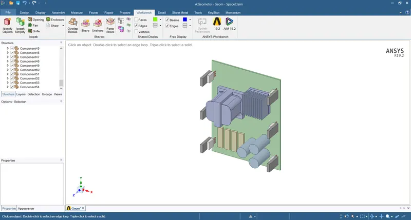
Non-Icepak objects:
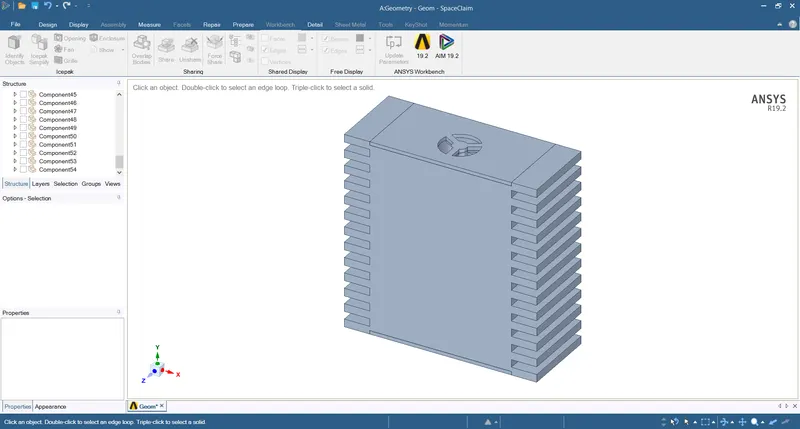
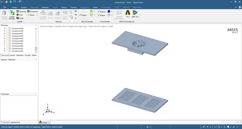
- Delete 3D fan, 2D fan will be created in Icepak instead of 3D.
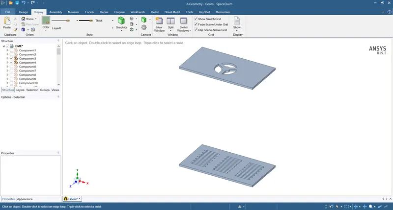
Except enclosure, all the objects are Icepak objects.
- Split and remove all the support on the enclosure, as it will not affect simulation.
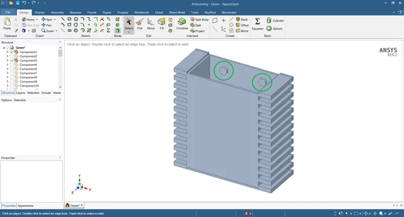
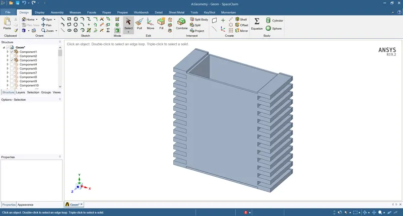
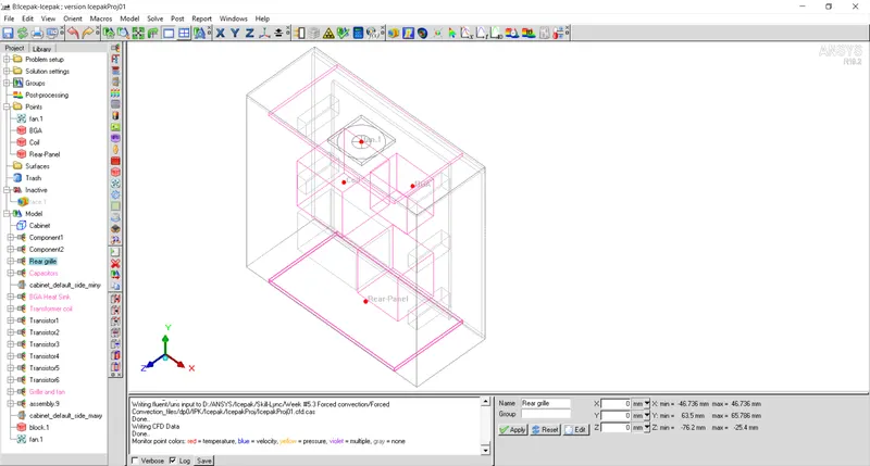
- Create a hollow prismatic block that will act as a fan case.
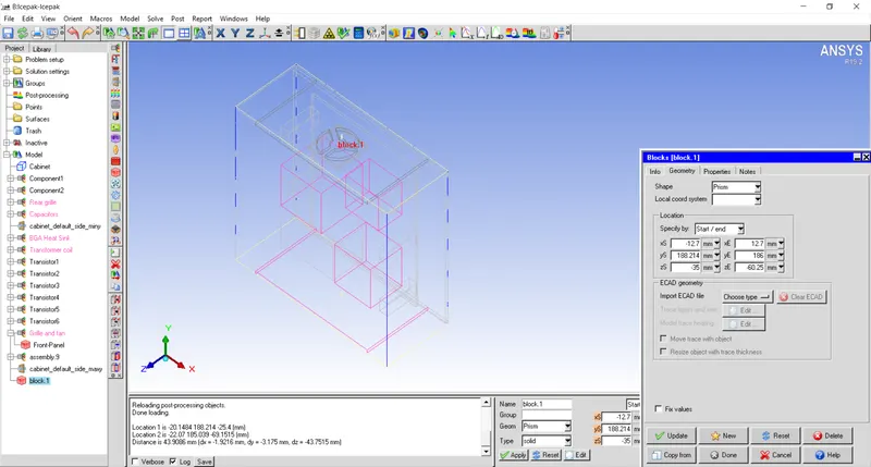
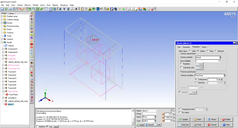
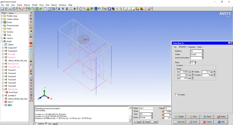
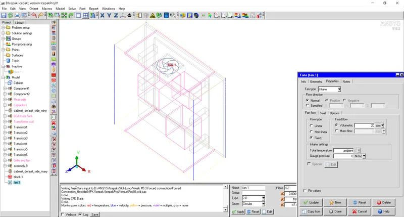
- Create a 2D fan with OD 25.4mm and ID 10mm. Set constant flow rate of 20 CFM.
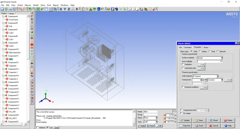
- BGA is assigned total power of 30W.
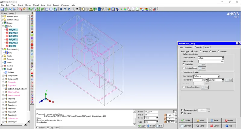
- All the 6 dies of the transistors are assigned total power of 4W.
- Monitor points are created at following points: 1. fan center, 2. coil center, 3. Return grille and 4. BGA center.
Step-2: Mesh Generation
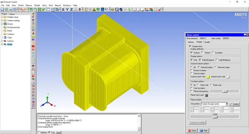
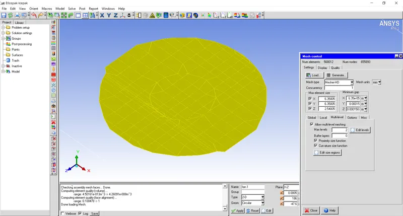
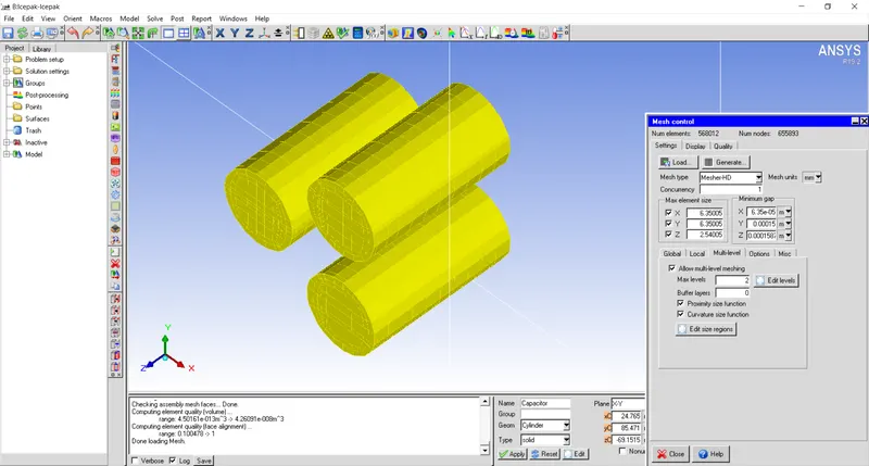
Mesh is generated by creating seperate assembly. Multi-level meshing with Level-2 is created for Transformer coil and intake and return grille. Visual inspection is done for the CAD objects as shown below:
No of elements: `568012`
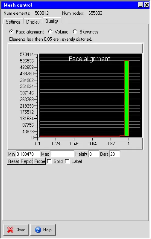
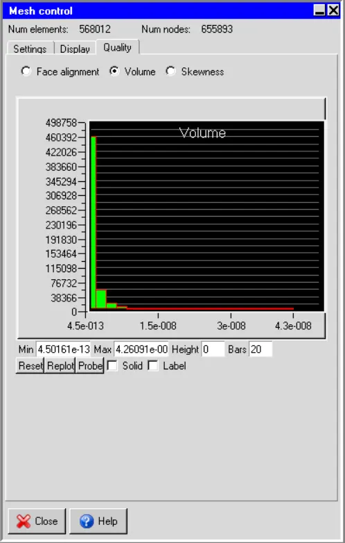
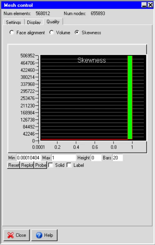
Mesh quality:
Face alignment: `0.1`
Min volume: `4.5e^-13`
Skewness: `0.0001`
Step-3: Solver Set-up
Steady state simulation is performed without considering radiation.
Flow as well as temperature field is generated by solving energy and momentum equation within the domain.
Ambient air is having temperature of `20^oC`
No of Iterations : `1000`
Temperature history is plotted at the four monitor points as described above. From the following history plot, it can be seen that the steady state condition has been reached at the four monitor points.
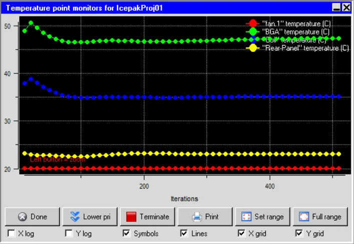
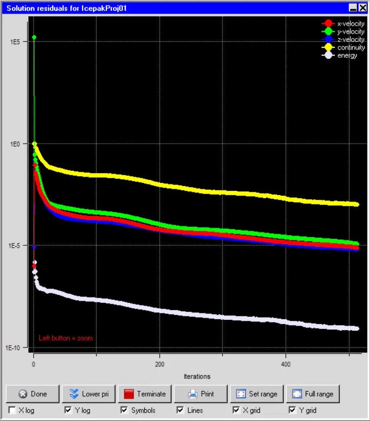
Residual plots are also plotted for velocity and temperature within the domain. It can be seen that steady state has been achieved after around 510 iterations.
Step-4: Results and Discussion
Temperature contours on object faces
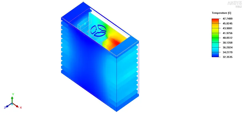
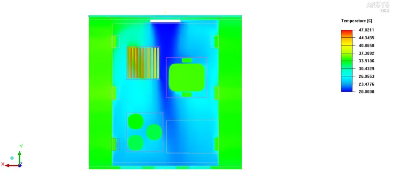
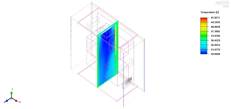
From figure below it can be seen that maximum temperature of `47.7489 ^oC` is observed near the BGA package as maximum heat is generated inside BGA package. Also, higher temperature than the ambient air is observed at the dies of the transistor as it generates heat of 4W.
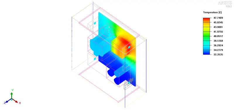
Higher temperature is observed on the sides of the enclosure as transistors generate heat that are placed near that fins.