Week 11 - Final project
DEVELOPMENT OF DOOR TRIM PANEL
Automotive Plastic Trim:
Automotive plastic trim design is the ground of the plastics manufacturing industry. In industry, Proper design is very important & crucial before it goes for tooling as it saves huge costs in the product life-cycle. The design of Automotive Interior and Exterior plastic components is called Trims. The plastic components that you see inside the car are the Interior. Ex: Dashboard, Instrument Panel, Doors, seating, and pillars. Plastic components that you see outside of a car are Exterior. ex: bumper, light assembly, hoods.
Door Trim:
The door panel covers internal parts like the window regulator, the power window motor, and the wiring. It is attached to the sheet metal part of the door. It is designed differently based on the design of the sheet metal part of the door. Besides its aesthetic look, it also has many functional features attached to it such as an armrest, bottle holder, speaker attachment, etc. In older cars, door panels used to be made out of cardboard and upholstered with material that matches the rest of the upholstery within the cabin. On the other hand, most modern cars have door panels made from plastic. The main materials used include kenaf, which grows year-round and has excellent CO2-absorbing properties, and plant-derived plastic, making them environmentally friendly as well.
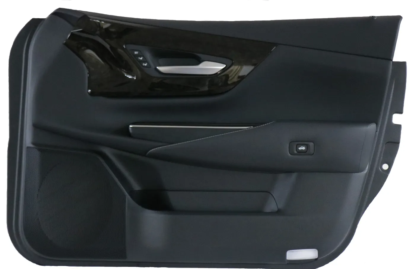
fig.1, door trim produced by Toyota.
fig.2, door trim along with full door segment.
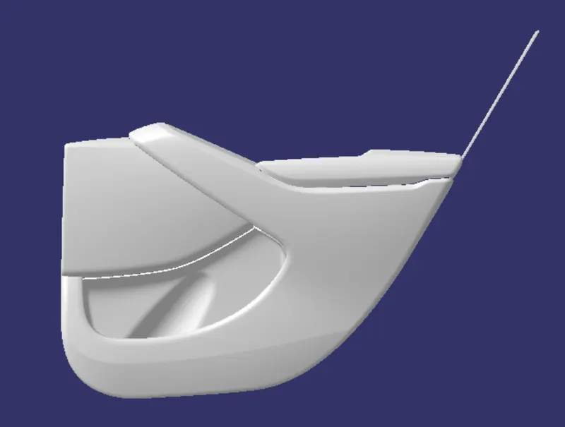
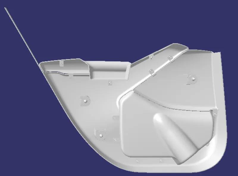
fig.3, Designed plastic component.
Aim:
To design a car door plastic trim, by following industrial design standards.
Abstract:
This project demonstrates the steps and procedures required to create a plastic door trim for a car's door, provided a Class A surface created by the concept sketch team. This project includes the creation of a tooling axis for each trim part, creating a proper b surface with required attachment features, creating a C surface which satisfies the draft conditions, and finally creating a solid from the surface created. It also explains the draft analysis performed to check the manufacturability of the products using injection moulding. Various plastic door trims such as a map pocket, an armrest, a lower substrate, etc were successfully developed in this project.
Tools Used:
Part workbench:
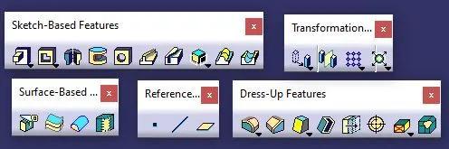
fig.4
Surface Workbench:

fig.5
Given:
Class A Surface:
In the Automotive industry, there will be a dedicated team who will perform the aesthetic designing of various components including the whole vehicle. They will create various concept sketches after ideation. After that, they will also create a Class A surface of the product. This class A surface is then passed over to the NPD CAD team. They will initially inspect the Class A surface in order to check if the design is manufacturable or if it is following the engineering principles. If there are any issues with the design, they will contact the product design team and will ask to modify the Class A surface in order to solve the problem. Here I received the Class-A surface as shown below.
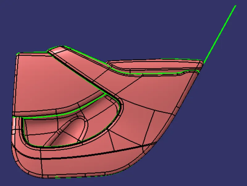
fig.6, A surface (whole)
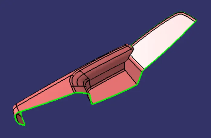
fig.7, arm rest
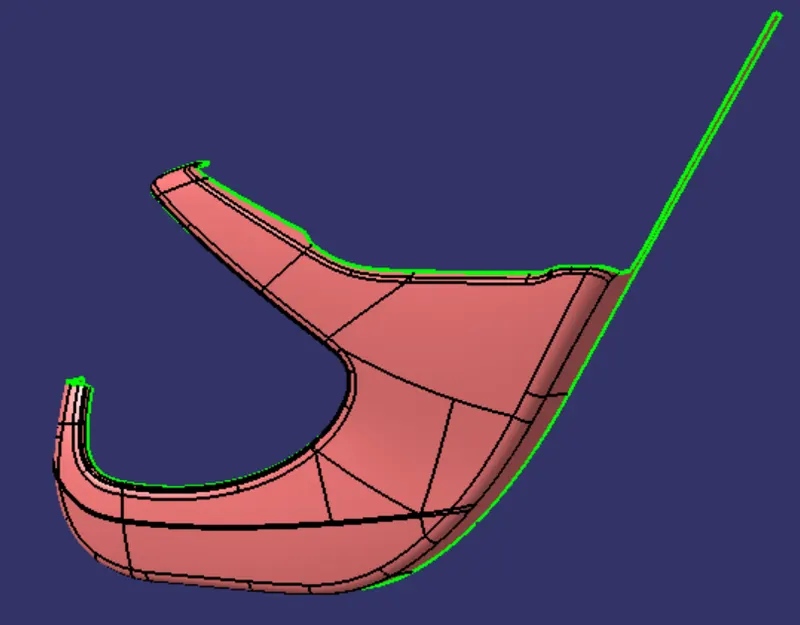
fig.8, lower substrate
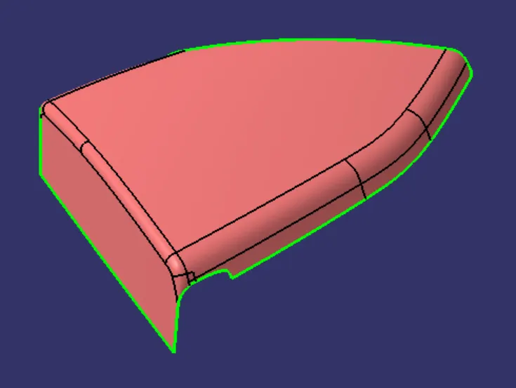
fig.9, map pocket
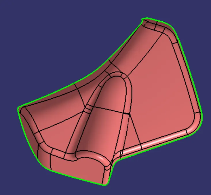
fig.10, map pocket lower
Master Sections:
These are the guidelines provided to a design engineer which describe how a component would/must look like once it is modelled into a solid component from the class-A surface. For example, in this model, we have received a master section as an input which tells us about the thickness of the component and dimensions & type of the engineering features on the component.
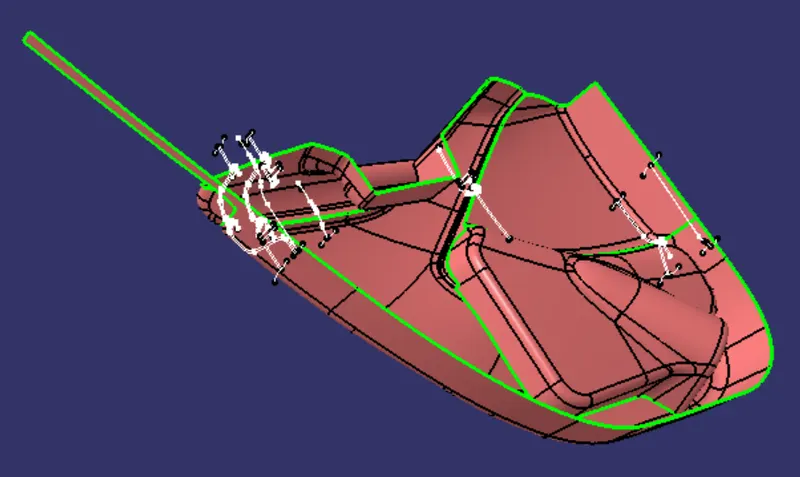
The Sequence of Operation:
- Creation of Tooling Axis and Draft analysis for A-surface.
- Creating B&C surface and Draft Analysis.
- Creating attachment feature on B-Side and Draft Analysis.
Procedure
Tooling axis creation:
The main tooling axis was created by applying a zero distance value on the surface as shown below.
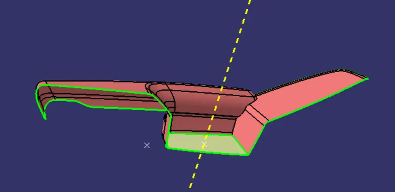
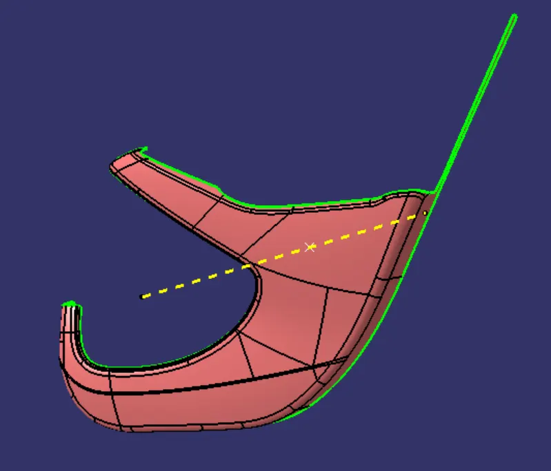
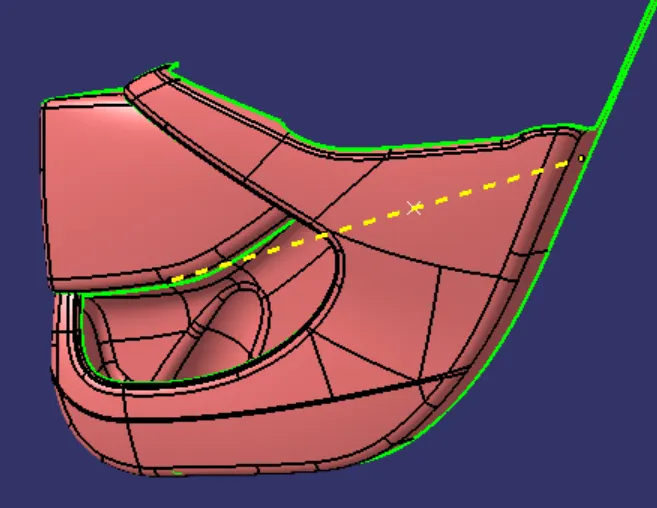
Draft analysis:
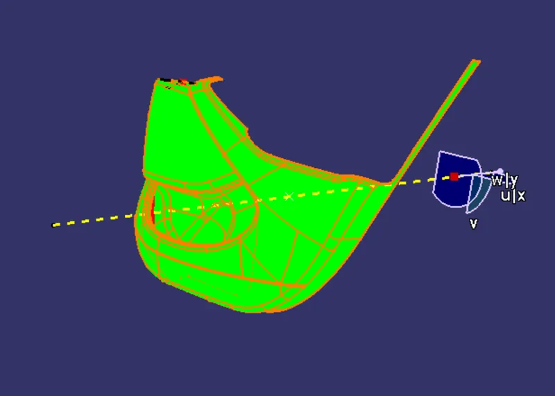
The Draft Analysis for Armrest could not be acquired with the main tooling axis so it is needed to create a separate tooling axis.
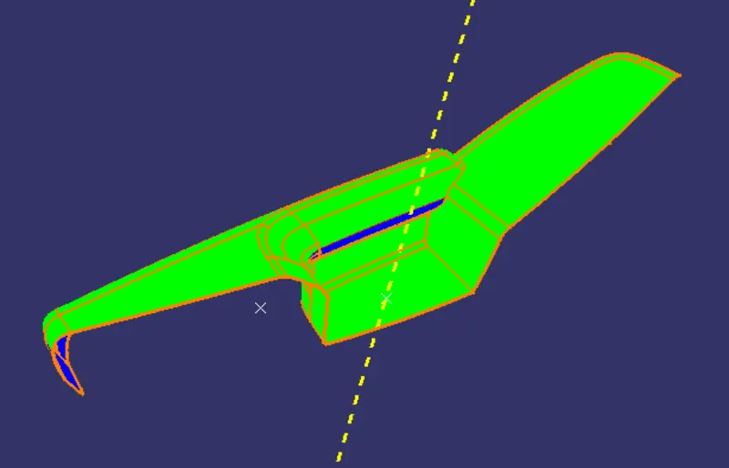
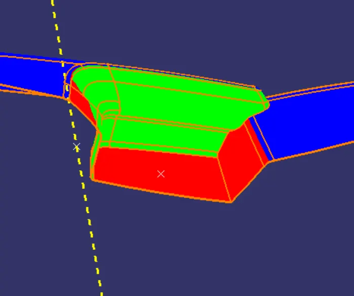
About sliding axis:
Creation of B&C surface:
Eg: Map pocket,
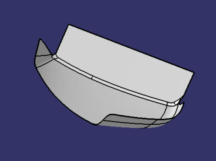
B surface
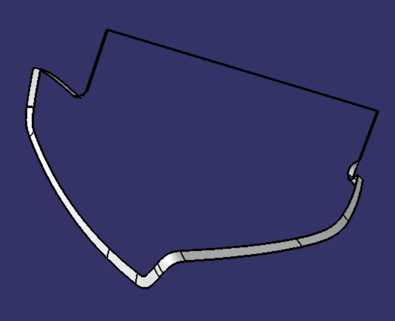
C surface
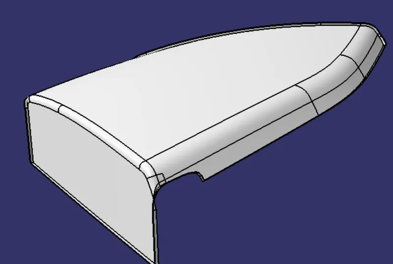
B+C surface
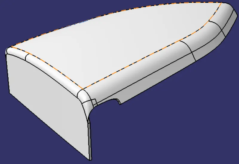
Final surface, A+B+C
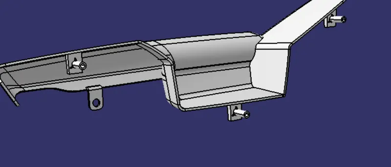
Creation of Attachment features on B surface
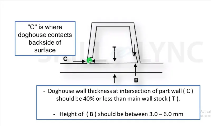
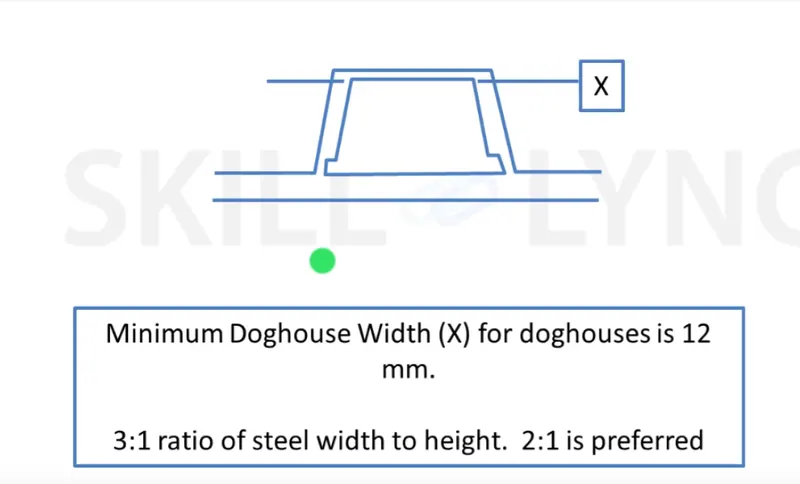
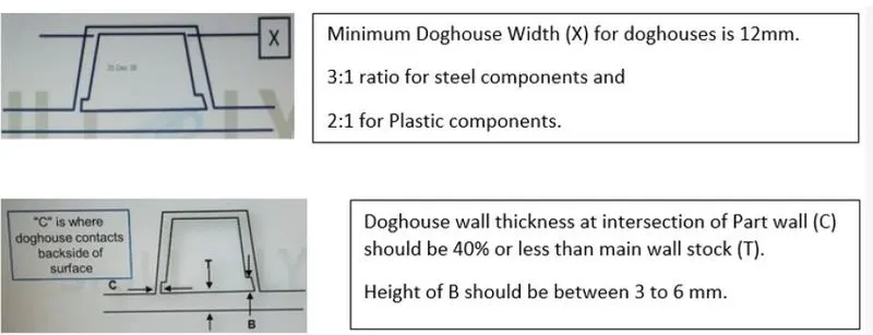
Design rules for doghouse:

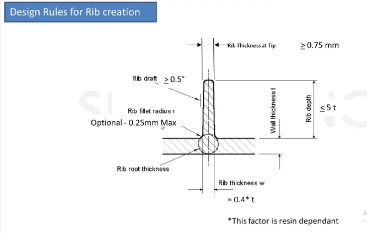
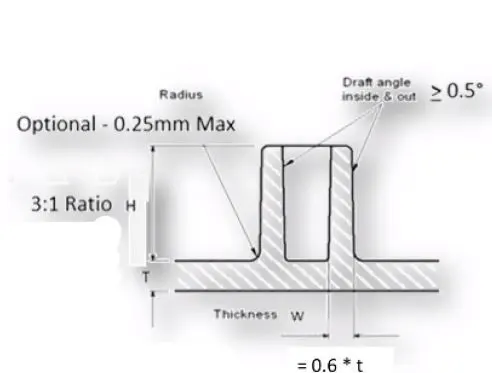
Design rules for Ribs:
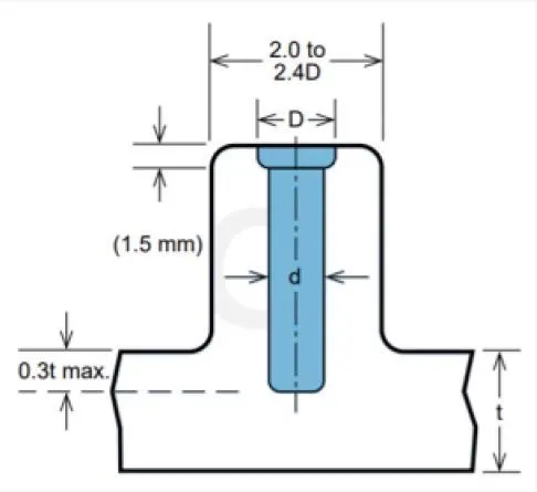
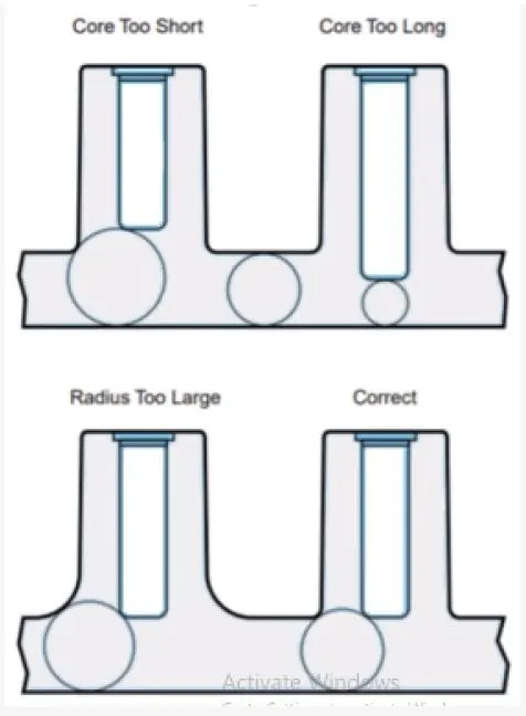
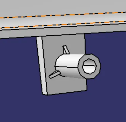
Design rules for Screw bosses:
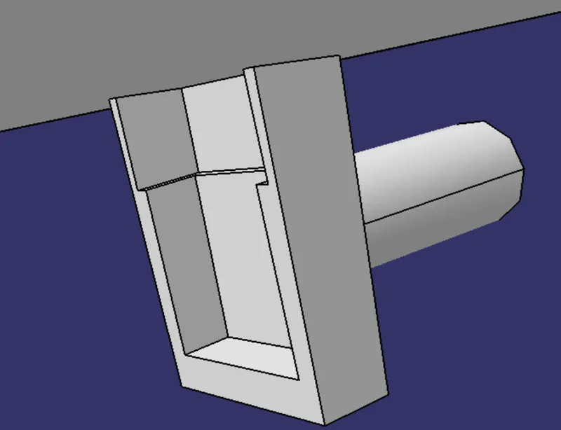
Creation of doghouse:
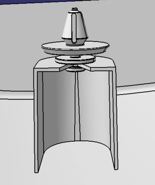
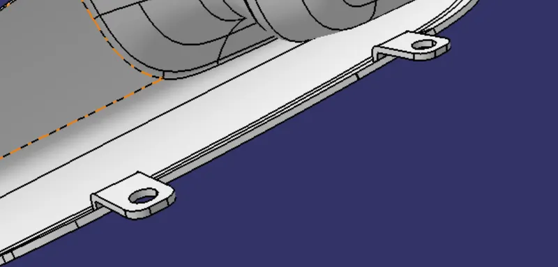
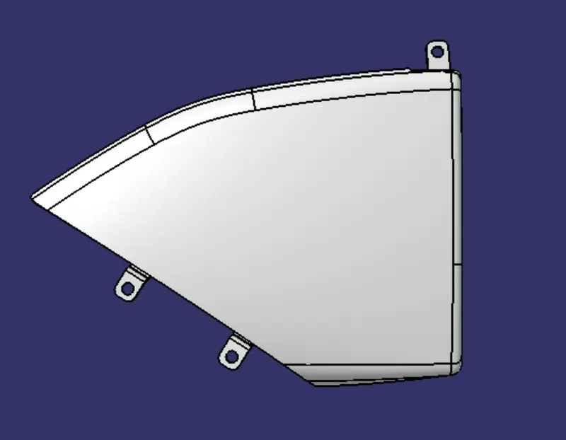
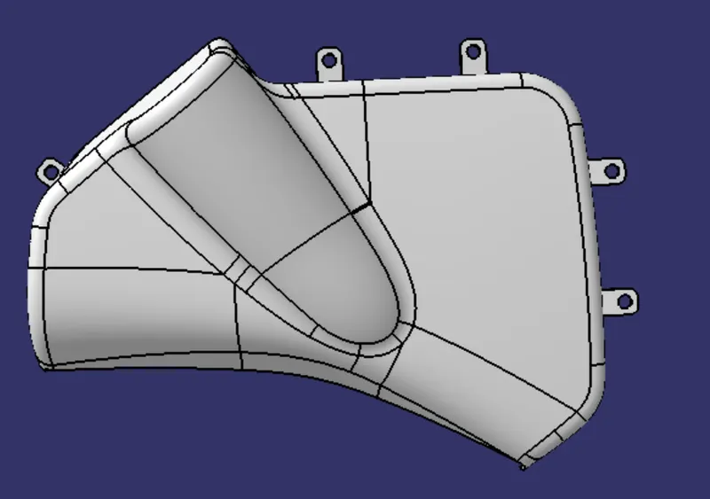
Creation of Flanges:
Creation of heat stakes:
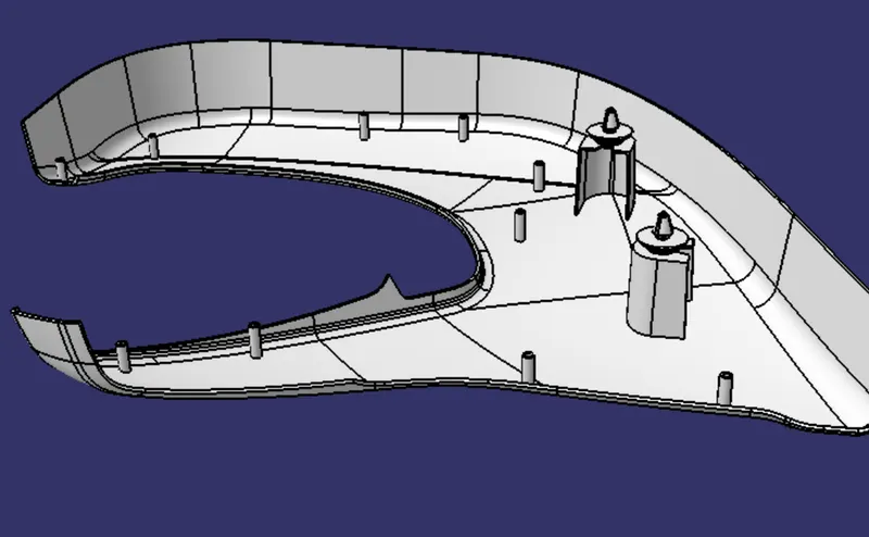
Creation of screw bosses:
Conclusion:
1. The Door trim is created using a generative shape design, Part workbenches.
2. The model is designed with the nominal draft angle of 3 degrees for the component and
0.5 degrees for the Attachment features.
3. The Closed body of the model is created using close body command in part design
workbench.
4. The attachment features in the model are designed following the design rules.
5. The tree structure is maintained clearly.