Week 11 - Final project
Design and development of a Door Trim panel
Aim
To design and develop a Door trim panel from the given Class A surface and follow the Master section provided. To create B-side attachment features by considering the design rules.
Objectives
- To create thickened part by referring the master section.
- To create the mounting features as per design guidelines in the industry and with the master section
- To perform Draft analysis and check manufacturing feasibility
Introduction
The inner door panel is a component used for strengthening the door assembly. It is one of the most essential components on which all accessories are mounted like hinges, glass guide channel, Front door sill, window winding regulator, hard pad, molded trim, latch, etc. The front door inner panel is used for sealing purposes.

As it is a complex part, it is divided into sub-parts to make the design process easy. The sub-parts are divided as
- Armrest
- Upper substrate
- Lower substrate
- Map pocket.
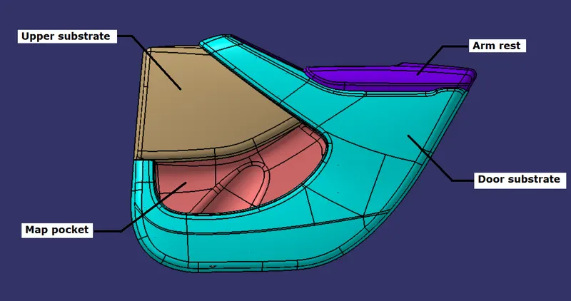
The door currently has an inner full-width panel consisting of electronic windows, central locking system, and speakers. These panels typically consist of a foamed core covered with either textiles or plastics.
Methodology
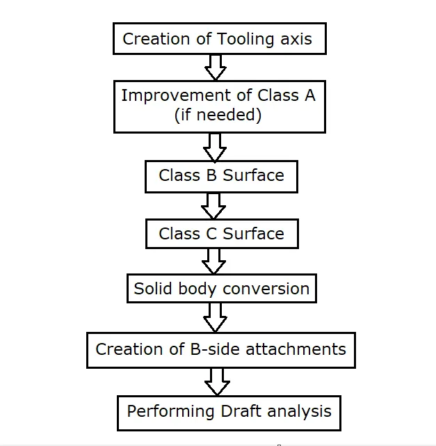
The procedure followed for creating the Interior Door trim panel is the same as followed in the OEMs and Tier-1 companies. First, the Class A surface is divided into sub-parts and the geometrical sets are rearranged. Then tooling axis, improvement of Class A surface, Class B surface, Class C surface, and B-side attachments are created. After this Draft analysis is performed to check the manufacturing feasibility.
Tooling axis and sliding axis
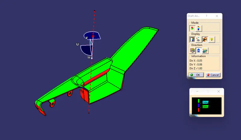
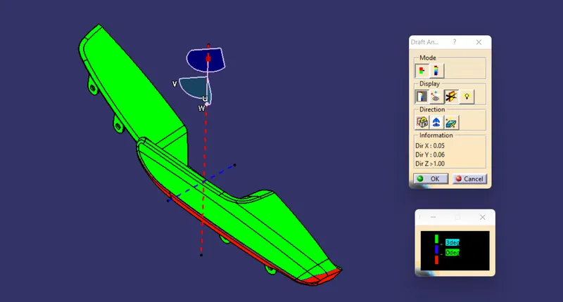
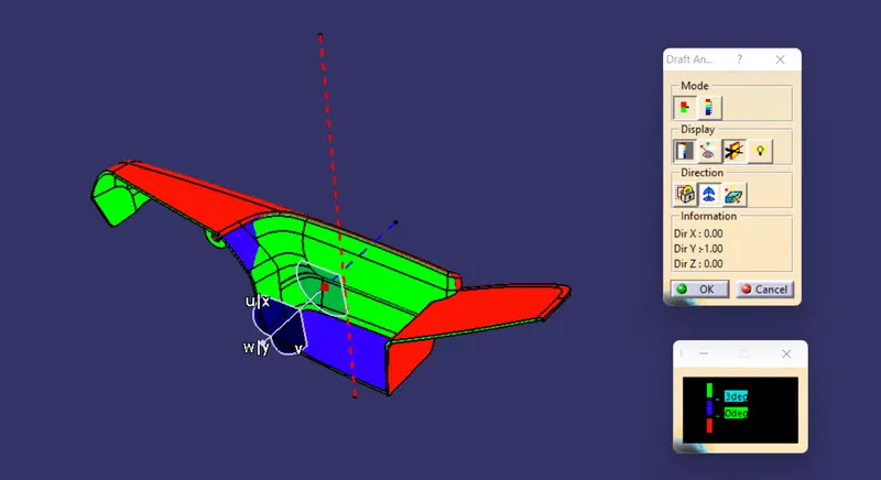
The tooling axis is the direction in which the core and cavity opens and closes. It also gives an idea about the manufacturing feasibility. It is the responsibility of a Design engineer to analyze the Class A surface and find out the best possible tooling direction by keeping in mind that all the draft angle is with respect to the tooling axis so that the component can be easily ejected from the core and cavity. The tooling axis which we create should be able to clear the class A surface in the draft analysis. In some case it is not possible to clear the Class A surface using the Toolong axis. In that case sliding axis (Side core axis) is used to clear the under cut area.
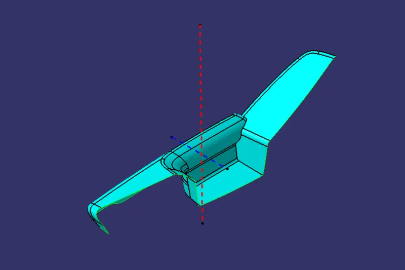
(i) Arm rest
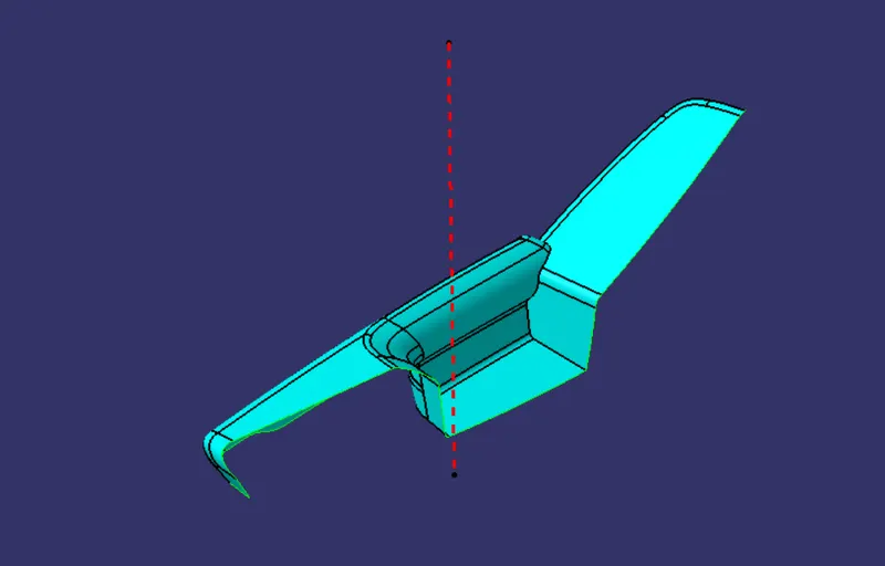
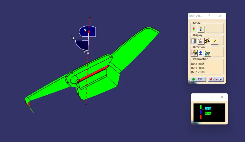
In some areas we can observe that it have under-cut. To clear the under cut areas we have to create a sliding axis.
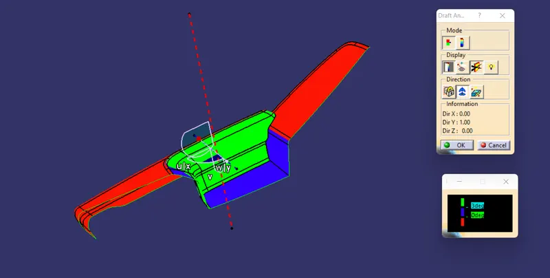
Now, we can observe that the under cut areas are being cleared using the sliding axis.
(ii) Door substratre
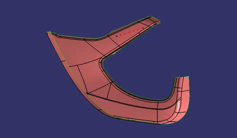
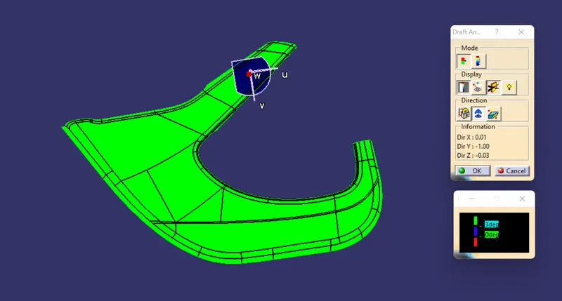
The class A surface is cleared using the Tooling axis.
(iii) Upper substrate
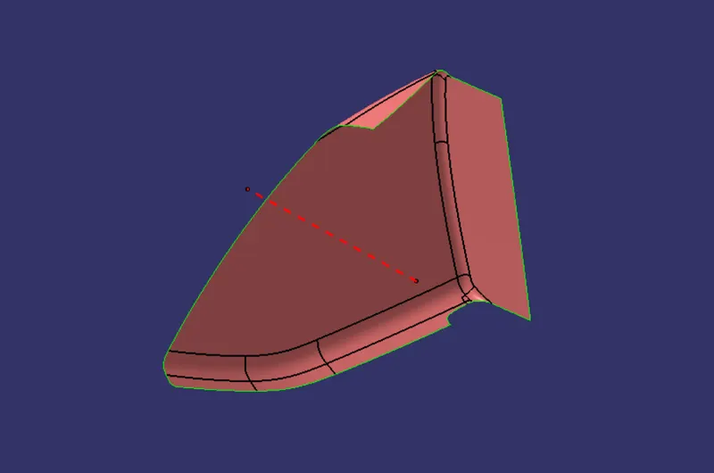
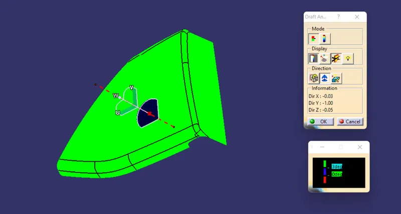
The class A surface is cleared using the Tooling axis.
(iv) Map pocket
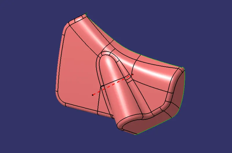
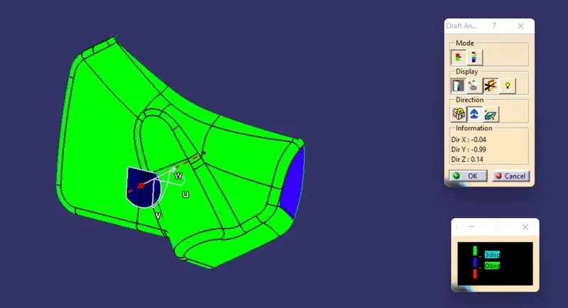
From the above result we can observe that it has a small area which is not getting cleared. But it will not make any problem as it has a positive draft. So we can ignore it.
Class A Surface
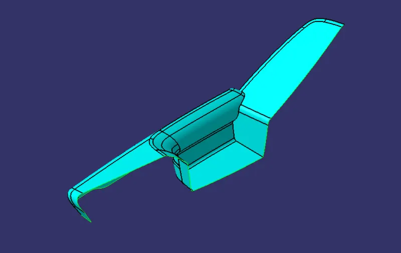
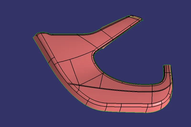
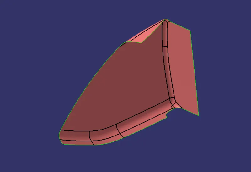
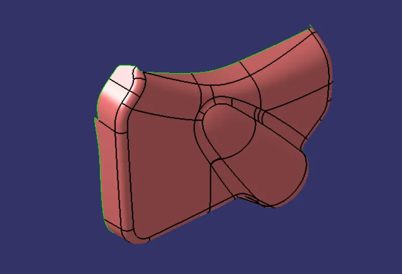
After creating the tooling axis, the quality of the Class A surface provided is checked. If the quality of surface is good, then we can continue with the surface. Incase the quality of the surface is poor or it has patches, then we need to work on the Class A surface.
(i) Arm rest
(ii) Door substratre
(iii) Upper substrate
(iv) Map pocket
Class B Surface
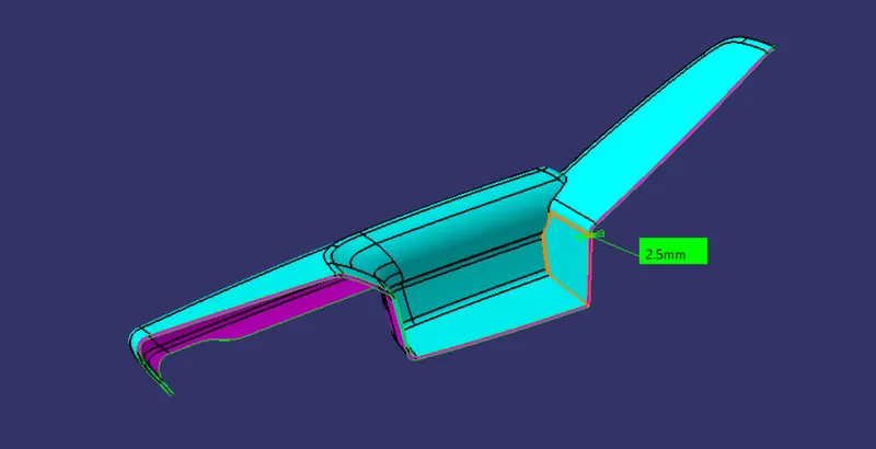
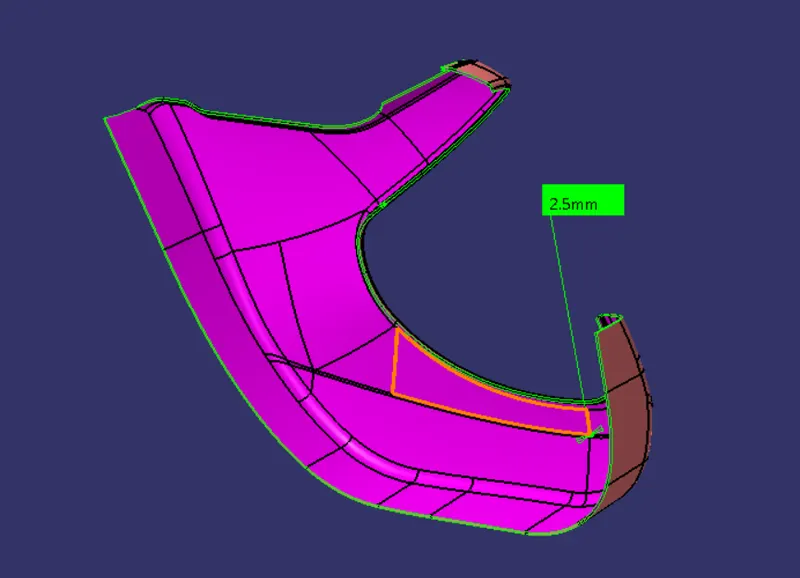
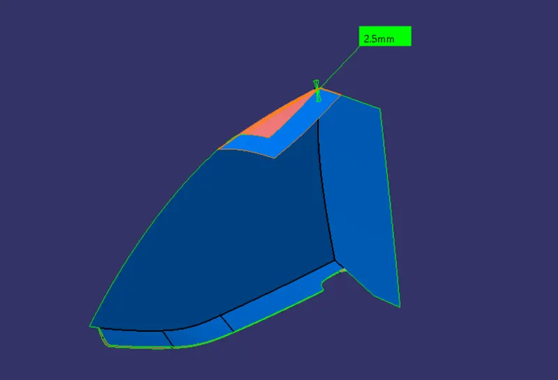
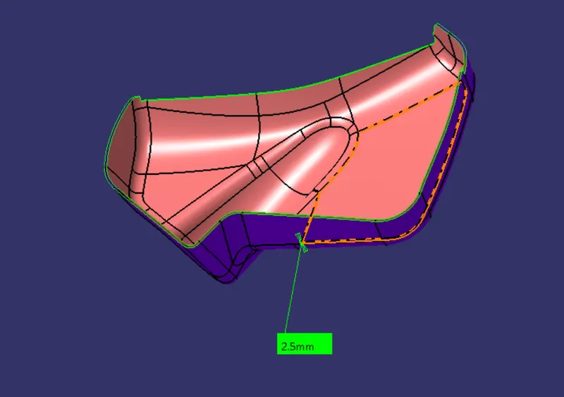
A Class B Surface is an invisible Surface which will not be visible to the viewer. Basically it is the backside of a Class A surface where the attachment featuresblike ribs, snap fits, doghouse, etc will be created. The Class B Surface is created by offsetting the flat surfaces from the Class A surface and trimming it. From the master sections provided we can measure the offset value for Class B surface. Here it is 2.5mm. While creating the Class B surface make sure you are giving the right direction for offset.
(i) Arm rest
(ii) Door substrate
(iii) Upper substrate
(iv) Map pocket
Class C Surface
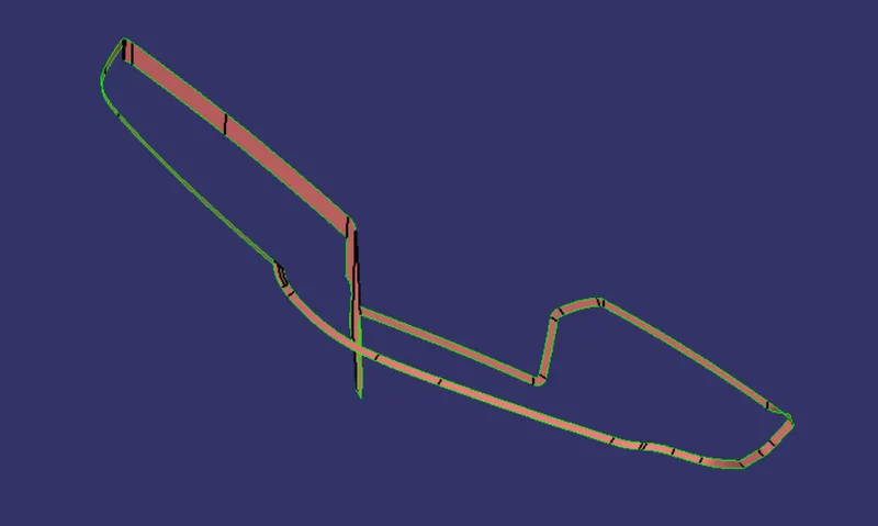
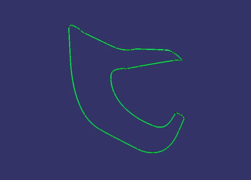
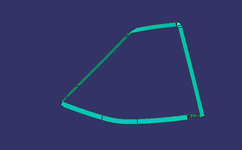
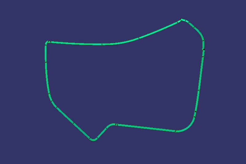
A Class C Surface is connecting surface which joints Class A and Class B surfaces together. The Class C finish allows more imperfections than Class A or B. Class C is often specified for interior surfaces not readily visible, surfaces that will be covered by another part when assembled. Genrally the Class C surface is created using the sweep command. A draft of minimum 0.5 deg and maximum of 3 deg is given to the Class C surface.
(i) Arm rest
(ii) Door substrate
(iii) Upper substrate
(iv) Map pocket
Solid-body conversion
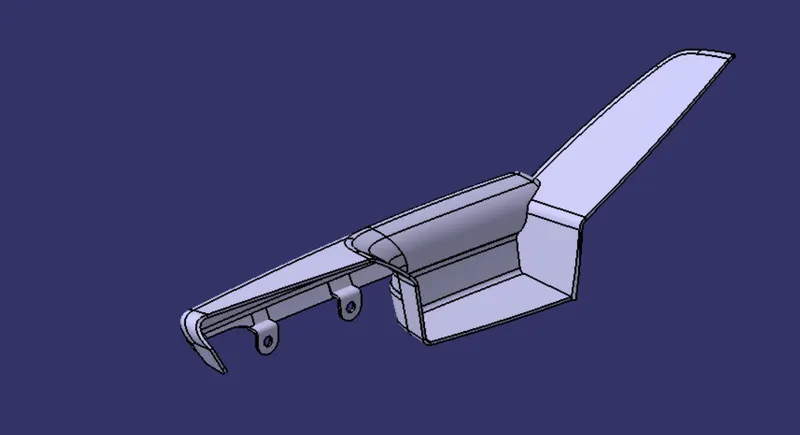
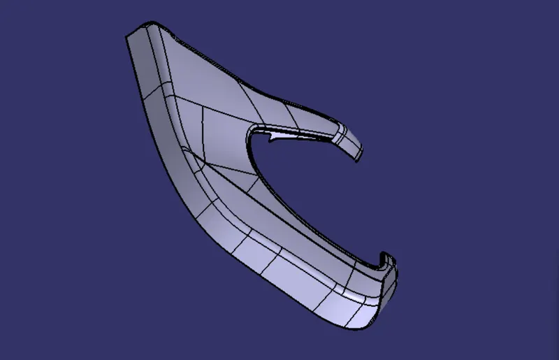
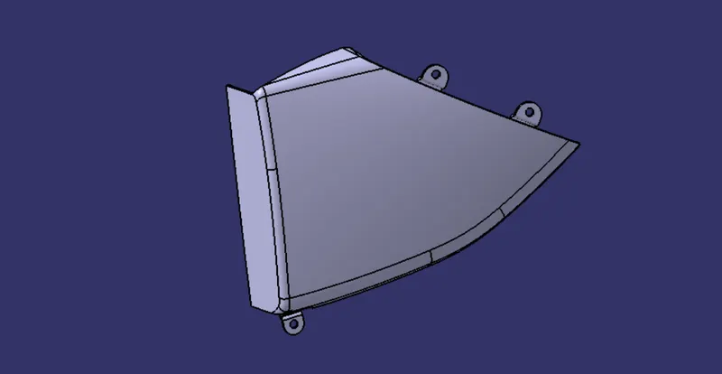
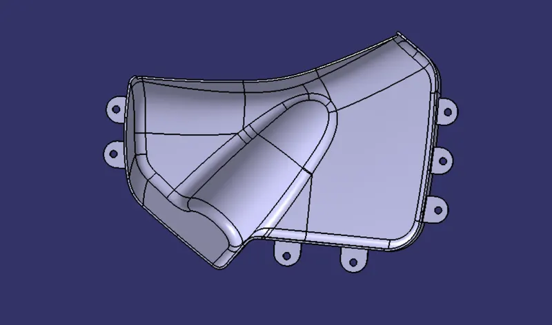
Once the Class A, Class B, and Class C surfaces are created then they are trimmed to form a hollow body, so that we can convert that into a solid body using the closed surface command. In the master section, flanges are given at some places. The flanges will also be created along the solid body.
(i) Arm rest
(ii) Door substrate
(iii) Upper substrate
(iv) Map pocket
Creation of B-side attachments
(i) Dog house
The dog house is an engineering feature used in the plastic trim design to avoid sink marks. Dog houses are used as a supporting feature. Sometimes other engineering features like snaps; locators, etc. are mounded on them to increase their strength.
Here we are using the doghouse to attach the pushpins. We are mounting a total of 4 doghouses. 3 in the door substrate and 1 in the upper substrate.

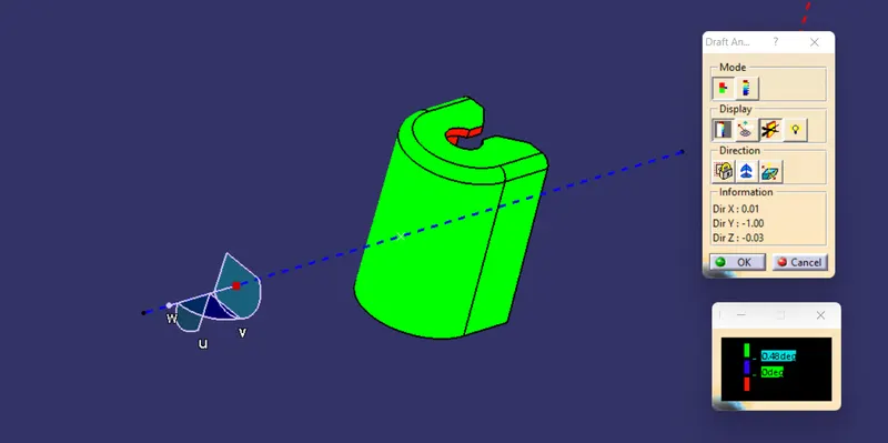
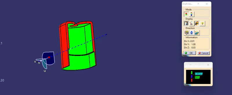
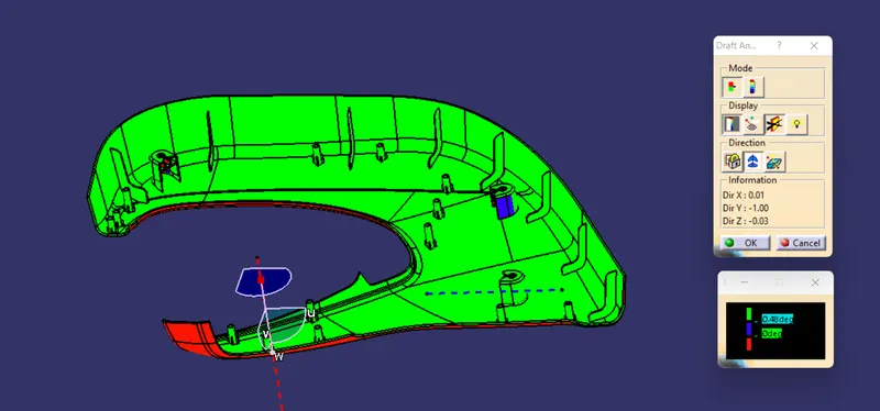
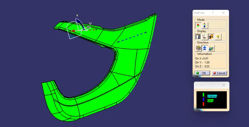
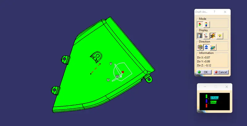
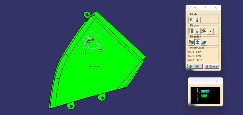
The draft analysis is performed for the dog house. The outer surface will be cleared using the Main tooling axis and the inner surfaces will be cleared using the sliding axis. A draft of 0.5 deg is given in both inner and outer faces.
(ii) Ribs
Ribs are an engineering feature in plastic injection molded parts. They are thin extensions that run perpendicular to a wall or plane. They are commonly used to provide additional support and strength to a part. Thickness and location are essential to rib design. The design rules must be followed while creating the ribs to avoid defects in the component.
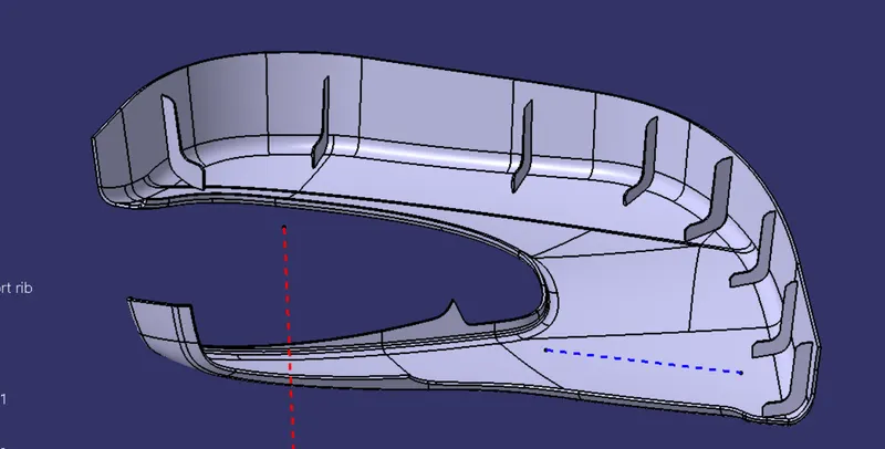
The draft analysis is performed by giving a draft of 0.5 deg to the ribs.
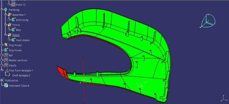
The ribs are getting cleared in the draft analysis.
(iii) Heat stakes
Heat Staking is a pulsed-heat process to join two or more parts out of which one at least is made of plastic. The process is to deform the plastic material using heat and force at a set process time. The bond is made by partially de-forming the plastic part in order to fix each other.
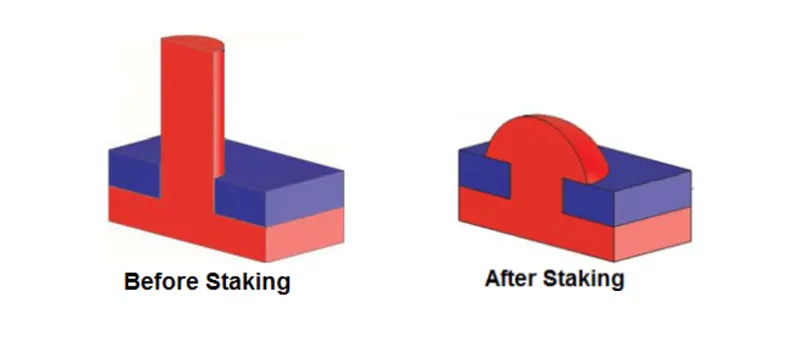
The above image illustrates how the heat staking process is done.
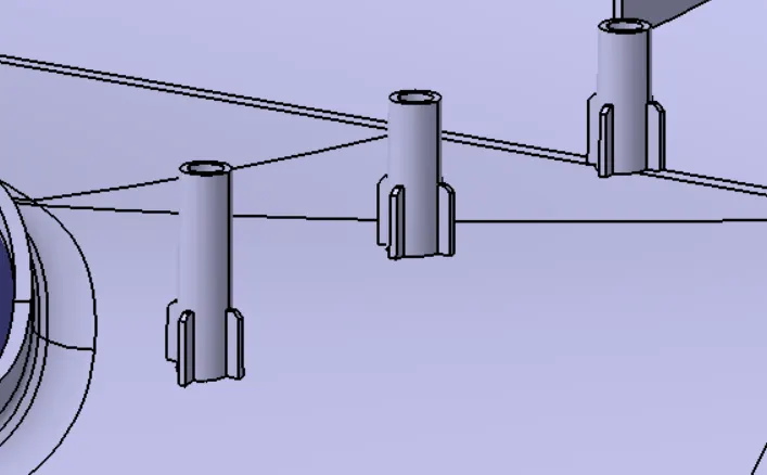
The draft analysis is performed in the heat stakes and the supporting ribs by giving a draft of 0.5 deg.
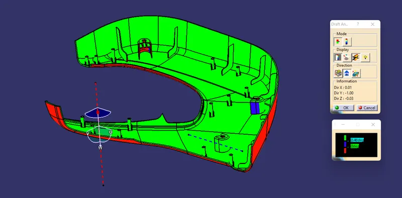
The heat stakes and the supporting ribs are cleared in the draft analysis.
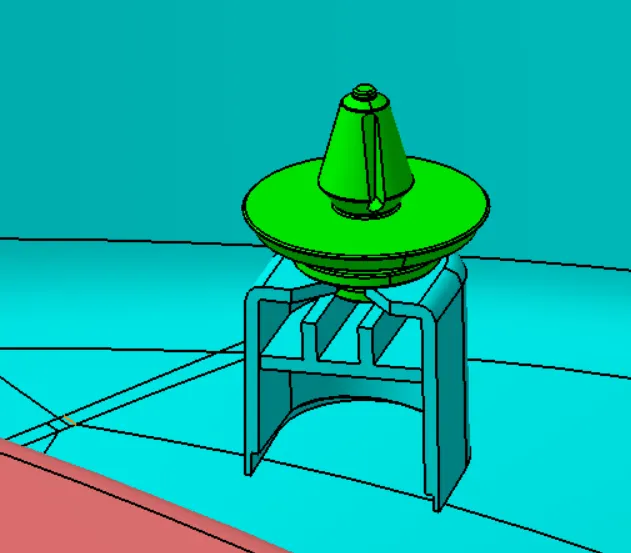
(iv) Push pins
Push pins are used for joining one component to another. These are basically attached to the dog house.
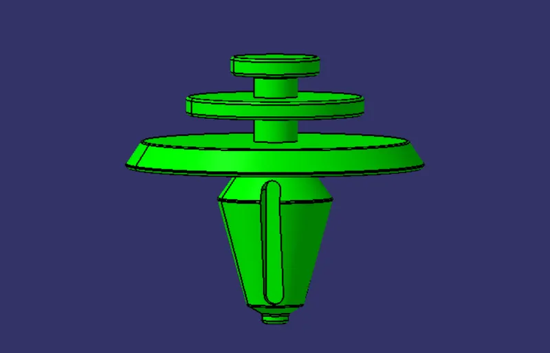
Push pins are attached to the dog house.
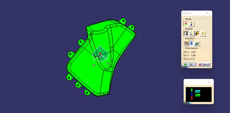
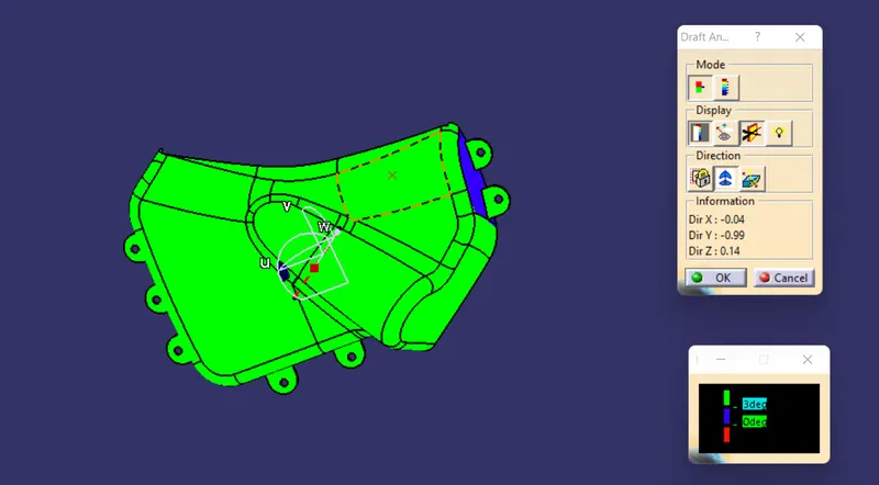
Draft analysis for the final parts
(i) Arm rest
(ii) Door substrate
(iii) Upper substrate
(iv) Map pocket
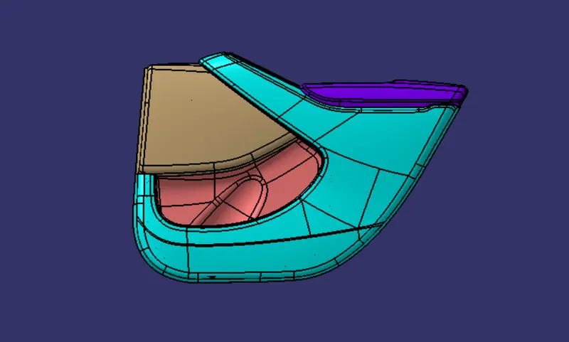
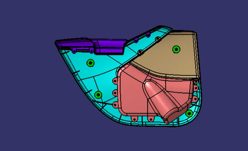
Final view of the door trim
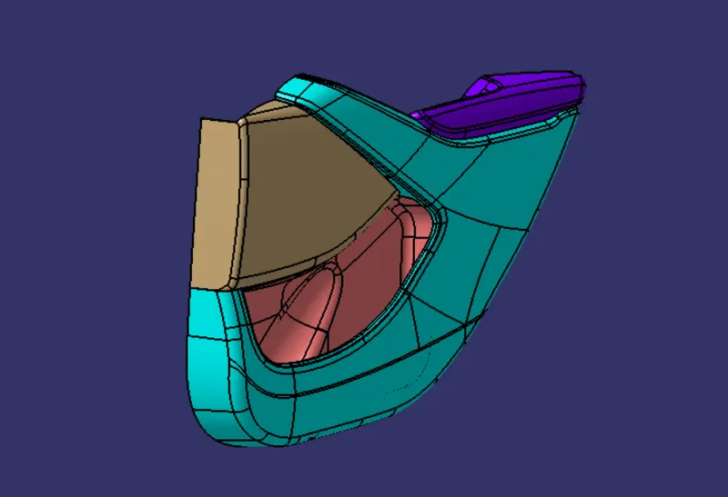
Conclusion
Creation of the car interior door trim is designed using the given class A surface as the input and Class B and C surfaces are created with the help of the Class A surface. By using the given master section, attachment features like Heat stakes, Flanges, Dog houses, and Push Clips are created considering the design rules. The draft analysis has been performed to analyze the draft of the component to check the manufacturing feasibility. A draft of 3 deg (max) and 0.5 deg (min) is applied to all the attachment features. From the above draft analysis results, we can conclude that this component will be ejected easily from the core and will not have defects.