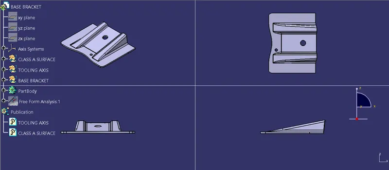
Week 8 - Challenge 2 - Base Bracket Design
In this challange we will be doing draft analysis on BASE BRACKET using CATIA V5
DRAFT ANANLYSIS
Draft ananlysis is a method used in design to check whether the component created in CAD is manufactrable based on the draft condition applied. The main reason behind draft ananlysis is the part manufacted should easily removed from the mold. It also gives an idea of draft angle from the tooling direction. here we are giving a tooling direction inorder to eject the component easily from the tool. The ideal draft angle given in automotive industries for plastic components are 3 degree.
Some of the components where draft analysis is done are hood, fenders, roof, side doors etc.
PROCEDURE FOR PERFORMING DRAFT ANALYSIS
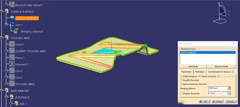
1. Ensuring no gap in the model
Once the class A surface is recieved, the designer has to check whether the surface is closed. This can be checked by using the join or boundary option.
2. Creation of tooling axis
Tooling axis plays an important role in manufacturing of plastic products. The axis decides in which direction the mould will work while production of the component.
The main focus while deciding the tooling axis is the clearing the component in the moulding in the same axis with the minimum use of side core for producing the component.
For particular component X,Y & Z can be the possible tooling axis.
In this component, Z direction will be the axis where most of the parts are cleared. Therefore, we choose Z direction for tooling.
To check clearance in YZ plane
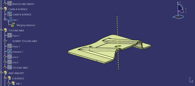
Intersect the YZ plane in the axis system with the classA surface to obtain the intersect sketch which needs to cleared in the ZX plane. After getting the intersect try to analyse the dummy direction of tooling axis and the sketch which is perpendicular to dummy tooling axis.It will be cleared in the tooling direction easily. For the inclined line at an angle to the dummy tooling axis we need to find the ZX tooling axis for that sketch of the component in yz plane.
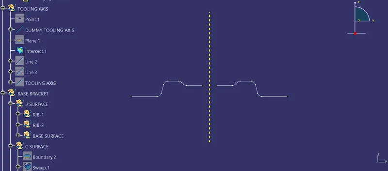
As you can see the inclined sketch is symmetrical to the dummy axis. All you need is to extend the inclined line and and bisect it with the point to obtain thee tooling axis in the YZ plane. The yellow colour line is the tooling axis in YZ plane.
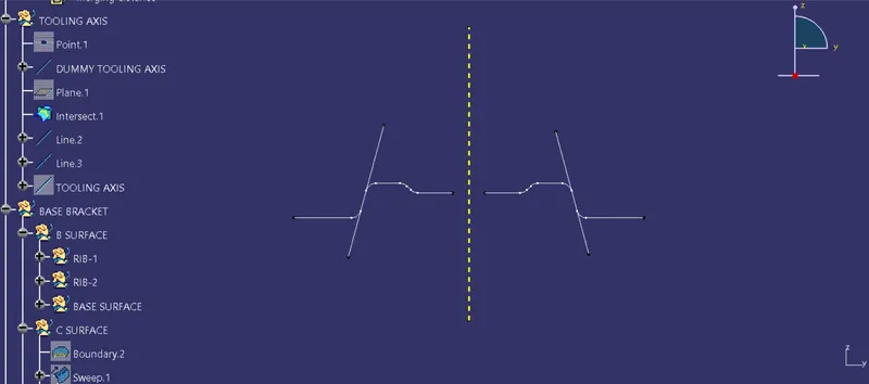
Now, bisecting both the line we get a new line which is our main Tooling axis.
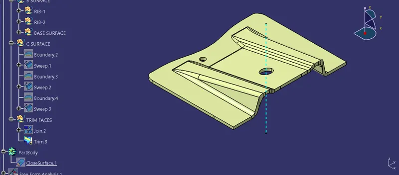
3. CREATING PUBLICATION
After the creation of the tooling axis we can insert the publication from the insert tool, the publication serves your time while working on the class A for the draft analysis as well as thickening of the component you can directly select your tooling axis and class A SURFACE as and when required during working on the class A surface.
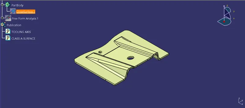
4. DRAFT ANALYSIS
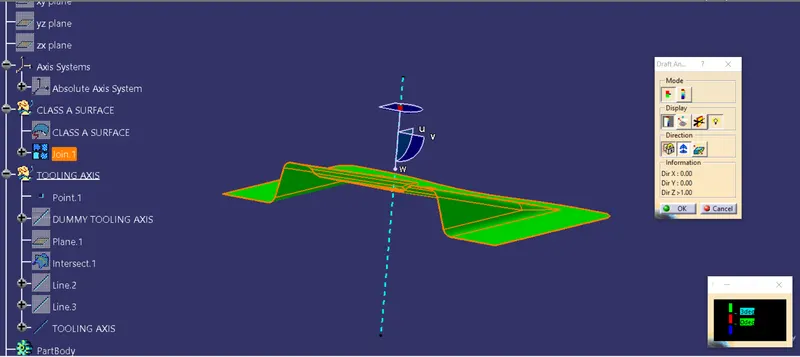
The draft analysis is an important tool as it helps the user to analyse the draft at various surfaces, the draft analyser in catia uses the colour codes for the identifiction of the draft. Each colour has its own meaning for minimum draft negative draft and under draft.
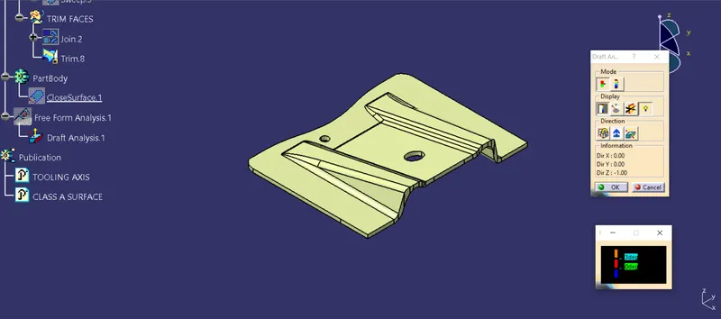
The draft analyis toolbar provide two modes for analysis the draft, first is the quick analyis which basically has three colours for analyzing GREEN RED,AND BLUE on the other hand other option is the full analyis mode which enables few more detailing into the draft and is used in the complex comporlents like instrument panel etc. In above challenge we have used the quick analysis mode for analysing draft here. Now, bring the compass and align it with the tooling axis and click the lock button in the dialog box.
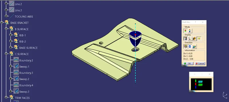
After setting the compass along the tooling axis direction take the cursor on to the class A surface to analyze the surface, if the surface turns out be green fully it indicates draft value given is achieved throughout, we have given draft limit as 3 degrees minimum which is shown in colour code box (green colour).
Solid part in differnt views
Isometric view
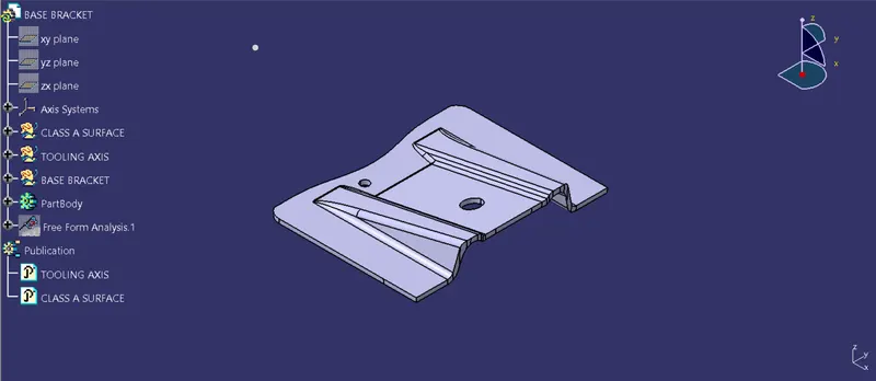
Front view
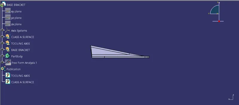
Side view
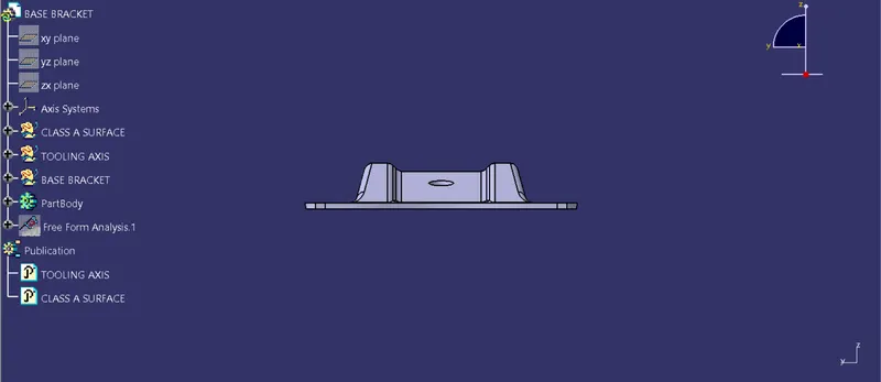
Top view
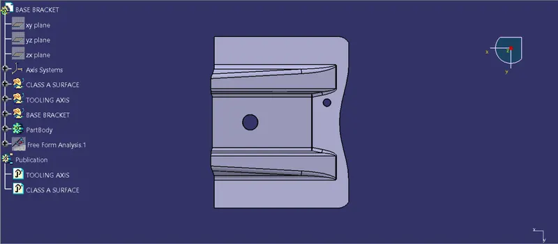
Multi view