Week 8 - Challenge 4 - Coin Holder Design
In this challenge we will be doing draft analysis on COIN HOLDER using CATIA V5.
DRAFT ANALYSIS
Draft analysis is a method used in design to check whether the component created in CAD is manufacturable based on the draft condition applied. The main reason behind the draft analysis is the part manufactured should be easily removed from the mold. It also gives an idea of the draft angle from the tooling direction. Here we are giving a tooling direction in order to eject the component easily from the tool. The ideal draft angle given in automotive industries for plastic components is 3 degrees.
Some of the components where draft analysis is done are hood, fenders, roof, side doors, etc.
PROCEDURE FOR PERFORMING DRAFT ANALYSIS
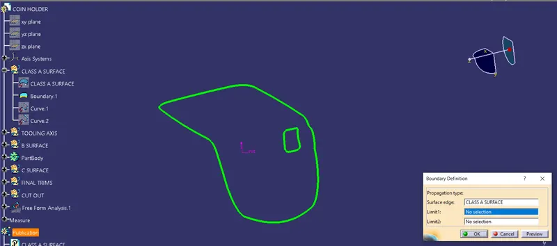
1. Ensuring no gap in the model
Once the class A surface is received, the designer has to check whether the surface is closed. This can be checked by using the join or boundary option.
2. Creation of tooling axis
For this component, we can create the tooling axis by taking the bottom surface as a reference. Then we can create a line using the point-Direction option. Create a point on the center of the bottom surface. Now, we can create a line by selecting the point and direction as the surface.
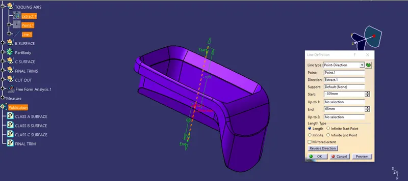
This line will be considered as our tooling axis.
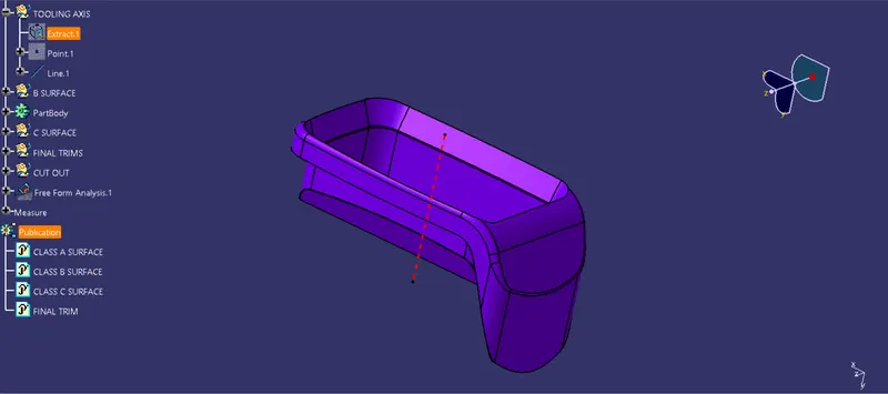
3. CREATING B SURFACE
To make the B surface, the surfaces of class A are extracted to a given thickness (2.5mm given). Then, the surfaces are untrimmed individually. After this using the TRIM option, the surfaces are trimmed to get the required shape.
Once we get the desired surface, apply the edge fillet.
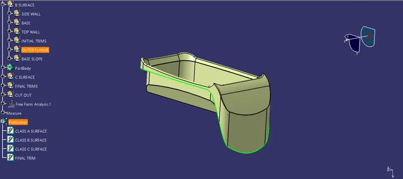
4. CREATING C SURFACE
For creating C surface, we use the boundary of Class A surface and use the sweep option and give the draft value of 3 deg.
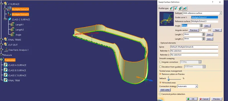
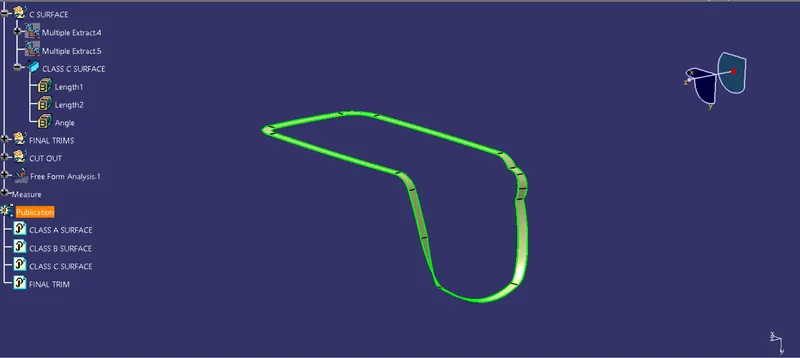
5. MAKING THE SURFACE INTO SOLID
Once the B surface and C surface are created, the Class A surface is trimmed with the Class C surface. The output is again trimmed with Class B surface. Now, we have got the desired part on the surface. Change the workbench into the Part design and using the closed surface option make the final output a solid part.
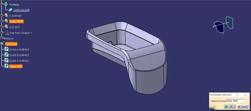
6. CREATING PUBLICATION
After the creation of the tooling axis, we can insert the publication from the insert tool, the publication saves your time while working on class A for the draft analysis as well as thickening of the component you can directly select your tooling axis and class-A surface as and when required during working on the class A surface. We can also add Class B and C surfaces to publications.
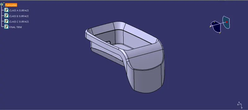
7. DRAFT ANALYSIS
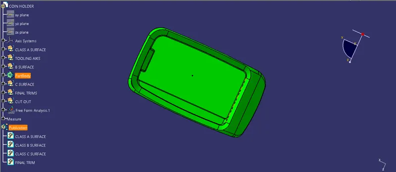
The draft analysis is an important tool as it helps the user to analyze the draft on various surfaces, the draft analysis in CATIA uses the color codes for the identification of the draft. Each color has its own meaning for the minimum draft negative draft and under draft.
The draft analysis toolbar provides two modes for analysis of the draft, first is the quick analysis which basically has three colors for analyzing GREEN, RED, AND BLUE on the other hand other option is the full analysis mode which enables a few more details into the draft and is used in the complex components like the instrument panel, etc. In the above challenge, we have used the quick analysis mode for analyzing the draft here. Now, bring the compass and align it with the tooling axis and click the lock button in the dialog box.
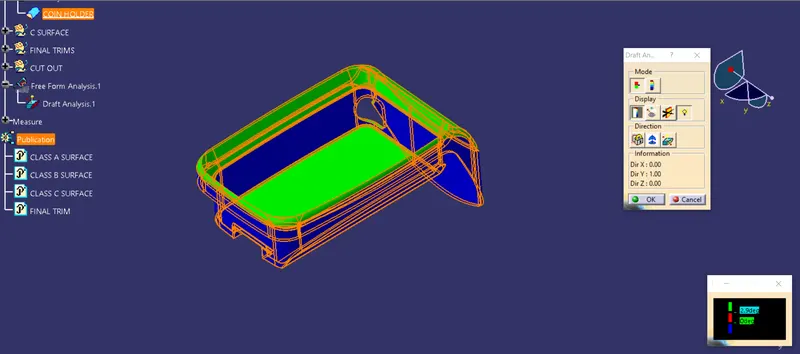
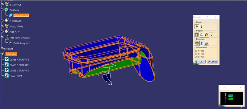
Since we have not given the draft angle for the Class C surface it has not been cleared in the draft analysis.
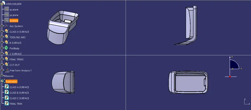
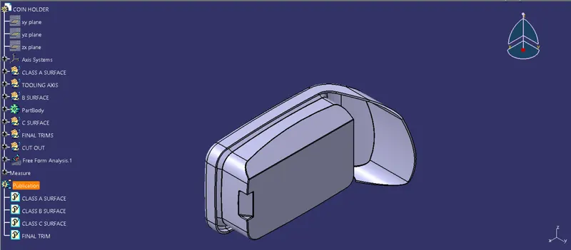
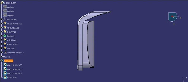
COIN HOLDER IN DIFFERENT VIEWS
Isometric view
Front view
Side view
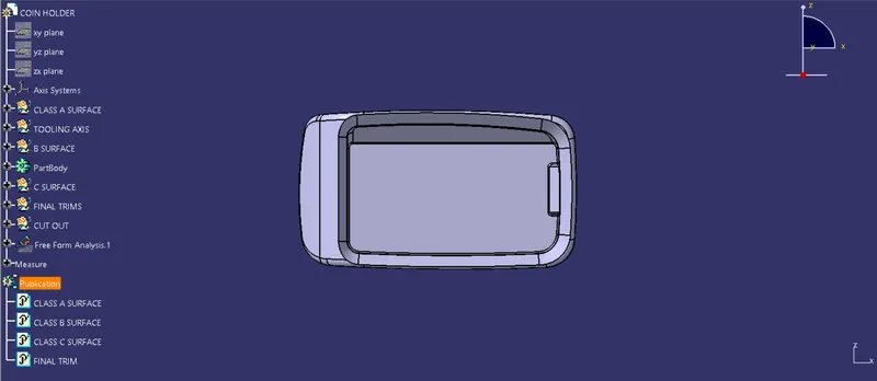
Top veiw
Multi view