Week 9 - Project - Master Section Development
MASTER SECTION DEVELOPMENT OF B-PILLAR
Aim:
To create the Class B and Class C surfaces for the given Class A surface, develop the B-Side features given in the Master section, and perform Draft analysis.
B-Pillar:
The vertical roof support structure is located between the front and rear doors of a car. It corresponds with the A-pillar situated on either side of the windshield at the front of the car and the C pillar which sits on either side of the rear window on a typical sedan.
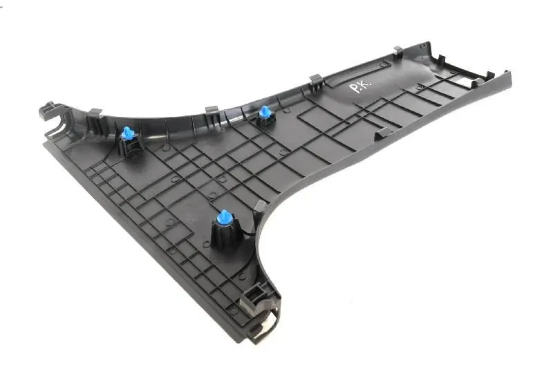
Usually, the B-Pillar trim is manufactured using injection molding. While modeling we have to consider the design rules so that it is manufacturable.
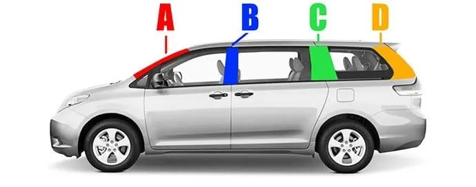
DESIGN METHODOLOGY FOLLOWED
- Creation of Tooling axis
- Creation of Class B
- Creation of Class C
- Creation of closed volume
- Creation of Dog house
- Creation of 4 Way locators
- Creation of Ribs
- Performing Draft analysis
CREATION OF TOOLING AXIS
The Tooling Direction is basically the direction that the mold pulls apart. The mold is built in two separate pieces, basically. You have a Cavity side and you have the Core side. The Core pulls apart from the Cavity along the Tooling axis.
The tooling axis can be created in many ways. It's the choice of the designer. But it should be in a way that most of the surface get cleared using the Tooling axis.
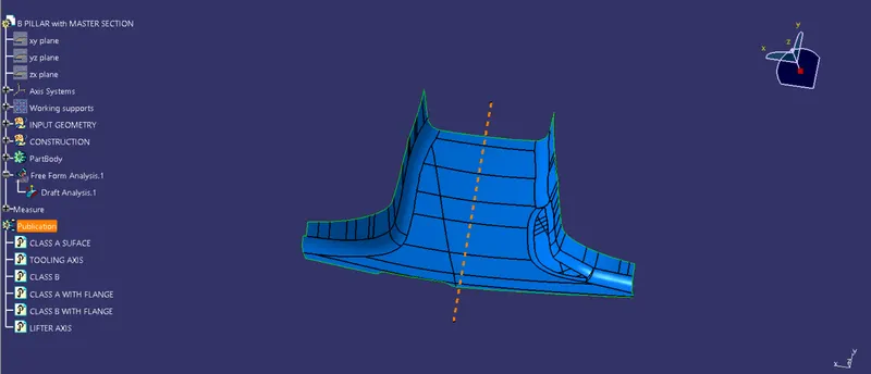
In this case, I've created the tooling axis using the normal to surface method.
CREATION OF CLASS B SURFACE
The Class B surface is the inner surface which will have all engineering features and attachments in it. It is created with the reference of the Class A surface.
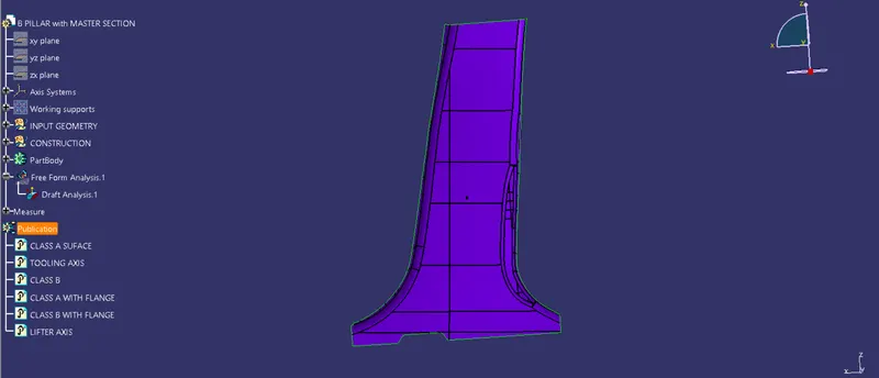
In the master section provided, it has a flange around the edges. So, we have to create that flange also.
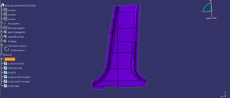
The flange is created with the reference of the Master section.
CREATION OF CLASS C SURFACE
The Class C surface is the connecting surface between the Class A and Class B surfaces. In most cases, Class C is created using the sweep option. Once creating the C surface, it is trimmed with Class A and B surfaces to form a closed body. Then, it is made into a solid part.
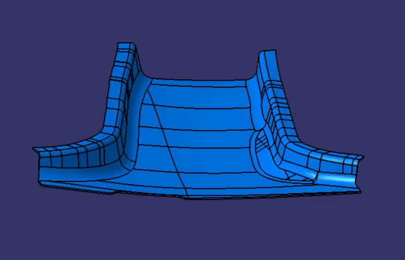
For clear understanding, we can take a cross-section of the final trimmed surface.
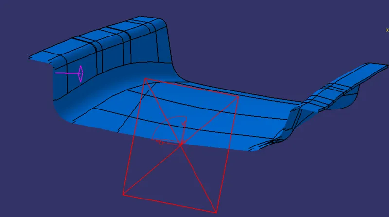
Hence, the final trim is done with Class A and B surfaces. From this, we can create a solid part.
CREATION OF CLOSED VOLUME
Once the final trim is done we can change the workbench to Part design and create a closed volume using the Closed surface option.
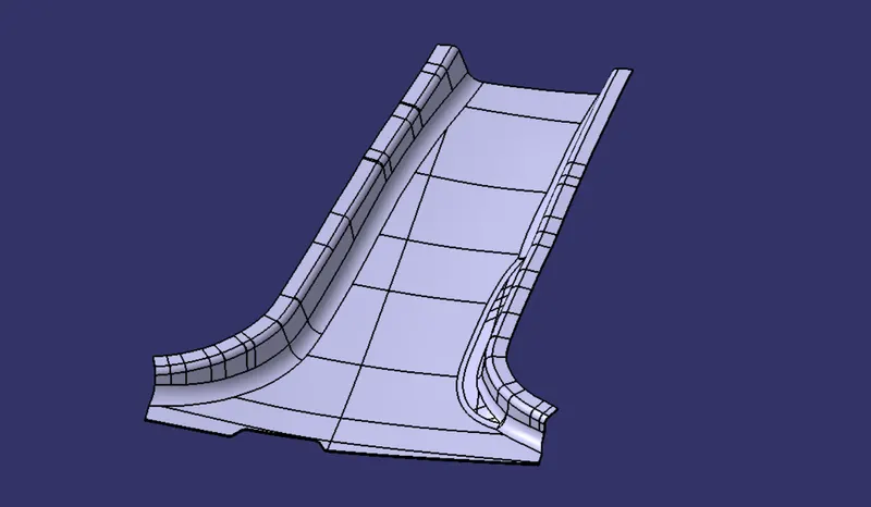
The above image shows the solid part made using the Closed surface.
CREATION OF DOG HOUSE
A Dog house is an engineering feature used in the plastic trim design. Dog houses are used as a supporting feature. Sometimes other engineering features like snaps, locators, etc. are mounded on them to increase their strength. Dog houses are also used to avoid sink marks in plastic components.
A sketch is made with the reference from the master section provided to create the Dog house. In the master section, there is an undercut given to the dog house which has to be created.
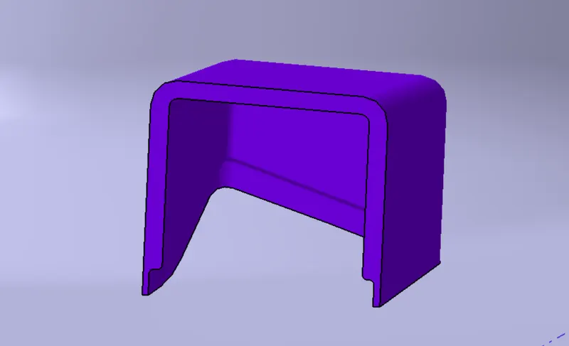
In the master section, there is two dog house on each side. To create the other dog house we can use the symmetry option. A reference plane is created between the two dog houses and it is copy-paste using the symmetry option.
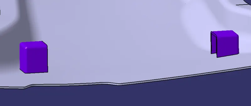
Hence, the Dog houses are created considering the design rules.
CREATION OF 4-WAY LOCATOR
A 4-Way locator is a round locating pin located concentrically in a hole which helps to locate a workpiece on a fixture or to align two pieces of a fixture. The main use of a locator pin is to arrest the maximum degrees of freedom.
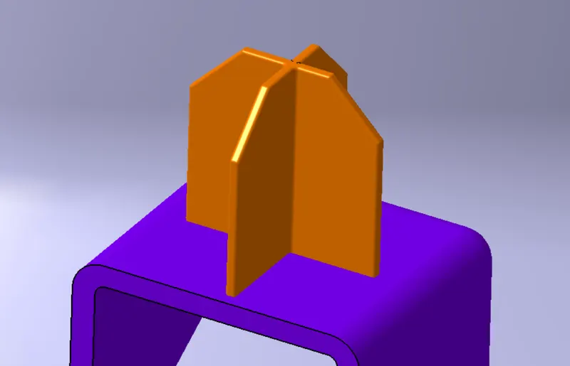
Hence, the 4-Way locator is created considering the design rules.
CREATION OF RIB
Ribs are a feature of plastic parts. They are thin extensions that run perpendicular to a wall or plane. They are commonly used to provide additional support and strength to a part.
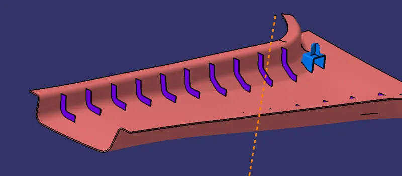
The ribs must be created on both sides 50mm each apart.
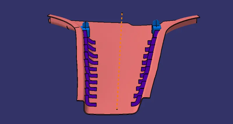
Hence, the ribs are created considering the design rules.
PERFORMING DRAFT ANALYSIS ON B-PILLAR
The Draft AnalysiS is used to detect if the part you drafted will be easily removed. This type of analysis is performed based on color ranges identifying zones on the analyzed element where the deviation from the draft direction at any point, corresponds to specified values.
Advantages of Draft Analysis
- Reduces the chance of damage to the part due to friction during the release
- Reduces wear and tear and chances of damage to the mold
- Ensures a uniform, smooth, unscratched finish when required
- Ensures the integrity and uniformity of other surface finishes and textures
- Reduces overall cooling time by lessening or eliminating the need for unconventional ejection setups
Draft analysis on B-Pillar
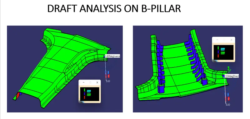
Colour representation in the draft analysis
Green - Draft angle is 3 deg or more than 3 deg
Blue - Draft angle is between 0 to 3 deg
Red - Negative draft
From the above image we can observe that in some areas, the draft is less than 3 deg. As it is a very small surface we can ignore it.
Draft analysis on Dog house
For the Dog house, we will have a separate tooling axis called the Lifter axis. The dog house will be cleared using the Lifter axis and the outside walls will be cleared in the Main tooling axis. A draft of 0.5 deg is given to all the faces in the Dog house.
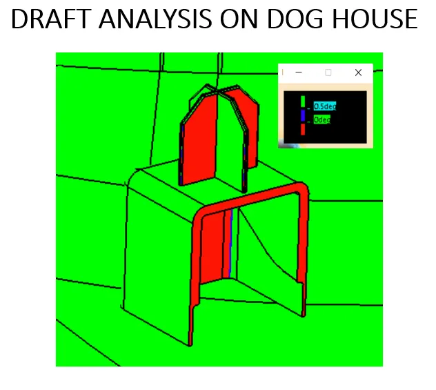
Most of the faces have been cleared. Except for the side face shown in the figure. Where the Draft is negative.
Draft analysis on Ribs
The Draft analysis is performed using the Main Tooling Axis.
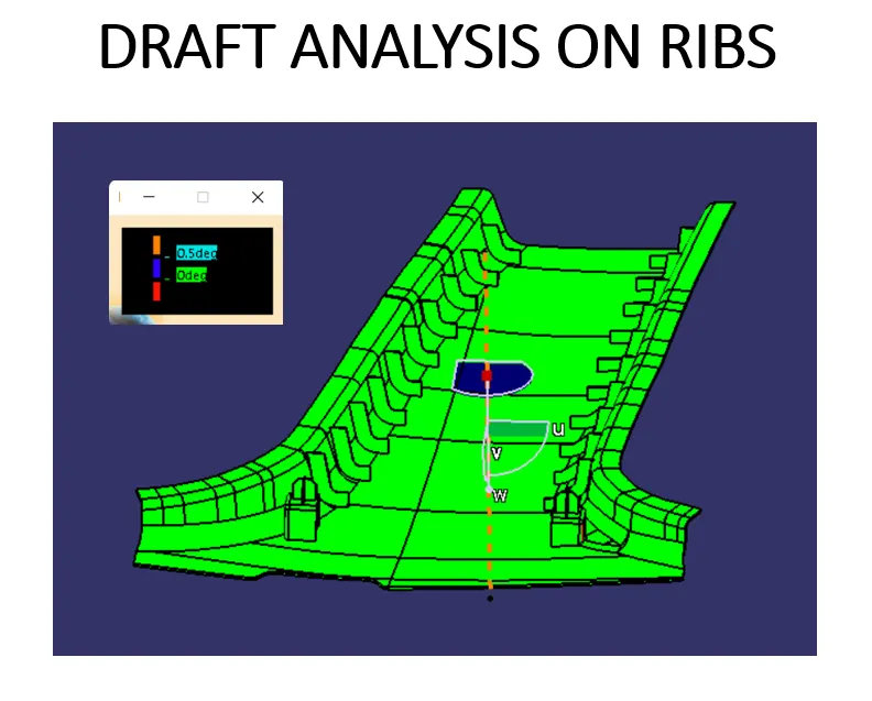
From the above image, we can see that the Ribs are cleared using the Main tooling axis. Tha Draft value given is 0.5 deg.
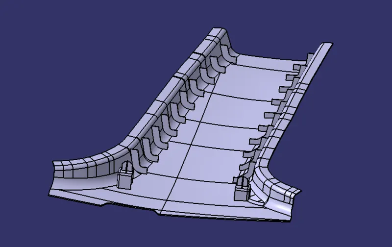
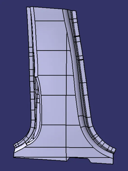
Final solid part model
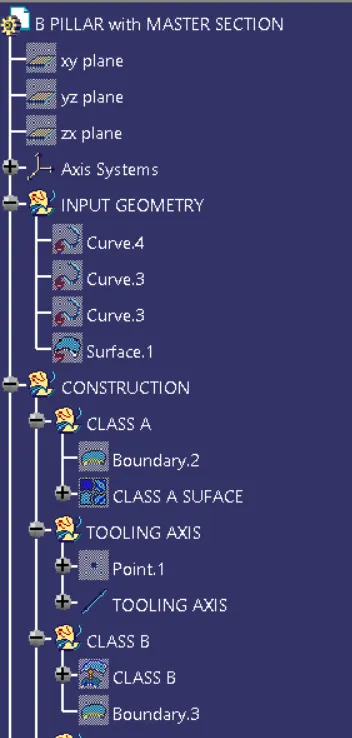
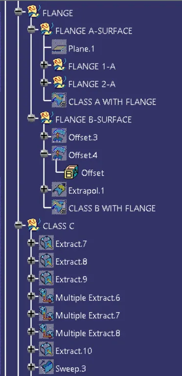
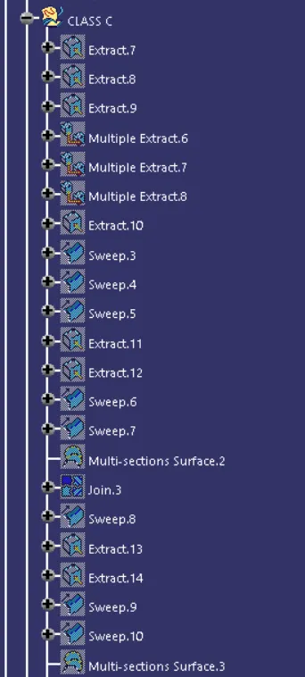
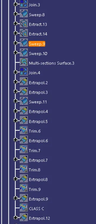
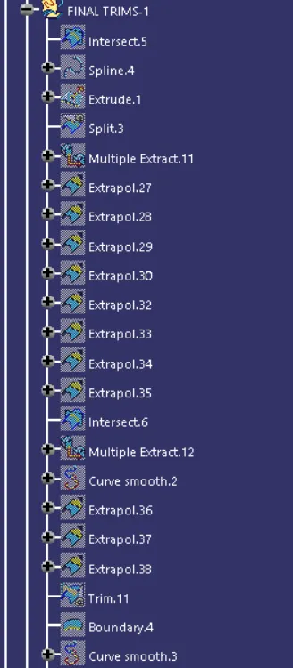
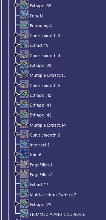
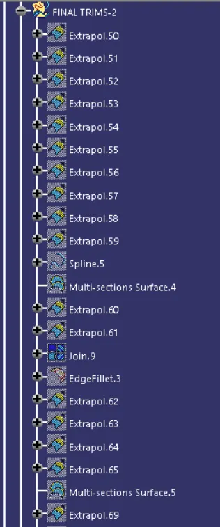
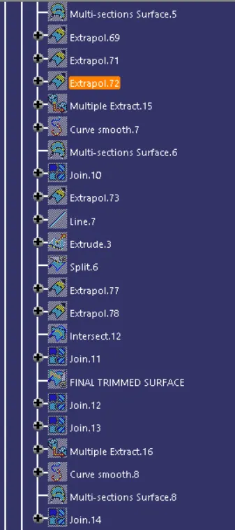
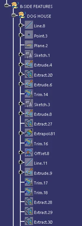
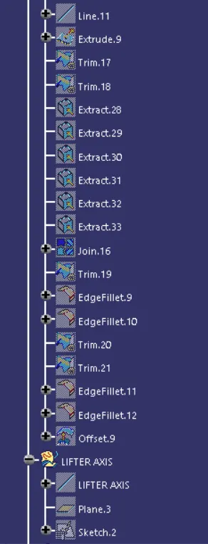
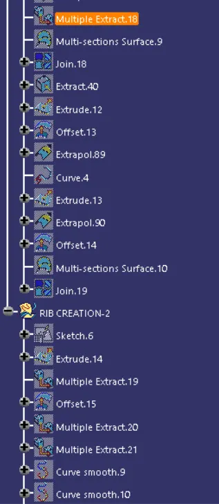
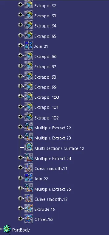
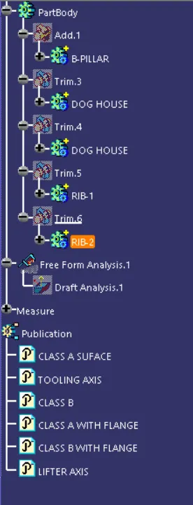
Feature Tree Structure
***END ***