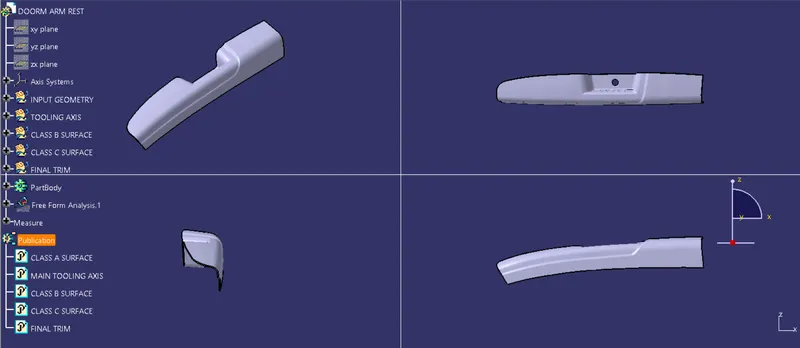
Door Arm Rest Week 8 Challenge
In this challange we will be performing draft analysis on DOOR ARM REST using CATIA V5.
DRAFT ANALYSIS
Draft analysis is a method used in design to check whether the component created in CAD is manufactrable based on the draft condition applied. The main reason behind draft ananlysis is the part manufacted should easily removed from the mold. It also gives an idea of draft angle from the tooling direction. Here we are giving a tooling direction inorder to eject the component easily from the tool. The ideal draft angle given in automotive industries for plastic components are 3 degree.
Some of the components where draft analysis is done are hood, fenders, roof, side doors etc.
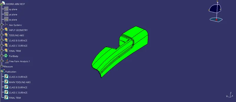
PROCEDURE FOR PERFORMING DRAFT ANALYSIS
1. Ensuring no gap in the model
Once the class A surface is recieved, the designer has to check whether the surface is closed. This can be checked by using the join or boundary option.
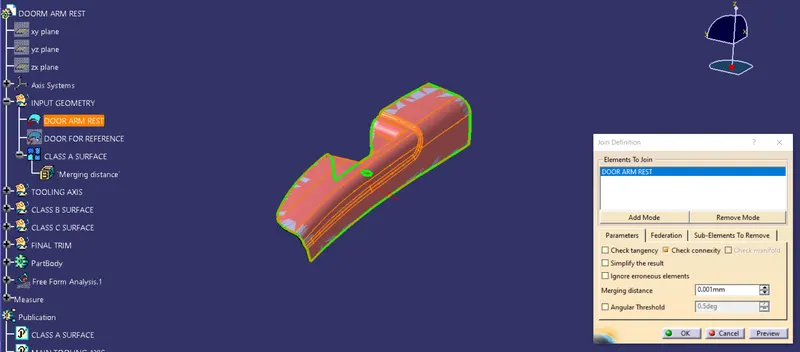
2. Creation of tooling axis
Tooling axis plays an important role in manufacturing of plastic products. This axis decides in which direction the mould will work while production of the component.
The main focus while deciding the tooling axis is the clearing the component in the moulding in the same axis with the minimum use of side core for producing the component.
For particular component X,Y & Z can be the possible tooling axis.
In this component, Z direction will be the axis where most of the parts are cleared. Therefore, we choose Z direction for tooling.
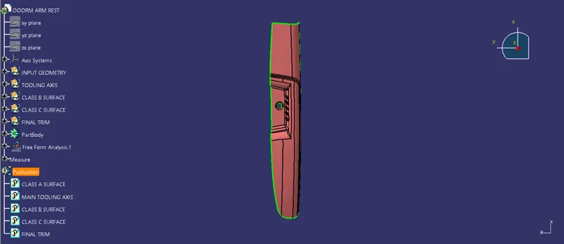
Creating the dummy tooling axis
The Center of Gravity is found using the inertia option available in Catia V5. Once the CG is found a line is drawn using the point-direction option. The CG is selected as the point and Z axis is selected as direction. This line will be considered as Dummy tooling axis.
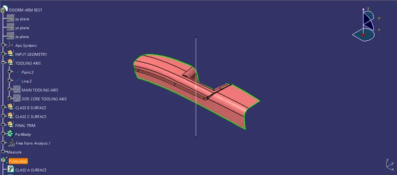
Performing trail Draft analysis
Now, a trail Draft analysis is performed to find the main tooling direction. Here trail and error by compass method is used. The compass is placed in the dummy tooling axis and draft analysis is performed. If the component is cleared, then the dummy tooling will be considered as Main tooling axis.
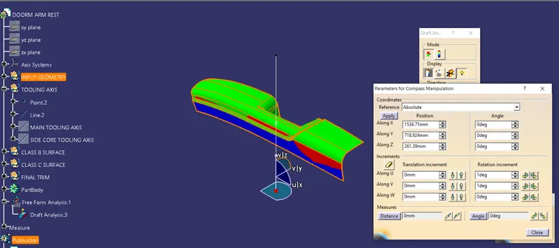
If not cleared, then the compass is moved by 1 deg in X and Y direction. Then again draft analysis is performed. The same trail and error is performed untill the component is cleared.
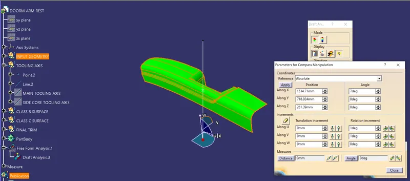
When the rotation angle is increased by 1 deg in X and Y diection, the component is cleared. But a surface is not cleared which can be cleared using side core. So, a new tooling axis should be created for side core.
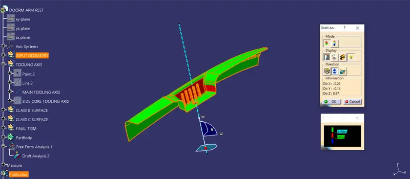
Then the compass is locked and exit from draft analysis. A line is created using point-direction option. The point is selected as CG and the direction is selected as the compass direction. And the compass is released from lock. The line created will be our Main tooling diection.
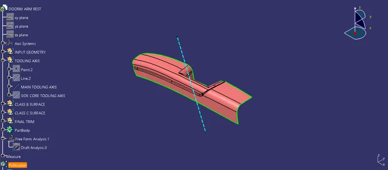
Hence, the Main Tooloing axis is found using the Trail and error by compass method.
Creating the tooling axis for side core
The same method used for creating the main tooling axis is used here. But, in side core tooling axis Y axis is used as direction instead of Z axis. The component is cleared at first trail itself. So, we can directly assume that line as side core tooling axis.
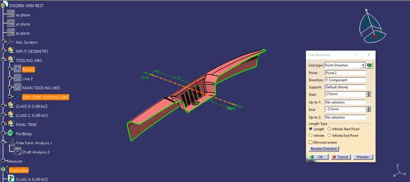
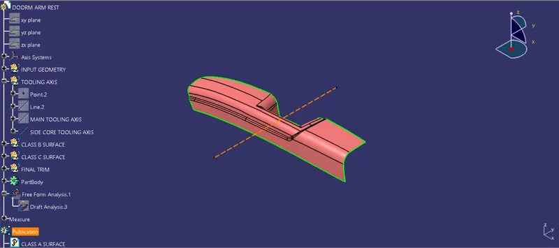
Hence, the side core tooling axis also created.
3. CREATING CLASS B SURFACE
To make the B surface, the surfaces of class A are extracted and offsetted to given thickness (2.5mm). Then, the surfaces are untrimed induvidually. After this using TRIM option, the surfaces are trimed to get required shape.
Once we get the desired surface, edge fillet is applied.
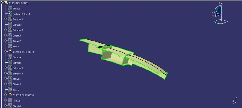
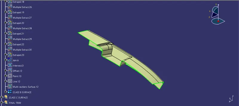
Hence, we have created the Class B surface.
4. CREATING CLASS C SURFACE
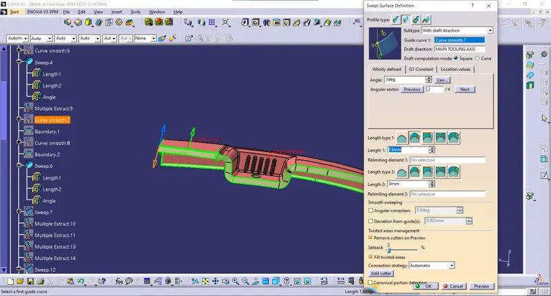
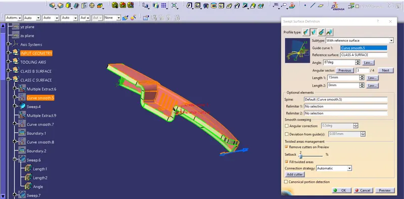
The bounday of Class A surface is extracted and using sweep with draft direction option the main tooling axis is selected and extacted boundary is selected as guide curve. For horizontal surfaces give the angle as 3 deg and for vertical surfaces give the angle as 87 deg. Ensure that the arrow is pointing towards outside direction.
For complex surface where sweep is not working we can use Multi-Section surface. Select the two end surfaces as section and the boundary of the surface to be created as guide curve. Make sure that the two arrow are in the same direction, if not change the direction.
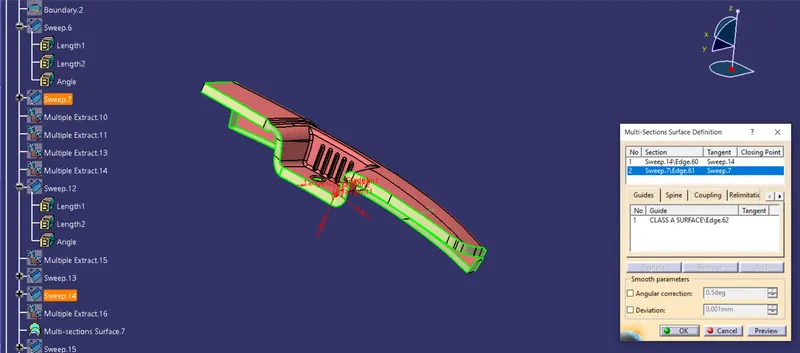
Make sure that there is no gap inbetween the surfaces. If found any gaps, extrapolate the surfaces and trim the extra surfaces.
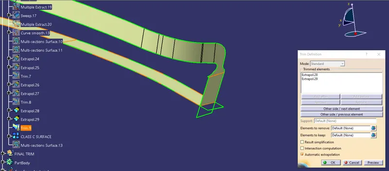
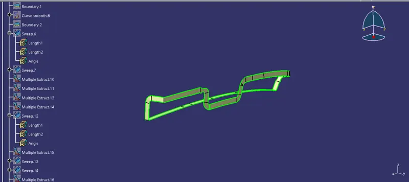
Hence, the Class C surface is created.
5. MAKING THE SURFACE INTO SOLID
Once the B surface and C surface are created, the Class A surface is trimed with the Class C surface. The output obtained is again trimed with Class B surface to get the required surface.
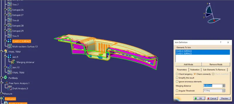
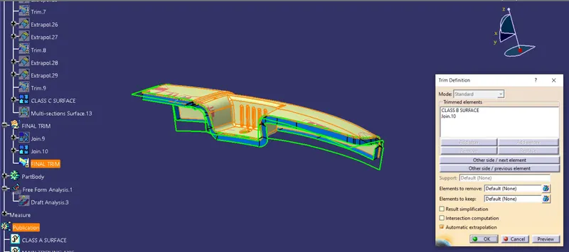
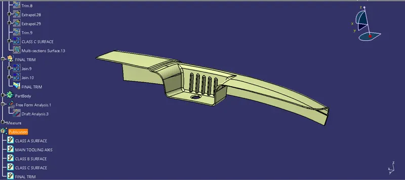
Hence, the final required surface is created. Now, we can make this surface into solid part. Change the workbench into Part design and using closed surface option make the final output as a solid part.
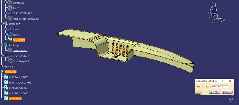
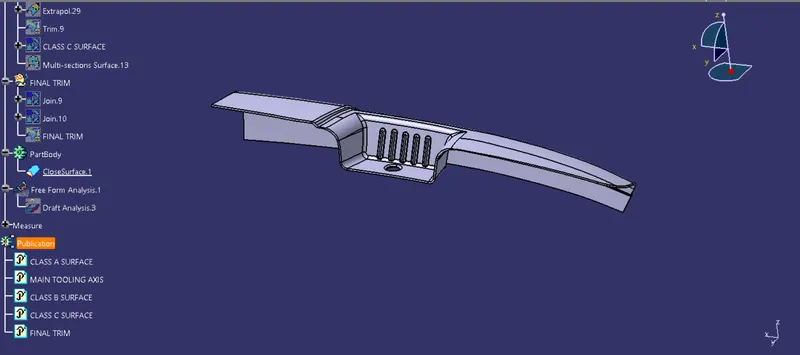
Hence, we have got the desired output.
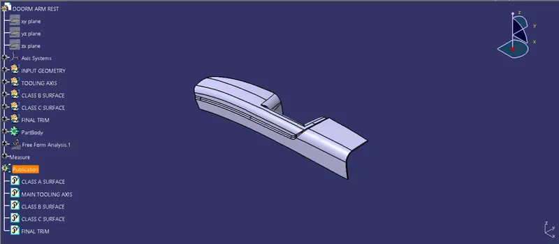
6. CREATING PUBLICATION
After the creation of the tooling axis we can insert the publication from the insert tool, the publication saves your time while working on the class A for the draft analysis as well as thickening of the component you can directly select your tooling axis and required class surfaces and when required during working on the class A surface.
7. DRAFT ANALYSIS USING MAIN TOOLING AXIS
The draft analysis is an important tool as it helps the user to analyse the draft at various surfaces, the draft analyser in catia uses the colour codes for the identifiction of the draft. Each colour has its own meaning for minimum draft negative draft and under draft.
The draft analyis toolbar provide two modes for analysis the draft, first is the quick analyis which basically has three colours for analyzing GREEN RED,AND BLUE on the other hand other option is the full analyis mode which enables few more detailing into the draft and is used in the complex components like instrument panel etc. In this challenge we will use the quick analysis mode for analysing draft here. Now, bring the compass and align it with the tooling axis and click the lock button in the dialog box and select the part.
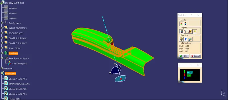
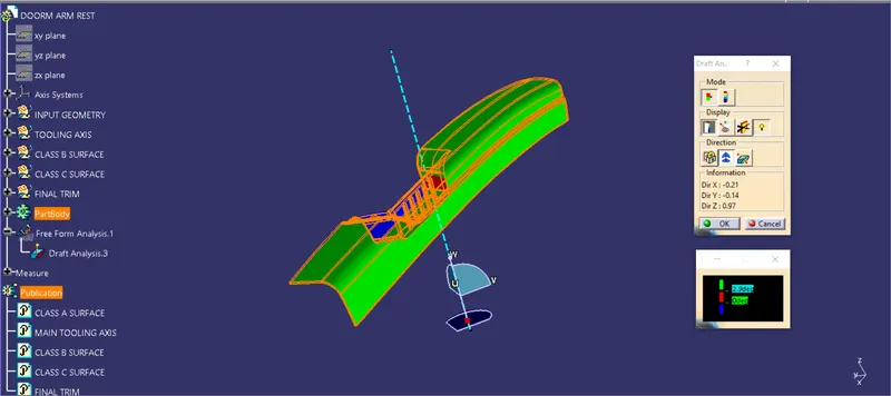
Most of the surfaces are cleared using main tooling axis except the side surface. That can be cleared using side core tooling axis.
8. DRAFT ANALYSIS USING SIDE CORE TOOLING AXIS
The same procedure, followed in Main tooling will be followed here. But in this case the tooling axis will be side core tooling axis.
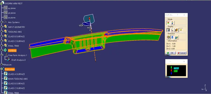
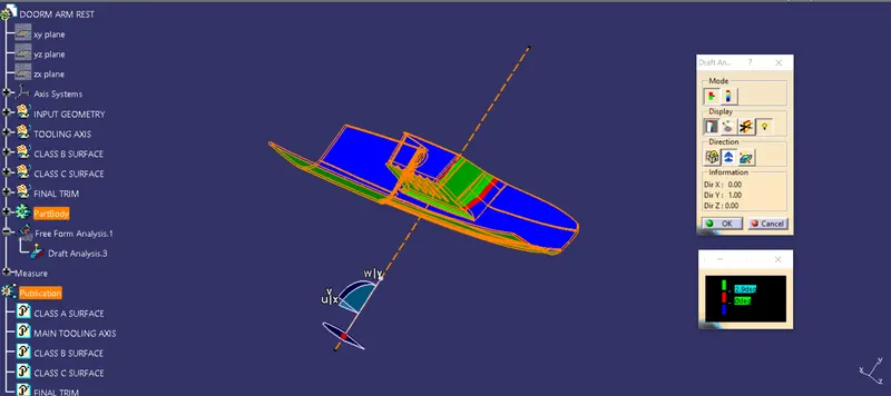
By using the side core tooling axis, the surfaces which were not cleared in the main tooling axis has been cleared here.
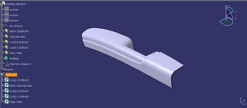
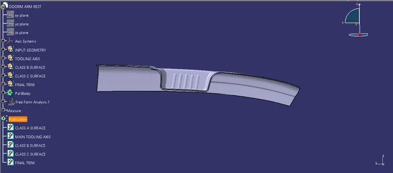
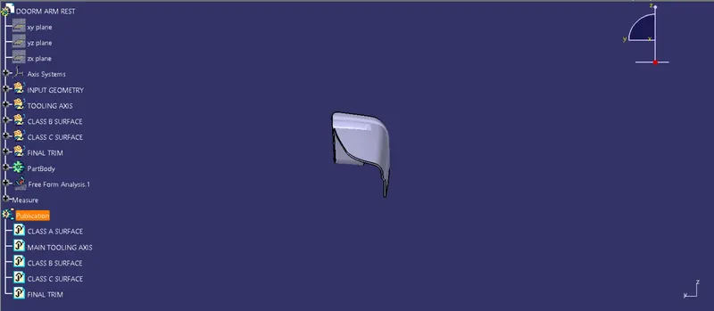
Door arm rest in different views
Isometric view
Front view
Side view
Top view
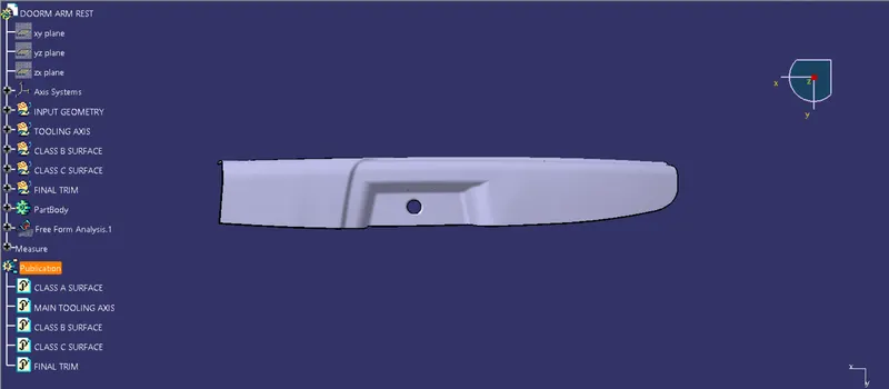
Multi veiw