DESIGN, ASSEMBLY AND RENDERING OF SUNSEEKER PREDATOR YATCH
DESIGN, ASSEMBLY, AND RENDERING OF SUNSEEKER PREDATOR YATCH
Objective
- To design the parts of Sunseeker predator Yatch and assemble them using SOLIDWORKS software.
- To set proper image quality and getting realistic view with the help of photoview 360.
Introduction
A yacht is a type of boats or power vessel used for pleasure, cruising, or racing. The term applies to such vessels that have a cabin with amenities that accommodate peoples to stay. To be termed a yacht, as opposed to a boat, such a pleasure vessel is likely to be at least 33 feet (10 m) in length and may have been judged to have good aesthetic qualities. While sailing yachts continued to exist, the development of reliable power plants created a new category of pleasure craft. The power plants started with the stream engine and transitioned to the internal combustion engine. Whereas sailing yachts continued to be steered from the after portion of the vessel, power yachts adopted the bridge in a forward cabin structure that afforded better forward and sideways visibility.
The following components which were designed are
- Propeller
- Radar
- Hull
- Garage door
- Superstructure
- Front, Middle and Rear seats
- Radarmast
Design approach
There are two types of approach in design procedure.
- Bottom-up approach
- Top-down approach
Here in this project, we have used Bottom-up approach, we get a clear idea by defining these terms.
- Bottom-up approach: The design approach in which the most primary operations are specified first then combined it later to make larger progressive unit and mate relations are given to fix the components.
- Top-down approach: Top-down assembly modelling is an assembly-centric modelling method where the assembly design is started at the highest level possible, and individual parts and subassemblies are defined within the context of the overall assembly.
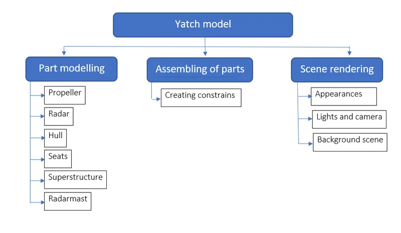
Design process
The entire modelling process is divided into six stages:
- Blueprint setup and modelling of Propeller and Radar
- Modelling of Hull and Garage door
- Modelling of Superstructure
- Modelling of Radarmast
- Modelling of Front, Middle and Rear seats
- Assembling of Yatch
Let’s see what are the features and commands used in the entire model to design different parts:
- Line
- Circle
- Rectangle
- Spline
- Projected curve
- Arc
- Split
- Trim
- Extend
- Fillet
- Chamfer
- Extrude boss
- Extrude cut
- Revolve boss feature
- Swept boss
- Shell
- Linear pattern
- Circular pattern
- Mirror
- Loft
- Dome
- Helix
- Surface loft
- Surface trim
- Extend surface
- Knit surface
- Delete surface
- Surface Fill
- Ruled surface
- Reference geometry
- Mate
Here are some commonly used features/commands explained below:
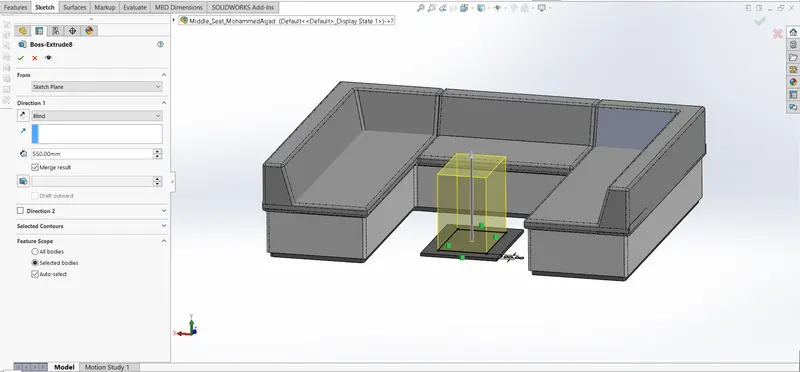
Extrude Boss
The most basic feature from SOLIDWORKS is extrude boss. This feature needs a complete 2D sketch to convert 2D sketch into a solid body. When we exit the fully defined sketch we get boss extrude option and a property manager window pop-up. Into the property manager we see from where the feature begins and where it will end that we need to add dimensions to it. It creates a complete solid body of any shape with closed entities. In this feature we can add dimensions to both the direction (direction 1 and direction 2) according to our need. We can use the direction if it is blind, midplane, from the vertex, etc. This is how we use this feature.
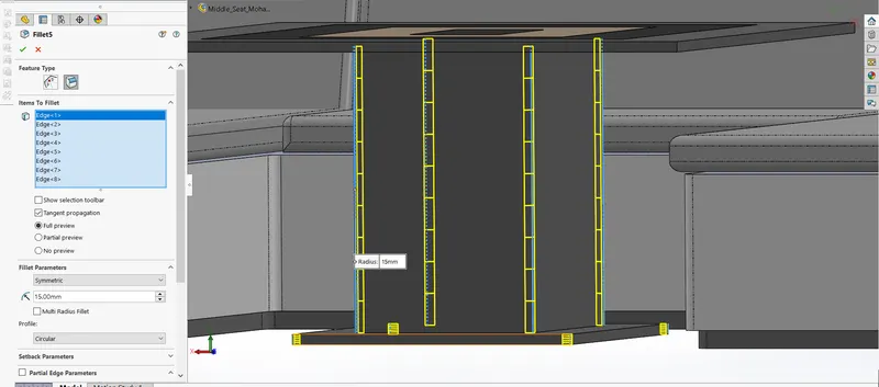
Fillet
When we draw a solid part, it is having some sharp edges. To give the roundness to those edges we add fillets. It makes the sharp edges or corners round shape of having different sizes or radius. The material can be added or removed according to conditions whether edges are internal or external. Fillets are used to solid bodies to hide the corners and edges and also it gives nice appearance to the part. Various types of fillets are used according to the given condition or it depends upon the part.
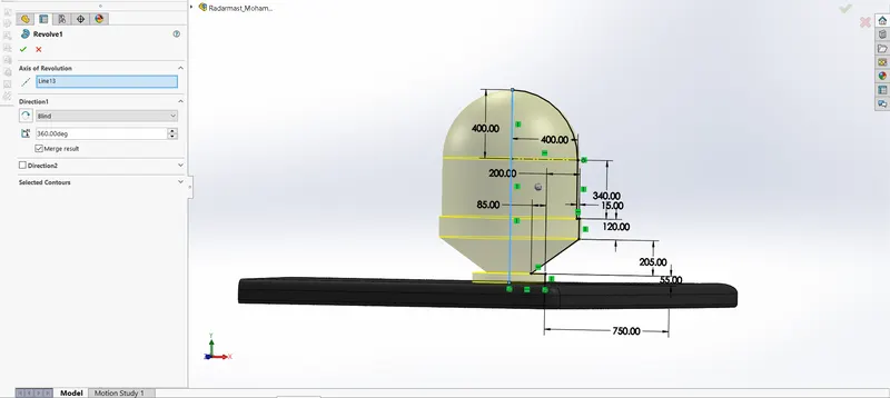
Revolve boss feature
This feature works around an axis, by selecting axis of a sketch it adds a round material by revolving around that axis. If there is no axis we can select an edge of a sketch and it gives us appropriate geometry.
Extrude cut:
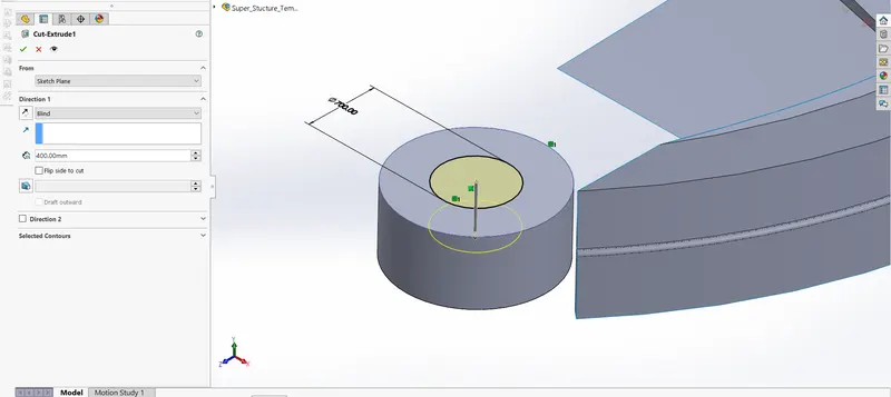
As the name implies, it cuts the geometry which we don’t need from the part or it can be used to give the desired shape to the sketch or solid part. When we draw sketch on the solid part and then we use extrude cut command it removes that part/surface.
Shell
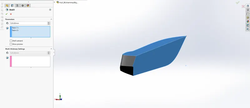
It is very handy tool in SOLIDWORKS. It gives some sort of idea that how inside geometry of a part will appear. In this tool we give inside thickness to the geometry and material removed from the body and it becomes hollow.
Linear pattern
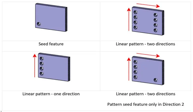
Linear pattern is used to create single sketch to use multiple times. The spacing, angles and path can be given in this feature to draw or create pattern. This feature spaced uniformly along one or two linear paths.
Projected curve
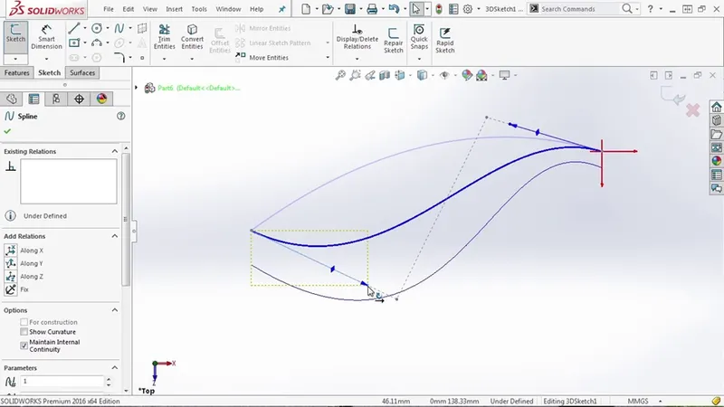
The curve can be project by a sketch into a model to create a 3D curve. We can create multiple closed or open contour projected curves from a single sketch. Generally, the curve can be intersection of two extruding surfaces. The curve which is created can be use as a path for the sketch of the part. Note: It do not create curve of an intersecting curves.
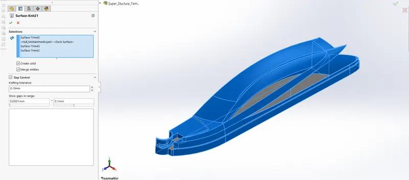
Knit
Use of knit surface tool to combine two or more faces and surfaces into one. It creates a solid body when the knit surfaces form a closed volume or leave as a surface body.
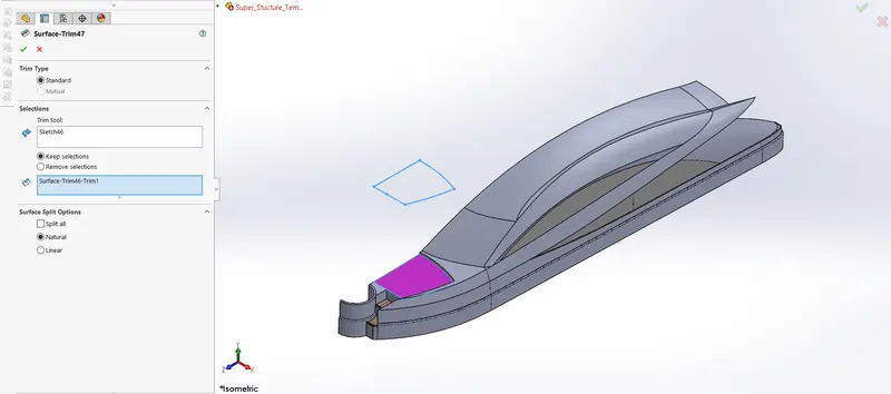
Surface trim
This feature is used to trim the unwanted surfaces from the body. This process can also be vice-versa. In the modelling surfaces, trim places an important role.
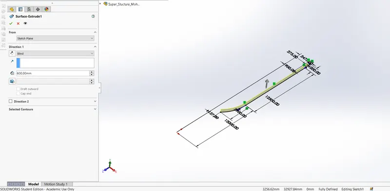
Surface extend
This command is used to fill the gaps between of the body or extent the edge or face from the body. The surface can be extended according our need by giving proper dimension and direction.
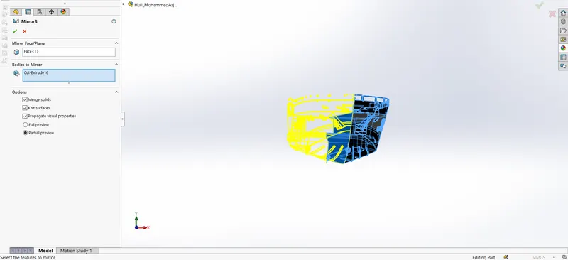
Mirror
This feature mirrors the model as per the reference given. It can also merge and knit the model as per our requirement. This feature makes the modelling process easy. So that we don’t have to design the entire model.
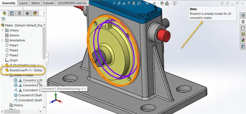
Mate
Mate creates geometric relationship between assembly and component. When we add mates, it defines the allowable direction of linear or rotational motion of component within its degree of freedom, visualizing the assembly’s behavior.
This feature includes:
- Coincident mate: Coincident mate make two planar faces to become coplanar. This mate can move along one another but cannot be separated.
- Concentric mate: This makes two circular faces to become concentric and can move along the common axis.
- Tangent: This feature can be use between a face and plane to make tangent mate.
- Angular mate: This makes angular relation between flat surface and the surface having some angle.
Design and methodology
Blueprint setup
Blueprint is basically a design plan or technical drawings of different orthographic views of a product. The main motto of the blueprint is to bring out the exact same shape and form of the product as designed by a designer. It also ensures the accuracy and the proportion of the product. Designing a product without a blueprint may lead to multiple errors, unnatural proportions and improper dimensions. A proper blueprint setup omits all those problems.
To set up a blueprint, we use sketch mode in SOLIDWORKS in each plane. In this case, the images provided for the front view, side view, top view, back view, and top views are added in respective planes. One very important thing to note while setting up a blueprint is the size of it. As all the parts are going to be designed laying up the blueprint and taking its reference, it is very crucial to maintain the correct and real size of the blueprint in the very first step. It can either be adjusted manually with the dimensions or by adjusting the scale bar.
Components of Yatch
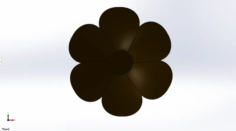
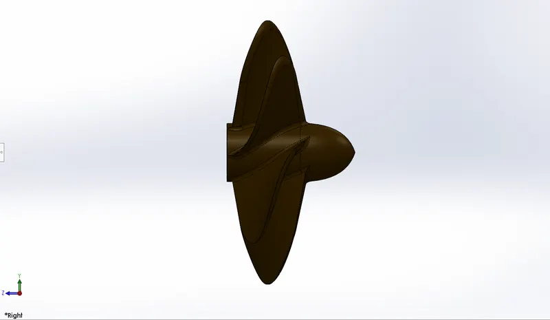
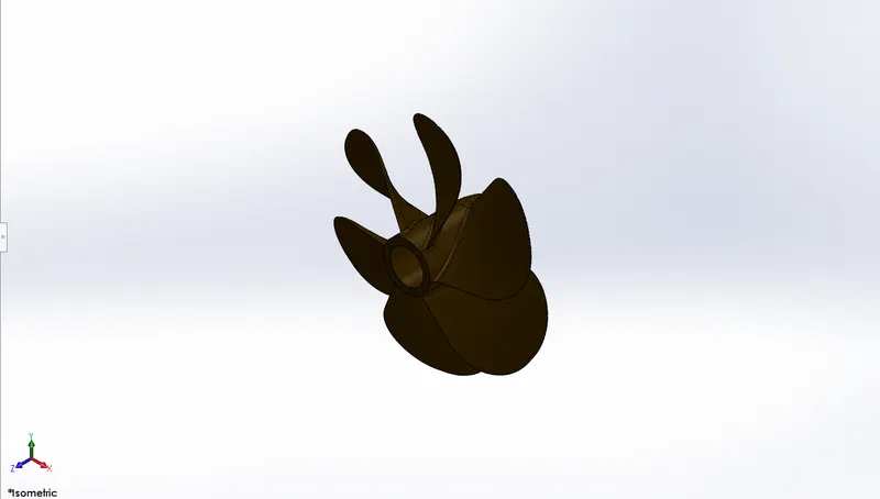
1. Propeller
A propeller is a mechanical device that create thrust over fluid by to propel system. It has serval rotational blades. This component is mainly used in airplanes, submarines and ships to propel them.
In the modelling of Propeller, we used the following tools:
Feature Tools: Revolve Boss/Base, Cut Extrude, Circular Pattern, Fillet.
Sketch tools: Line, spline, 3point comer, rectangle, circle.
Surface Tool: Lofted Surface
No. of Solid bodies:1
Circular Pattern: This feature makes many exact duplicates of selected part and organize it in circular way with equal distance or angle.
Solid Loft: Add material between two or more profiles to create solid bodies.
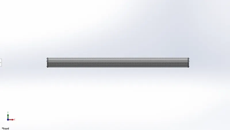
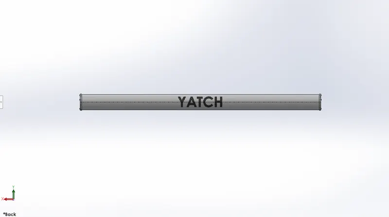
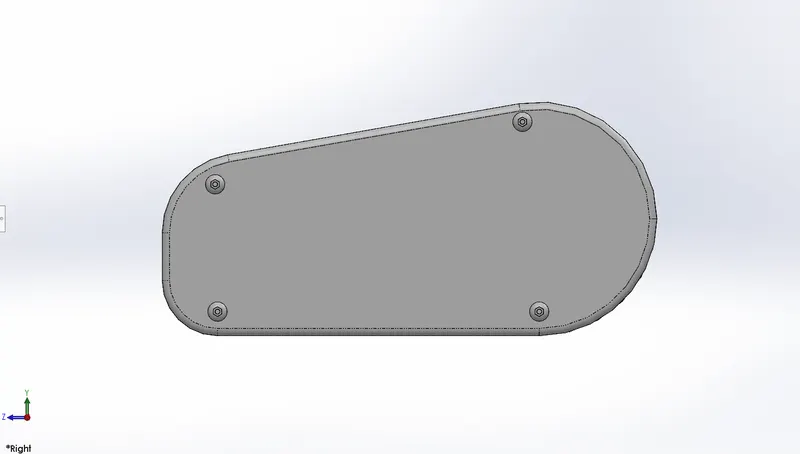
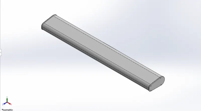
2. Radar
A Radar is an electronic detection system that sends electromagnetic waves to detect angle, range, velocity of object like ship, submarines, aircraft, spacecraft, etc.
In the modelling of Radar, we used the following tools:
Feature Tool: Boss Extrude, Fillet, Cut Extrude, Mirror, Split line.
Sketch tool: Sketch entities, Sketch Pattern.
No. of Solid Bodies: 1
Sketch Pattern: It patterns features, faces, and bodies based on sketch points.
Split line: This creates a break point on line to make a segment into two.
3. Hull
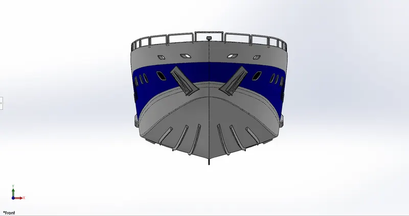
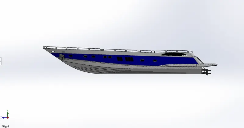
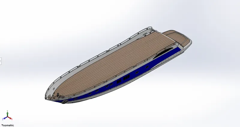
It is the main component of complete Yatch Assembly. Rest of other component will be installed on hull it is like base structure. The hull of a ship directly interacts with water and therefore is the most crucial consideration to a designer. Thus, the hull has to be designed from a pure hydrodynamic point of view. Hardly do we observe a ship which is blandly a box-shaped one. Stability of Ship and ease of construction are also key deciding factors. Designing the precision lines of a hull form keeping in view all these aspects is the bedrock of any form of ship design.
In the modelling of hull, we used the following tools:
Feature tools: Projected curve, Boss-Extrude, Combine, Cut Extrude, Fillet, Chamfer, Swept Boss, Revolve. Dome, Linear Pattern, Helix and Spiral, Delete Face, Shell.
Sketch tools: Sketch Entities, Convert Entities, Offset Entities, trim Entities.
Surface tools: Surface Loft, Surface trim, Surface Extrude, Surface Knit, Surface Fill.
No. of Solid Bodies: 1
No. of surfaces Bodies: 3
Projected curve: The curve can be project by a sketch into a model to create a 3D curve. Projects a sketched curve onto face or sketch.
Composite Curve: It combines two projected curves into a single one
Helix/Spiral: Add a helix or spiral curve from a sketched circle.
Linear Pattern: Create multiple instances of a part sketch in linear way having equal distance as specified.
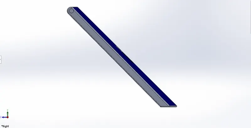
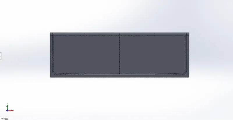
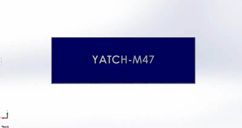
4. Garage door
Garage is used to store vehicle like Bike, car etc. which we want to be. Garage door helps to lock garage space.
In the designing of door, we used the following tools:
Feature Tools: Cut-Extrude, Shell, Fillet, Mirror.
Sketch Tools: Sketch Entities like line, circle, etc.
No. of Solid Bodies: 1
Shell: It removes extra material from solid part to create thin-walled surface and make hollow by adding thickness.
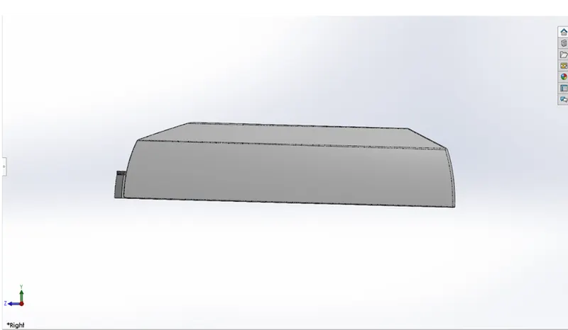
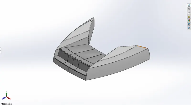
5. Front seat
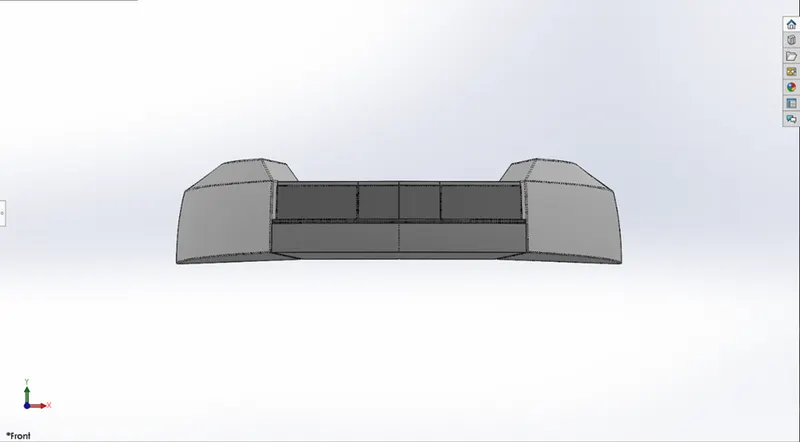
Seats are mean to have rest to occupants. Front seat lies exactly in front of superstructure in between of that we small water pool. Front seat designed using surface features and some of solid features with reference to deck surface. Here we used dome feature to give shape like cushions.
In design of front seat, we used the following tools:
Feature tools: Revolve, Cut Extrude, fillet, Mirror, Dome, Chamfer...
Sketch tools: sketch Entities, Convert Entities.
Surface tools: Inset Surface, Swept Surface, Extrude Surface, Surface Trim, Surface Fill, surface Loft and Surface Knit.
No. of Solid Bodies: 9
No. of Surfaces Bodies: 1
Surface Extrude: This helps to generate or to create a surface from a single sketch entity like line.
Filed Surface: This constructs a surface patch within a boundary defined by curve, edges or sketches of existing model.
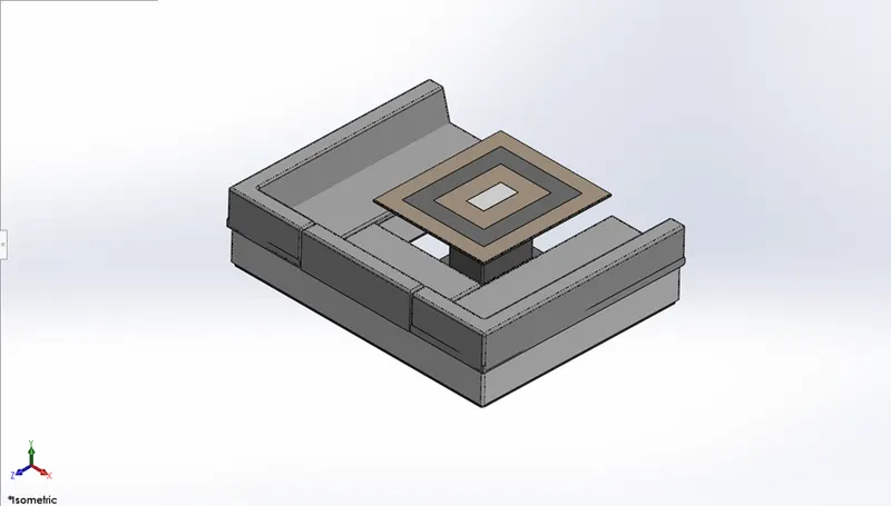
6. Middle seat
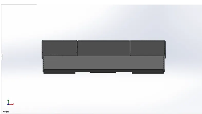
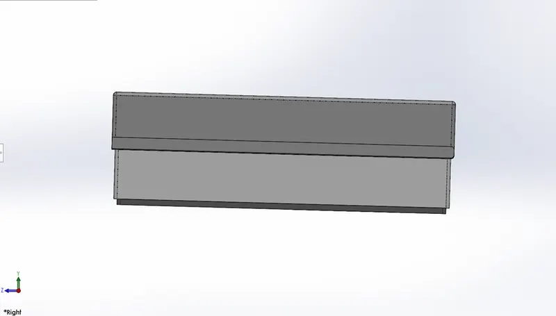
Middle seat is situated next to superstructure. It is modelled with reference to deck surface.
Feature tools: Boss Extrude, Cut Extrude, Mirror, Fillet, Chamfer.
Sketch tools: Sketch Entities, Convert Entities, Offset Entities.
No. of Solid Bodies: 8
No. of Surfaces Bodies: 1
7. Rear seat
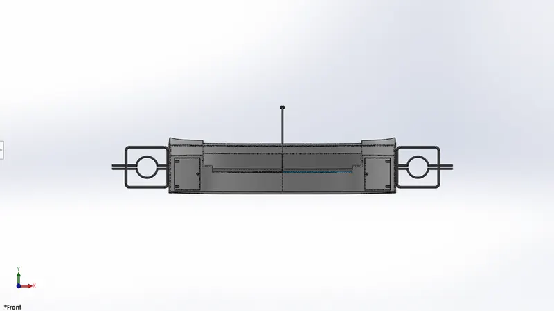
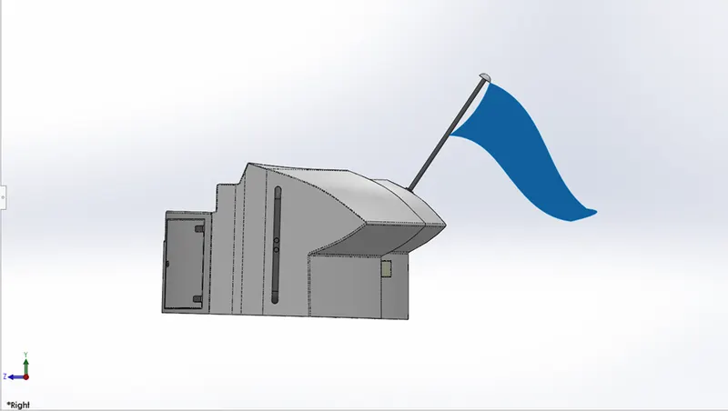
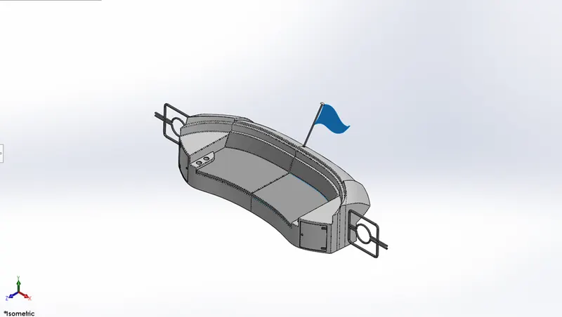
Rear seat located at the end of deck. We used many surface features to model this seat with reference to deck surface. A flag is modelled with 3D sketch giving a real look to it as it show during wind flow.
Feature tools: 3D sketch. Boss Extrude, Cut Extrude, Chamfer, fillet, Swept Boss, Mirror, Revolve.
Sketch tools: Sketch entities, Trim Entities, Offset Entities, Convert entities.
Surface tools: Insert Surface, Swept Surface, Offset Surface, Trim Surface, Ruled Surface, knit surface, Extend Surface, Loft surface.
No. of Solid Bodies: 3
No. of Surfaces Bodies: 4
Offset Surface: This creates surfaces at some distance away as specifies from referenced plane or face.
Extend Surface: This command gives extension to existing surface up to next plane, face, or sketch as specified.
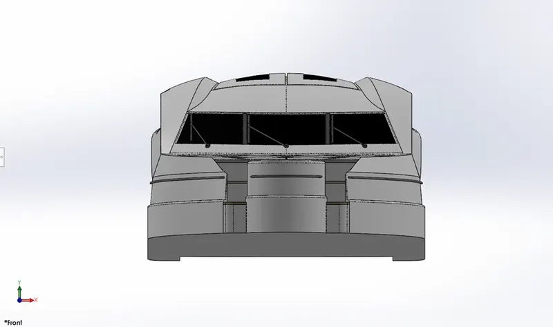
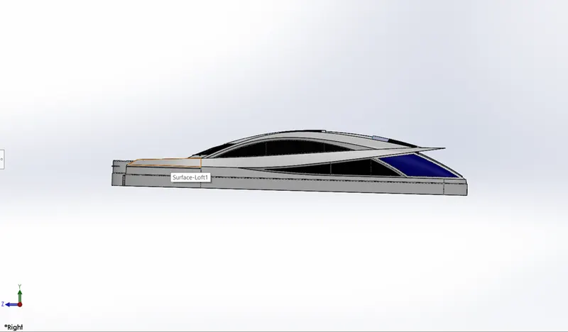
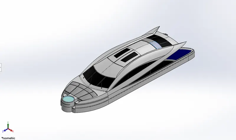
8. Superstructure
It is the extension above deck surface of hull which houses accommodation, offices, Signal and Communication unit, utility spaces, and multifarious electrical and electronic system areas which are indispensable to the operation and the functionality of the ship as well as the sustainability of crew. A good superstructure serves following objectives
- Fulfilment of operational requirement in terms of available volume
- Provision of enough height and space of deck.
In design of superstructure, height plays a crucial part. Height of superstore must enough to provide proper navigational line of sight also it must be in the limit of stability.
In design of superstructure we used the following tools,
Feature tools: 3D sketch, Projected Curve. Boss Extrude, Cut Extrude, Chamfer, fillet. Mirror, Dome.
Sketch tools: Sketch entities, Trim Entities, Offset Entities, Convert entities.
Surface tools: Inset Surface, Extrude Surface, Swept Surface, Offset Surface, Trim Surface, Ruled Surface, Knit surface, Extend Surface, Loft surface. Surface Fill, Delete Face.
No. of Solid Bodies:
No. of Surfaces Bodies: 2
Swept Surface: Creates surface feature by sweeping an open or closed profile along an open or closed path.
Ruled surface: Inserts ruled surfaces from edges.
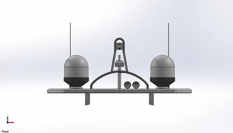
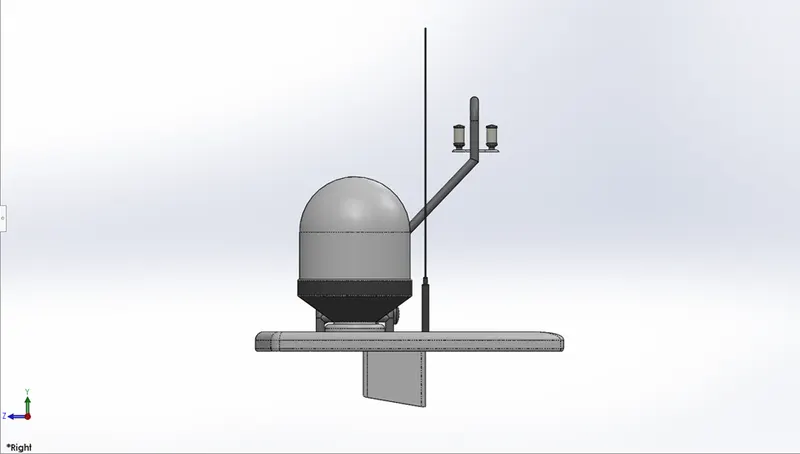
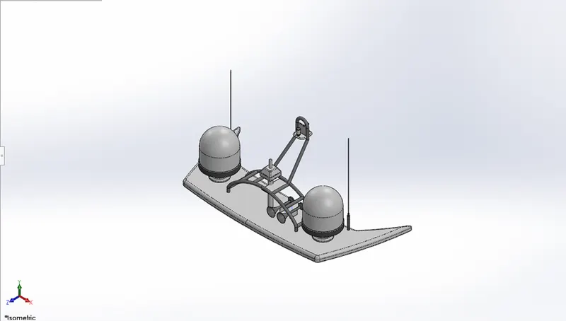
9. Radarmast
A mast system is composed mainly of supporting frames, a C shape base plate, radar (transmitter and receiver), and an antenna. This modelled with reference to superstructure top surface. Base plate supports all equipment components over it.
In modelling of Radarmast, the following tools are used:
Feature tools: 3D sketch, Projected Curve, Boss Extrude, Shell, Chamfer, fillet. Mirror, Dome, Revolve
Sketch tools: Sketch entities, Trim Entities, Offset Entities, Convert entities.
No. of Solid Bodies: 2
No. of Surfaces Bodies: 2
Dome: It provide a dome like shape to one or more faces which can be planner or non-planer.
10. Assembly
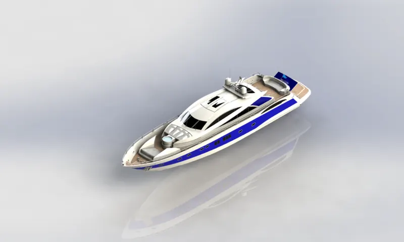
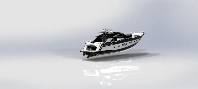
Assembling is a process in which individual components of a system are placed together to form a complete system that we worked as desired to. The hull acts as the main body for assembly. All parts are fixed with reference to the hull. Every component we modelled is inserted to the assembly file and given mate relation according to our need.
Mate Feature:
This feature creates a geometric relationship between two parts. To define it with reference to part we add relation like linear, parallel. concentric, rotational which fix the part in proper way and according requirements.
11. Photorealistic Rendering
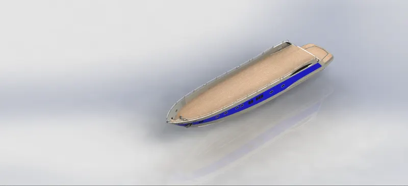
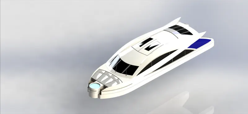
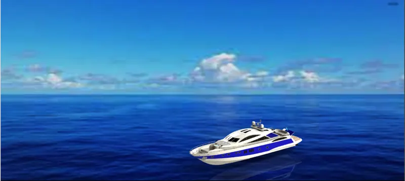
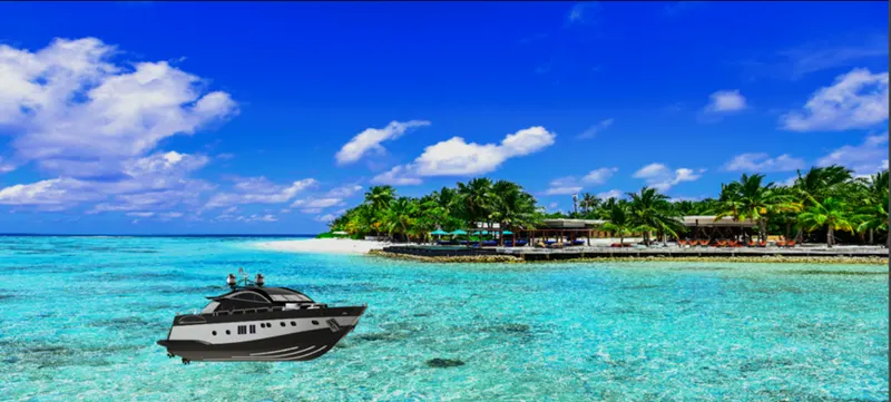
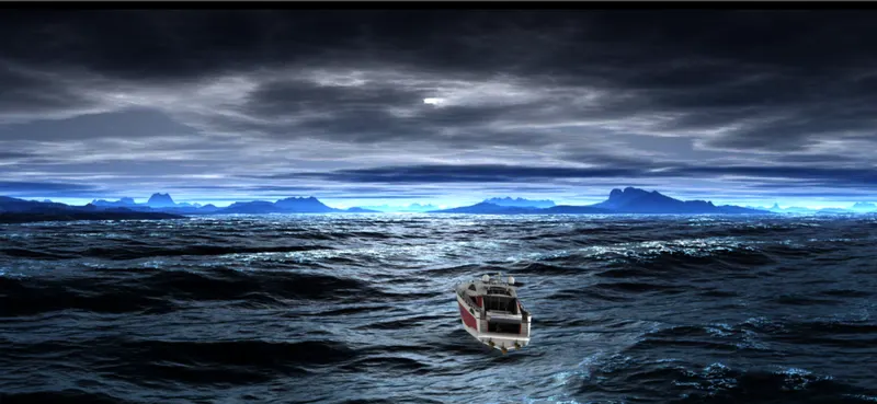
Rendering: It is the process of creating a realistic view which has everything a real. In this process we add Decals, Environment. background, adjust lights to focus for specific view hence giving a reality look as it is when physically places in such environments.
For Rendering we have options like:
Solidworks Visualize
Photo-view 360
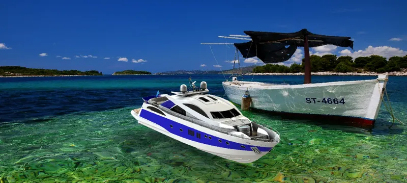
For rendering of Yatch We used Photo-view 360
Some of the rendered images are shown below


Conclusion
Hence, we learnt to design, assemble and render the yatch using SOLIDWORKS. We also used several types of tools, features, decals, lights and camera throughout the project.
Last but not least, I would like to thank my support engineer and the entire Skill-Lync team for their support throughout the course and for the smooth learning process.