Week 11 Challenge
1. Aim: To calculate the Friction load on the axis.
Given data:
Vertical force at the pipe support=125 kN.
Solution:
Considering the pipe material and support material to be carbon steel.
So the coefficient of friction is considered as 0.3 for a single pipe running case.
Friction load on the support in the longitudinal direction of pipe =0.3 x 125 = 37.5 kN
Friction load on the support in the transverse direction of pipe= 10% of pipe operating loads =0.1 x 125 =12.5 kN
If Teflon is used in-between pipe and support, then the friction coefficient will be 0.1.
Friction load on the support in the longitudinal direction of pipe =0.10 x 125 = 12.5 kN
Conclusion:
Friction load on pipe support on longitudinal & transverse directions are found to be 37.5 kN & 12.5 kN respectively.
2. Aim: To identify the type of pipe support from the attached figures.
Solution:
a)
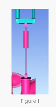
It can be seen from the figure above that the pipe is hung from the top with a spring, so it is spring support.
b)
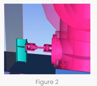
It can be seen that it is guide support in which movement of pipe in the transverse direction is allowed.
c)
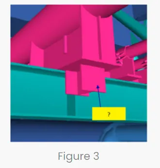
It can be seen that It is (transverse guide support + rest )in which movement of pipe in the transverse direction is allowed and movement in longitudinal & vertical direction is restrained.
d)
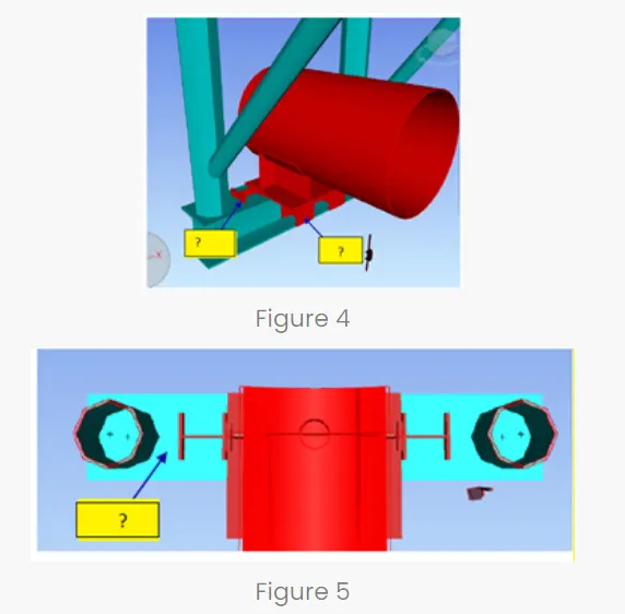
It can be seen that, In this support, there is restraint in movement in longitudinal, transverse & vertical directions.It can be called as semi anchor support.
d)
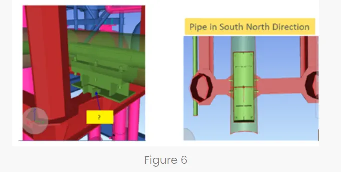
It can be seen that along with movements in all directions, rotations are also restrained in all directions.So it can be called as anchor support.
Conclusion:
All support types were identified.
3.Aim: To design a typical pipe rack bent in oil plant.
Solution:
Staad model was prepared as per the given data.
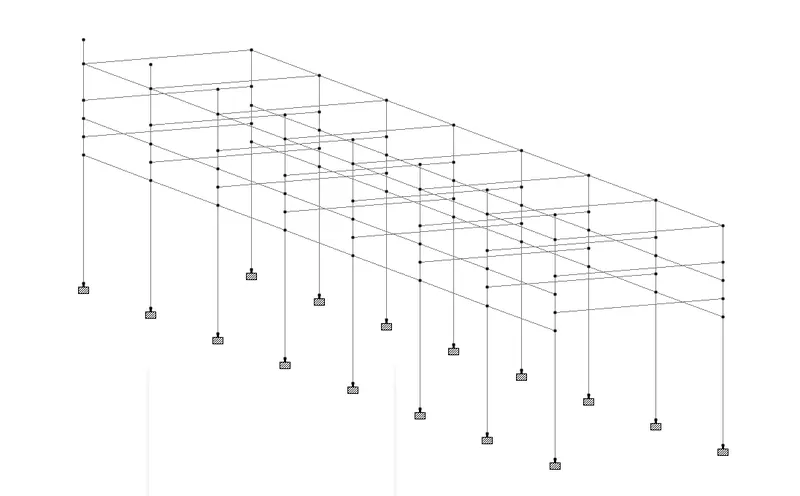
Then different load cases are prepared and load were applied.
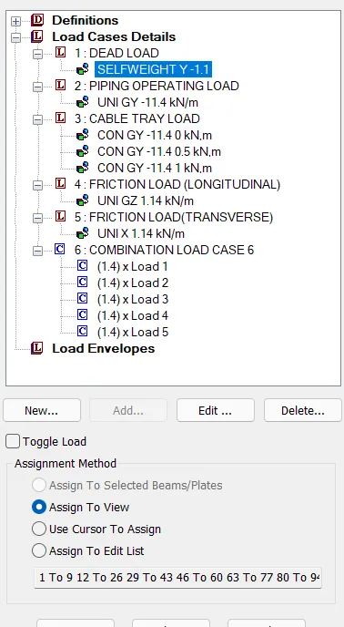
- For pipe operating load, 1.9 kN/m2 is considered & bay spacing is 6 m so Pipe operating load =1.9x6=11.4 kN/m
- For cable tray load ,1.9 kN/m is considered and considering bay spacing as 6 m, concentrated load is found to be 1.9*6 =11.4 kN
- Then friction load in both longitudinal and transverse direction is taken as 10 % of the pipe operating load.
- Then load combination with factor 1.4 is added by considered all load cases.
- Then different design parameters were assigned to the members of the structure as shown below.
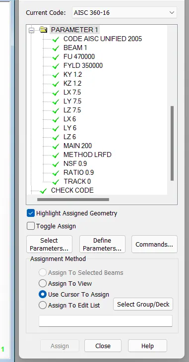
- The member properties considered are
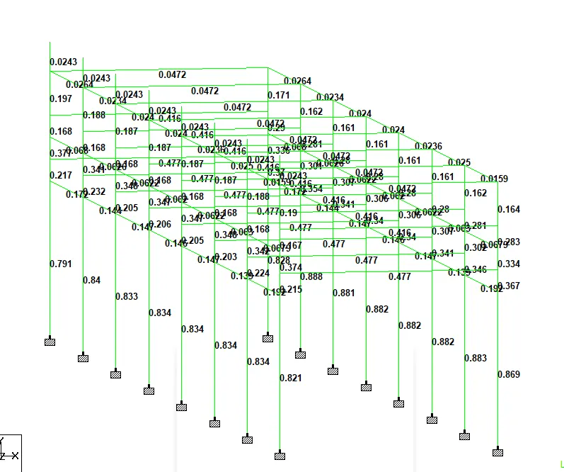
Column - ISHB 250,Main beam-ISHB 350 & Logitudinal struct-ISHB 250.
The utilization ratio of each member can be seen below.
Conclusion:
The member properties for Column, Main beam & Longitudinal struct are ISHB 250, ISHB 350 & ISHB 250 respectively.