Week 4 Challenge
Aim- To calculate the earth pressure being applied on the abutment and do the structural analysis in staad pro.
Given data-
Height of ground level from the top of the footing of the abutment (h1)-3 m
Height of backfill (h2) -7 m
Length of abutment -5 m
The water table is at Ground level.
The depth of the abutment footing (d1) -1 m.
Solution:
Assume at rest condition for backfill and active condition for the soil outside the abutment for calculation of earth pressure.
Ko=0.5 & Ka=0.33
Unit weight of soil (γ)-18 kN/m3, Unit wt of water (γw)- 10 kN/m3
i) Earth pressure due to backfill on the bottom of abutment wall = Ko * γ * h2=0.5 * 18 * 7 =63 kN /m2
ii) Vertical Earth pressure on the inside projection of the footing due to backfill= γ * h2 = 18 * 7 =126 kN/m2
iii) Earth pressure on the bottom of abutment wall from outside = Ka * ( γ - γw) * h1 = 0.33 * (18-10) * 3 =7.92 kN/m2
iv) Water load on the bottom of abutment wall from outside = γw * h1 =10 * 3 =30 kN/m2
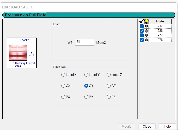
v) Vertical Earth pressure on the outside projection of the footing = γ * h1 = 18*3 = 54 kN/m2
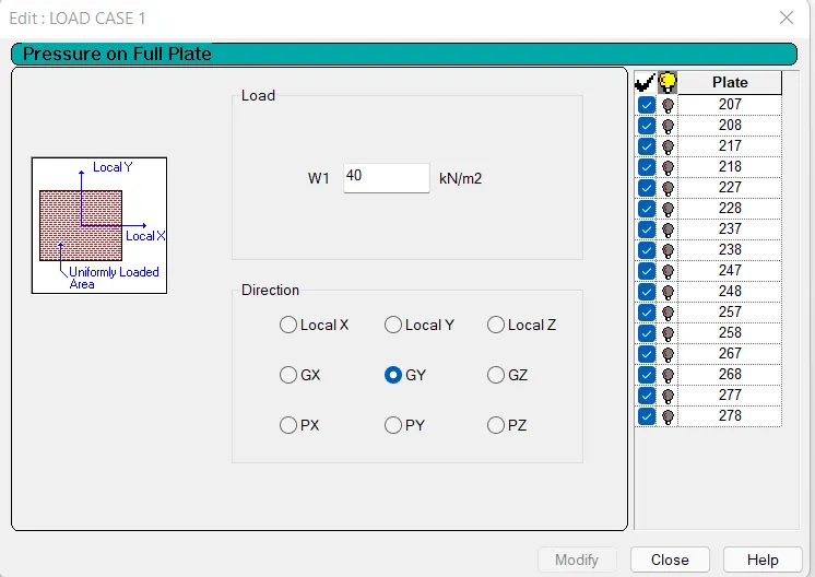
vi) uplift pressure on the footing = (h1 + d1) * γw =(3+1)* 10 =40 kN/m2.
Structural analysis in staad pro
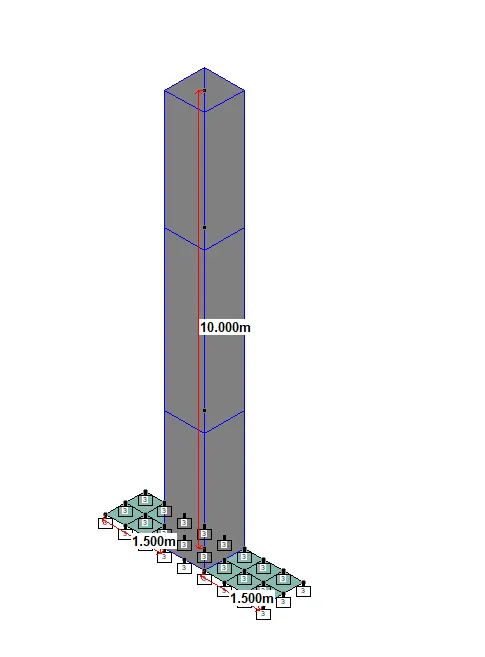
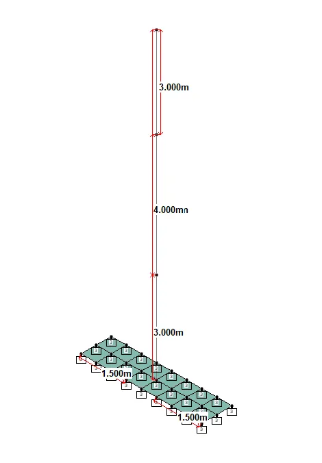
In Staad pro, a model is prepared by considering the unit length of abutment and footing (per meter).
The height of the abutment wall is assumed as 10 m and the footing overhang is assumed as 1.5 m from the face of the abutment wall.
The per meter model prepared in staad pro is shown below.
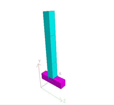
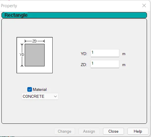
The section for abutment is considered to be 1m in width & 1 m in length.
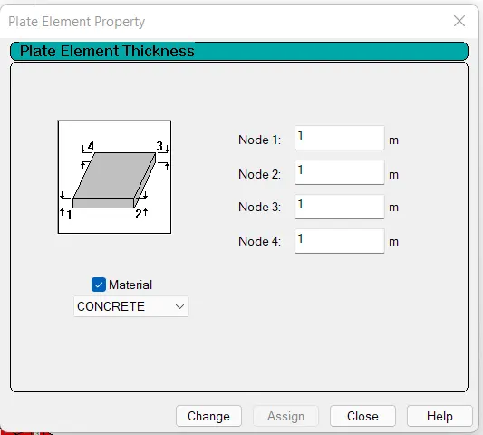
The thickness of the footing is considered as 1 m.
The support is considered as the foundation of plate type and the subgrade modulus is considered to be 10000 kN/m2/m.
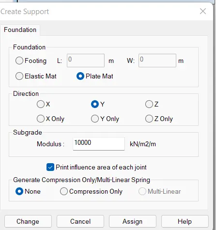
The support is assigned to the footing plates.
Then a load case is created to apply the loads as calculated above.
As unit length (Per meter) is considered ,all the loads are applied as UDL or UVL on the abutment wall as per the requirement.
And the vertical earth pressure and uplift pressure are applied as plate loads.
To apply the loads, the abutment is discretized into 3 different elements.
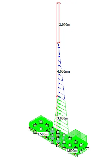
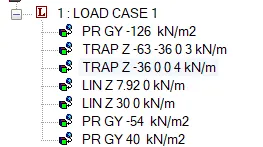
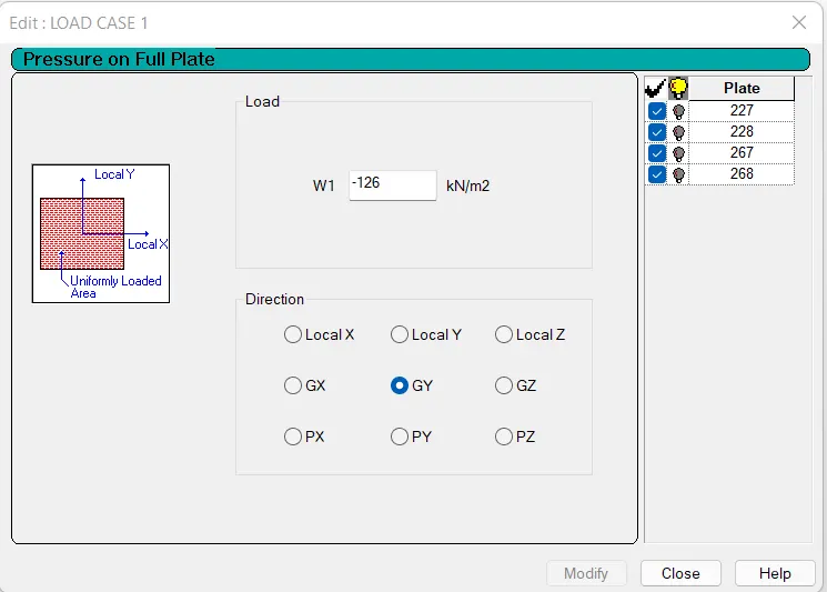
- 126 kN/m2 is applied as a plate load.
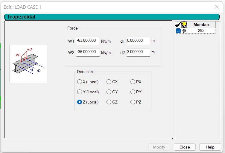
- The trapezoidal load was considered for applying earth pressure of 63 kN/m (as per meter width) at the bottom and zero at 7 m from the bottom.
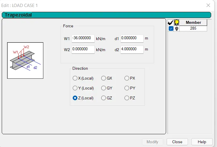
- 7.92 kN/m is applied as a linearly varying load from 0 to 3 m in the outer face of the abutment wall.
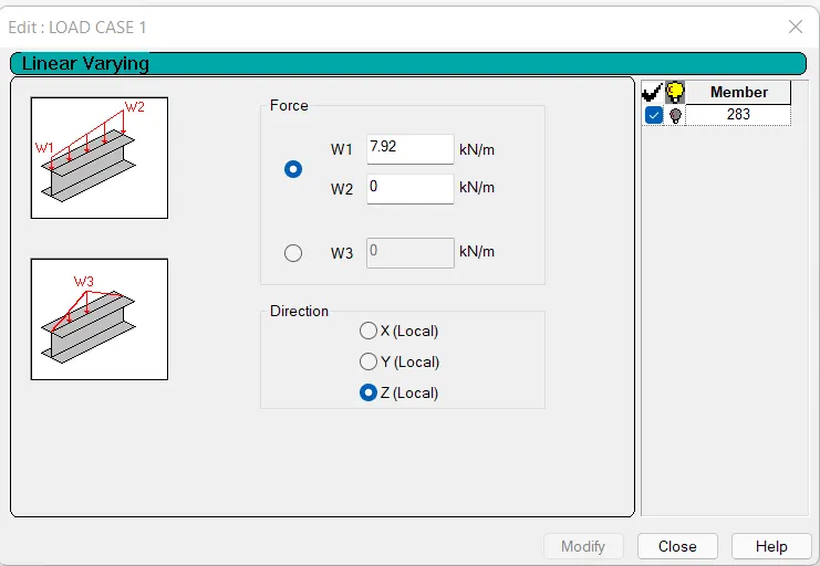
- 30 kN/m is applied as a linearly varying load from 0 to 3 m in the outer face of the abutment wall.
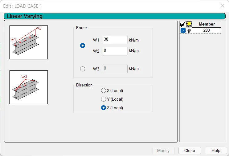
- 54 kN/m2 is applied as the plate load in the vertical direction in the outer overhang of the footing.
- Uplift load of 40 kN/m2 is applied as vertical plate load on the full footing.
Results:
Bending Moment in abutment wall,
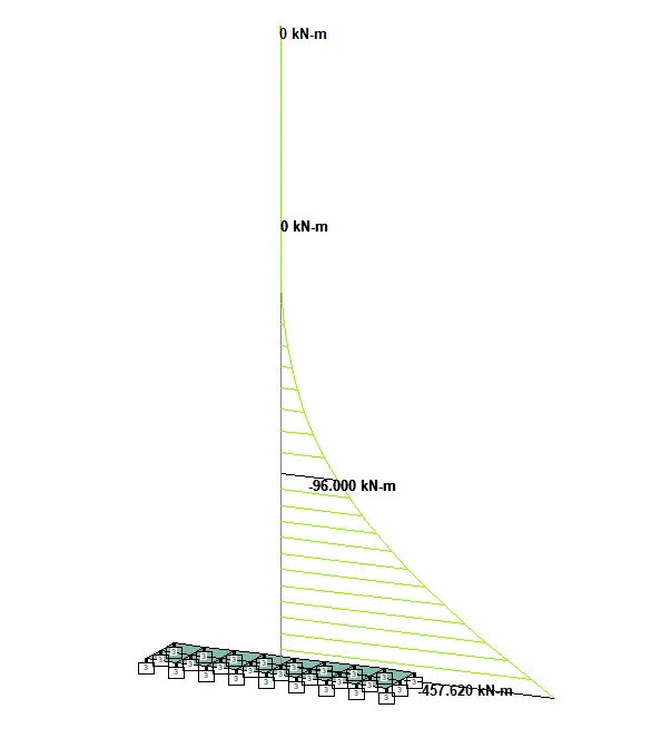
Maximum Bending moment observed - 457.62 kN.m/m (As only per meter width is considered)
Maximum shear force in abutment wall,
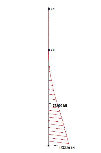
Maximum shear force observed - 163.62 kN/m (As only per meter width is considered)
Maximum Bending moment in Footing,
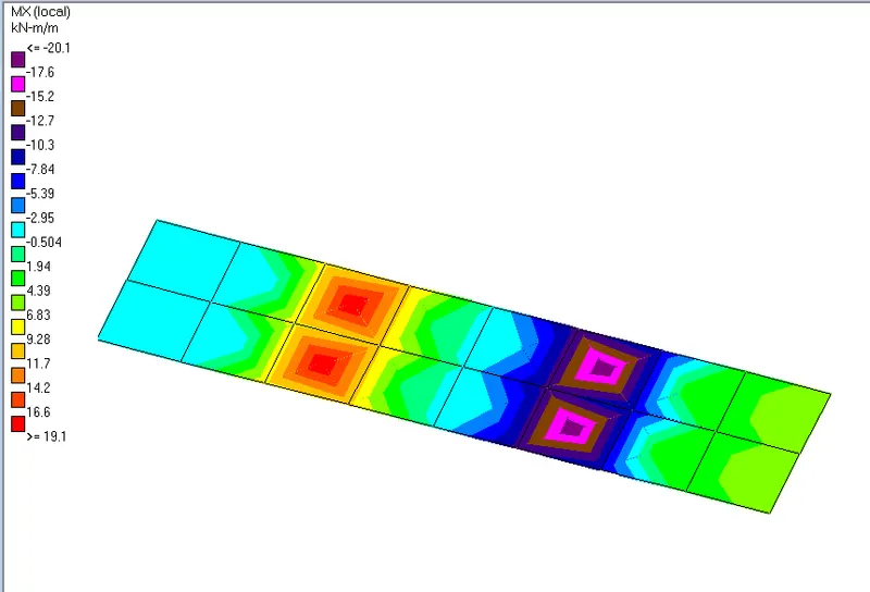
(Bending moment (Mx))
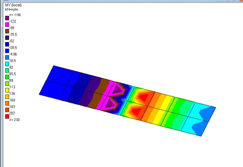
(Bending moment (My))
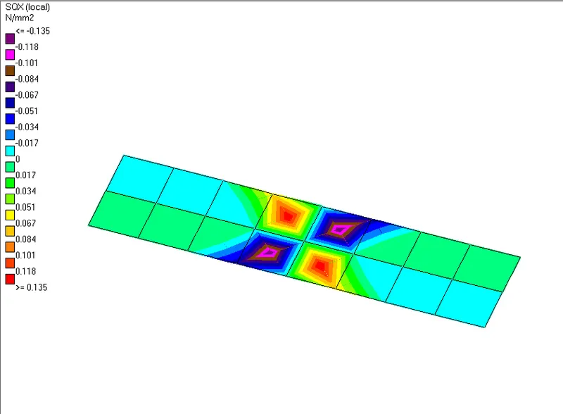
Shear (SQx)
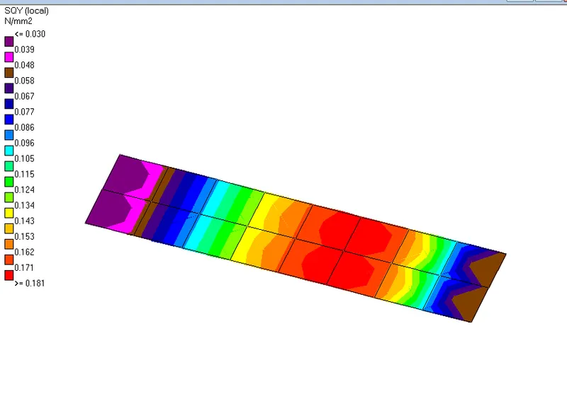
Shear (SQy)
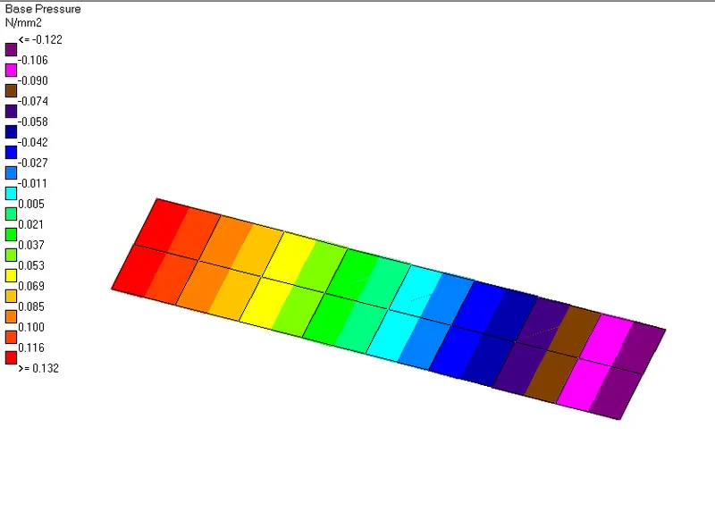
(Base Pressure)