Week 3 Challenge
Aim: To model and analyze the I girder bridge in Staad pro with IRS loading.
Given data:
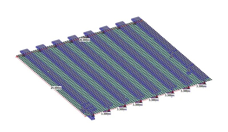
Width of bridge deck - 26 m
The span of the bridge -25 m
Solution:
Model of the bridge
- The superstructure part of the bridge has been modeled in Staad pro according to the figure provided in the question.
- Properties of the bridge components are considered as follows.
- Bridge deck thickness is considered 200 mm.
- The c/c distance between the I girder is considered as 3.3 m.
- A simply supported condition has been adopted as the support condition of the bridge.
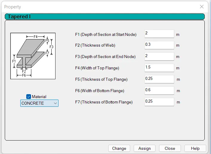
- I type girder properties have been considered as follows.
- The model of the bridge is attached below.
IRS loading
A total of 5 types of loads have been considered for the analysis.
In the bridge deck, There are a total of 4 lanes are considered. In two adjacent lanes on the left side of the deck, two moving loads will move in the same direction & other two adjacent lanes on the right direction will be loaded with moving loads moving in the opposite direction.
The same loading arrangement has been adopted for all the 5 IRS loading cases.
i) Broad gauge loading.
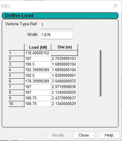
Loading has been defined in vehicle definition as shown below.
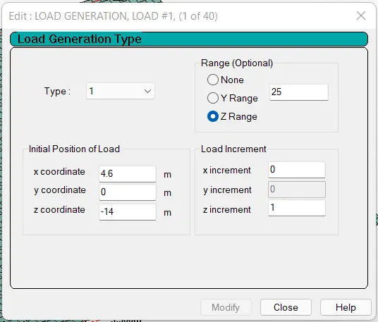
A total of 40 load cases are generated.
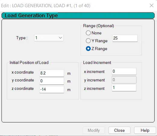
The lane at the left end of the bridge deck is loaded as shown by setting the z increment as 1 and setting the initial position of a load of 4.6 m from the left end of the bridge deck by considering shoulder length and Footpath clearance.
The adjacent lane to the extreme left lane is loaded with adjustment in x-coordinate.Here the X- coordinate has been chosen as 4.6 m +3.6 m (width of a lane)=8.2 m.
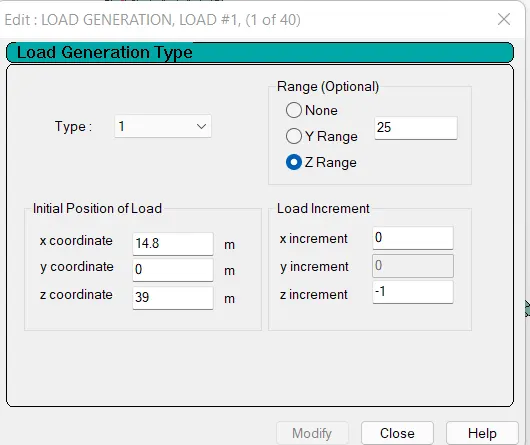
The other two lanes are loaded such that there will be moving loads in the opposite direction by considering load increment as -1. Here, X -the coordinate value has been chosen considering 8.6 m +3.6 m(width of a lane) +2*1.3 m (clearance at middle)=14.8 m
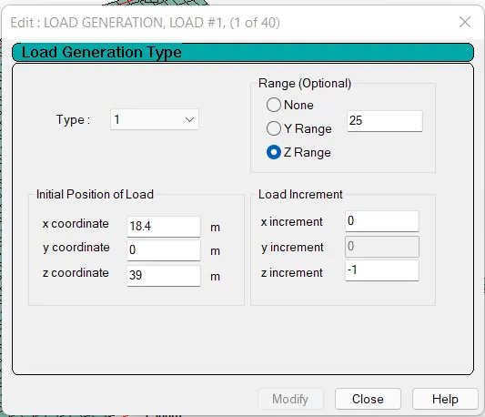
Similarly, the extreme right end lane is also loaded with moving load by considering X-coordinate as 18.4 m i.e 14.8+3.6 m.
2) Electric Train Loading
The loading details is added as shown in the vehicle definition.
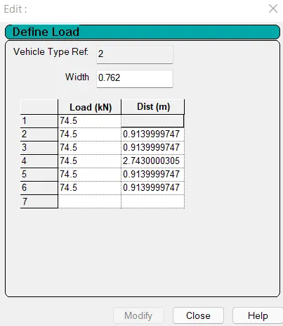
Load case generation is followed similar to 1st case.
3) Gauge A loading
The loading details are added as shown in the vehicle definition.
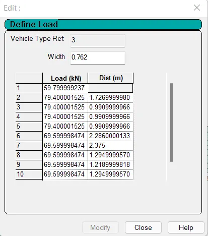
Load case generation is followed similar to 1st case.
4) Gauge B loading.
The loading details are added as shown in the vehicle definition.
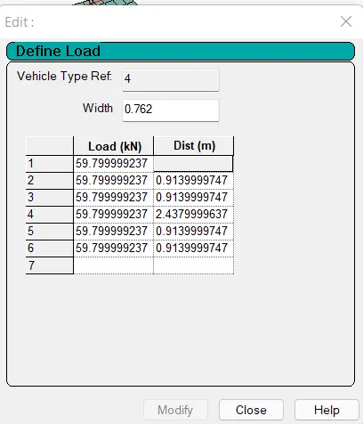
Load case generation is followed similar to 1st case.
5) Metro rail loading.
The loading details are added as shown in the vehicle definition.
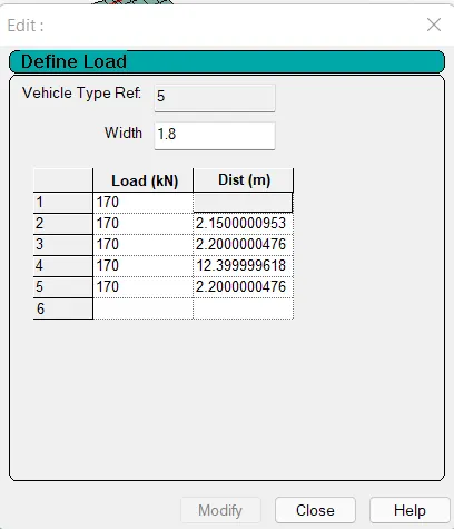
Load case generation is followed similar to 1st case.
Structural Analysis & Results
All 5 load cases were applied and analyzed in staad pro. The result of the analysis will be shown for each load case separately one by one.
i) Broad Gauge Loading
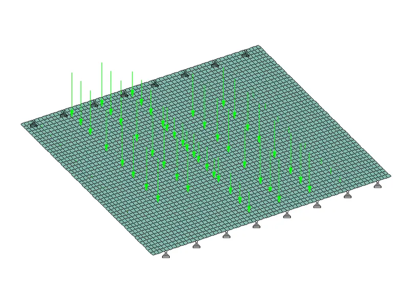
(Moving Load Diagram)
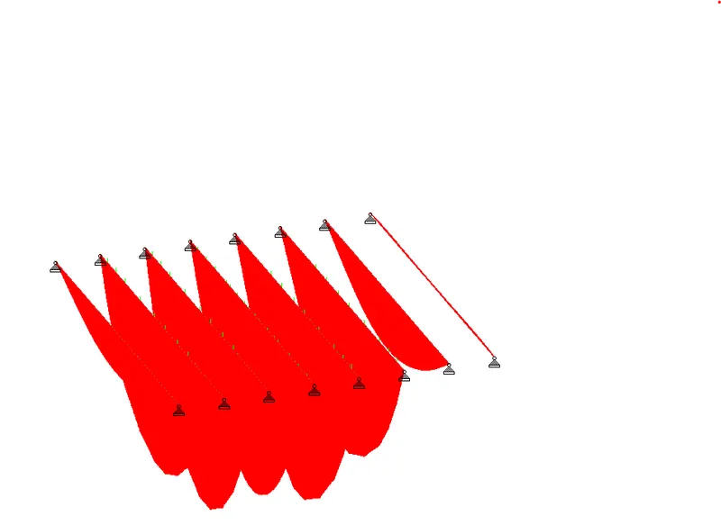
(Bending Moment Diagram)
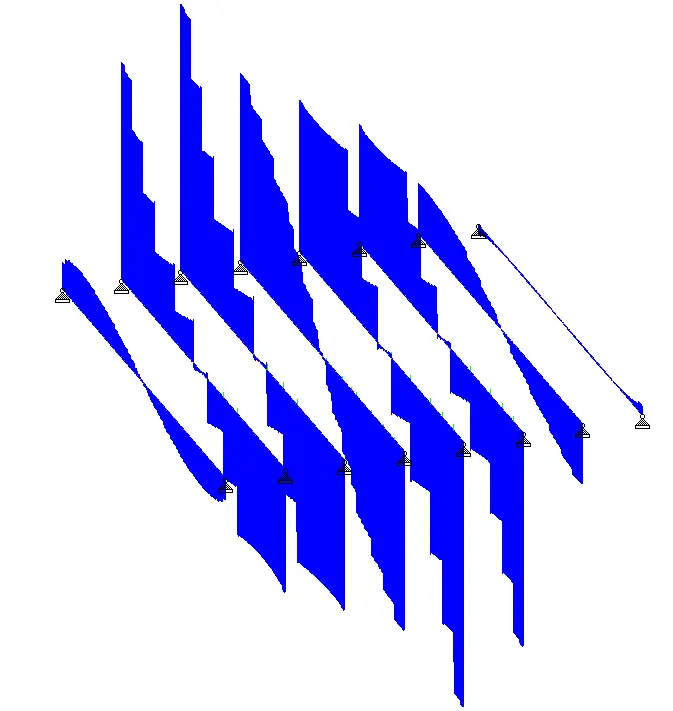
(Shear Force Diagram)
Results:
Maximum Bending moment observed in the Girder - 9767.136 kN.m
Maximum Shear Force observed in the Girder - 1735.178 kN
Maximum Bending moment observed in the deck - 87.795 kN.m
ii) Electric Train Loading
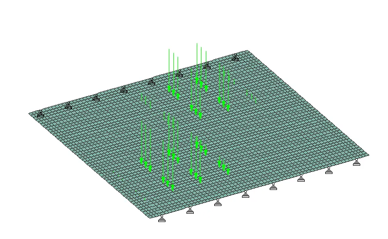
(Moving Load Diagram)
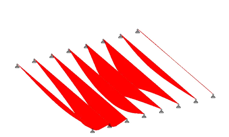
(Bending Moment Diagram)
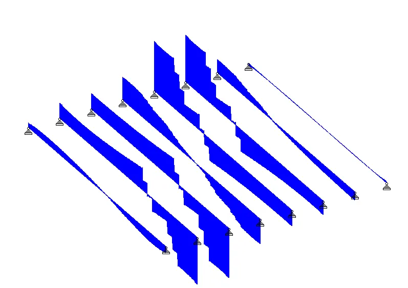
(Shear Force Diagram)
Results:
Maximum Bending moment observed in the Girder - 3211.915 kN.m
Maximum Shear Force observed in the Girder - 666.705 kN
Maximum Bending moment observed in the deck - 30.374 kN.m
iii) Gauge A Loading
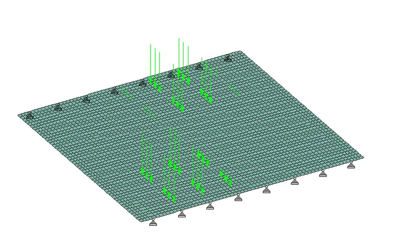
(Moving Load Diagram)
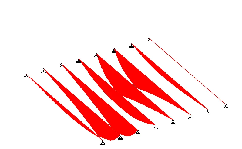
(Bending Moment Diagram)
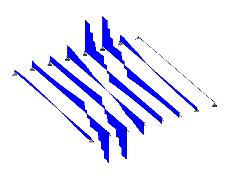
(Shear Force Diagram)
Results:
Maximum Bending moment observed in the Girder - 4848.43 kN.m
Maximum Shear Force observed in the Girder - 882 kN
Maximum Bending moment observed in the deck - 46.806 kN.m
iv) Gauge B Loading
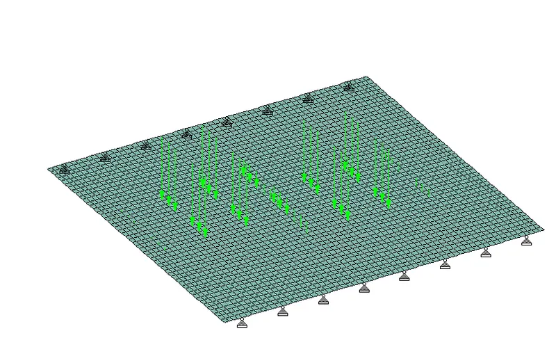
(Moving Load Diagram)
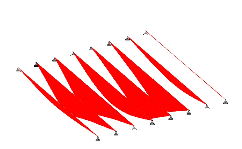
(Bending Moment Diagram)
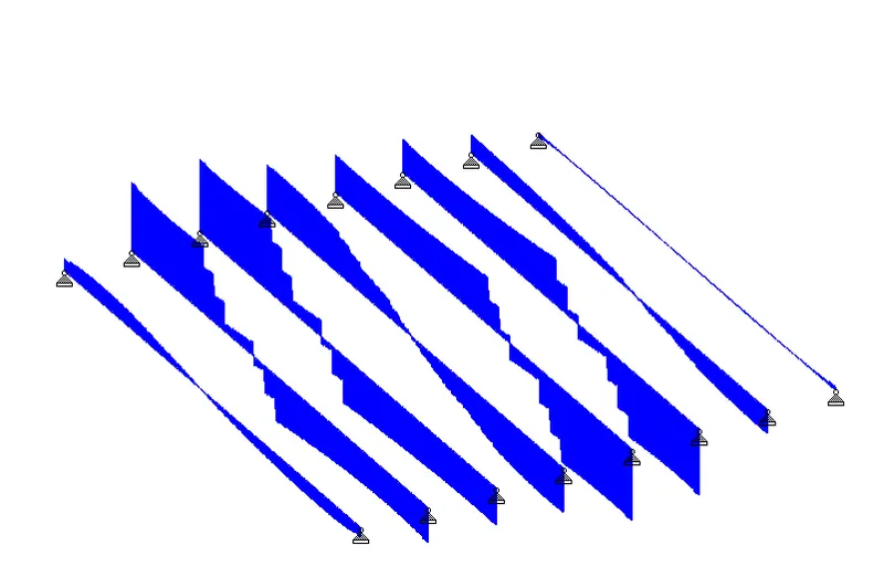
(Shear Force Diagram)
Results:
Maximum Bending moment observed in the Girder - 2870.64 kN.m
Maximum Shear Force observed in the Girder - 540.021 kN
Maximum Bending moment observed in the deck - 25.602 kN.m
v) Metro rail loading
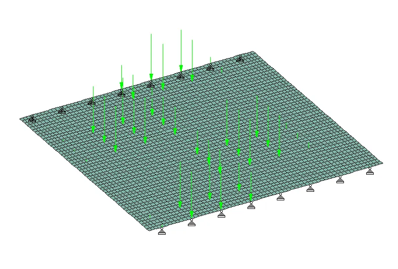
(Moving Load Diagram)
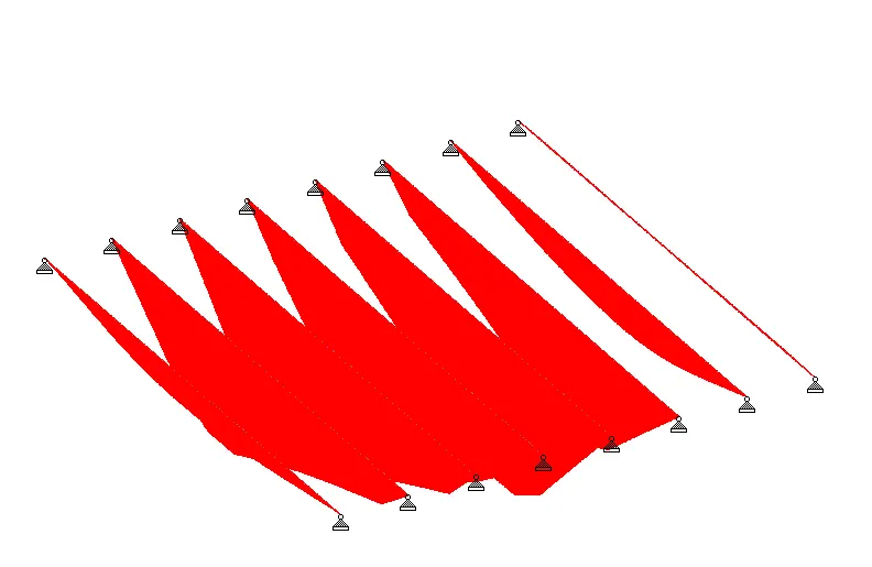
(Bending Moment Diagram)
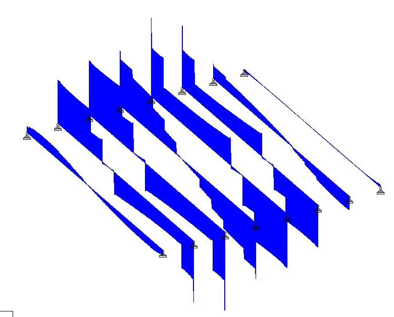
(Shear Force Diagram)
Results:
Maximum Bending moment observed in the Girder - 4535.89 kN.m
Maximum Shear Force observed in the Girder - 968.185 kN
Maximum Bending moment observed in the deck - 35.39 kN.m