Week 2 Challenge
Aim: To apply the IRC live load on the given bridge deck.
Given data:
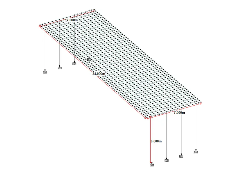
The span of the bridge-24 m.
Diameter of pier- 6 m.
Width of bridge deck-7 m.
C/C distance between the Cross girder-8 m.
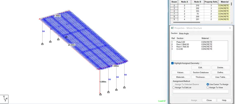
C/C distance between main girders-1.9 m.
The thickness of the deck is -200 mm
Section size of the Main girder - 500 mm x 1900 mm.
Section size of the cross girder - 300 mm x 1700 mm.
Assume, Height of the pier is 10 m.
Solution:
STAAD MODELLING OF BRIDGE:
- With the given data, staad model was prepared.
- Then the property is assigned to each component of the bridge.
- The fixed condition has been assumed for the end of the pier.
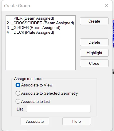
- Group has been defined for each component of the bridge.
APPLYING LIVE LOAD ON THE BRIDGE:
There are 3 live loads to be applied to the bridge deck,
i) IRC class A (Type-1)
ii) IRC class B (Type-2)
iii) IRC class 70R (Type-3)
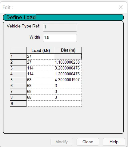
- To apply the vehicular live load, choose the vehicle definition option and the details like axle load and distance between the load points were given as input per IRC 6.
- Three types of loads were created accordingly.
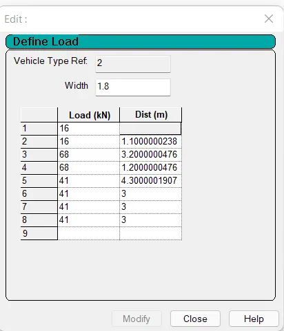
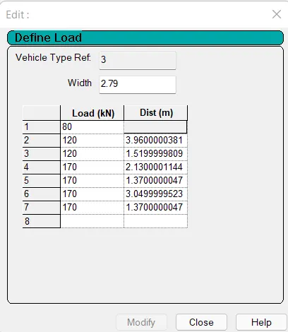
- As the carriageway width is more than 5.3 m, As per table 6A of IRC 6, Multiple load combinations has to be applied.
- So according to Sl. no.2 of table 6A, 3 load combinations have been defined.
- Two IRC class A loads on the deck.
- Two IRC class B loads on the deck.
- Single IRC 70R load on the deck.
- As per table 3 of IRC 6, the clear distance between two IRC class A load has been considered as 1.2 m.
- Similarly, for IRC class B load, 1.2 m has been considered as the clear distance as per table 5 of IRC 6.
- The clear distance between the kerb and vehicle has been considered as 150 mm for IRC class A & IRC Class B vehicles.
- For IRC 70R load, the clear distance between the kerb and vehicle has been considered as 1.2 m
Considering the above-mentioned points, 3 different Moving load cases are generated.
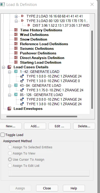
- Load combination of IRC class A,
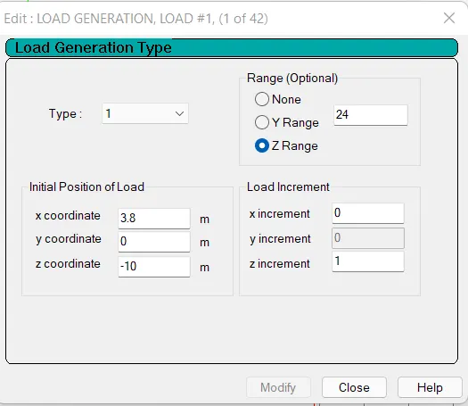
- By considering the span of the bridge as 24 m and the length of the vehicle as 18.8 m and considering the load increment as 1 , a total of 42 load cases have been generated.
- For 1st vehicle, x-coordinate as choosen as 0.8 m by considering the deck overhang( walkway) as 0.65 m+ 0.15 (clearnace)=0.8 m.
- The range has been defined as the span of the bridge and Z increment as 1.
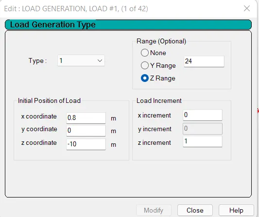
- Similarly for 2nd IRC class A load, x-coordinate has been chosen considering 0.8 m (clearance of the 1st vehicle) + 1.8 (width of vehicle) + 1.2 m (clearance between vehicle ) =3.8 m.
- Load combination of IRC class B,
As the width & length of class A and class B vehicle is the same, similar to class A load combination, The load combination for class B vehicle is created.
- IRC 70R load on the bridge deck,
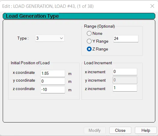
- By considering the span of the bridge as 24 m and the length of the vehicle as 14.3 m and considering the load increment as 1, a total of 38 load cases have been generated.
- For 1st vehicle, the x-coordinate as chosen as 0.8 m by considering the deck overhang( walkway) as 0.65 m+ 0.1.2 m (clearance)=1.85 m.
- The range has been defined as the span of the bridge and Z increment as 1.
STRUCTURAL ANALYSIS AND RESULTS:
After using the performance command, the following results have been found. It has been given shown separately for 3 different load cases.
i) Combination of IRC class A load,
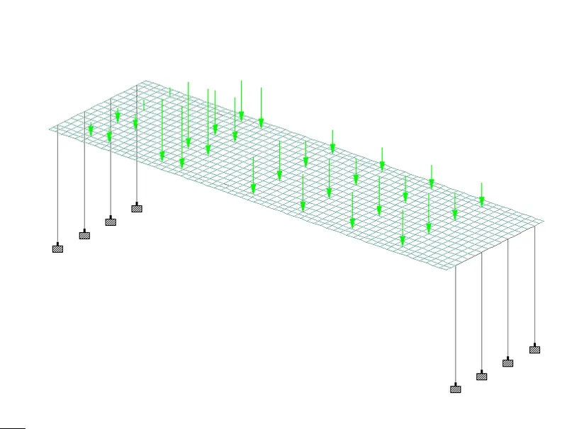
(Moving Load diagram)
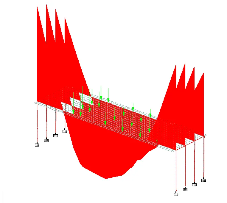
(Bending Moment Diagram)
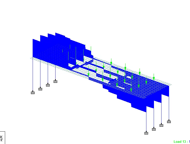
(Shear Force Diagram)
Summary:
Cross Girder:
Maximum Positive Bending Moment: 15.659 kN.m
Maximum Negative Bending Moment: 116.528 kN.m
Maximum shear force: 48.746 kN
Main girder:
Maximum Positive Bending Moment: 1389.89 kN.m
Maximum Negative Bending Moment: 961.641 kN.m
Maximum shear force: 453.103 kN
Pier:
Maximum Bending Moment: 1396.51 kN.m
Maximum axial force: 464.68 kN
ii) Combination of IRC class B load,
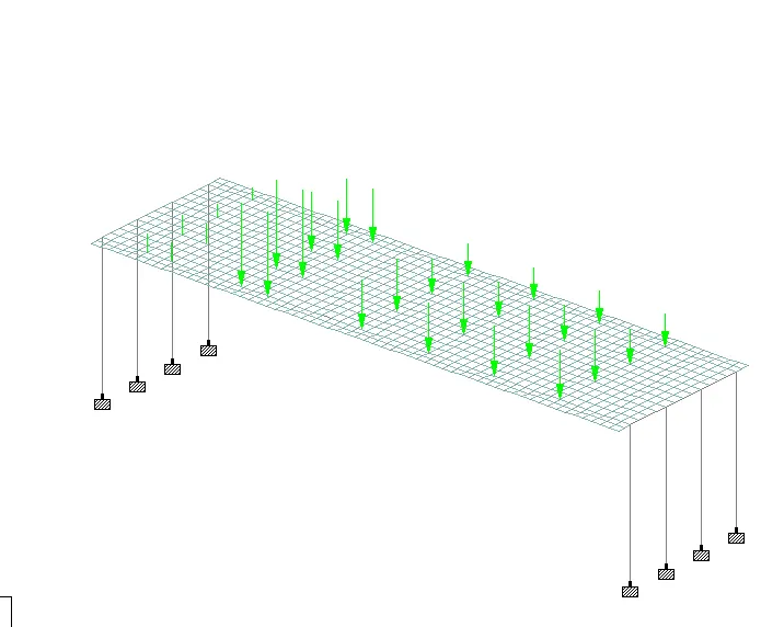
(Moving Load diagram)
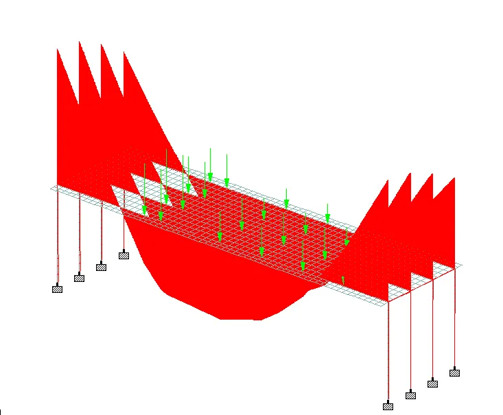
(Bending Moment Diagram)
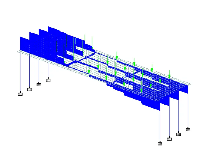
(Shear Force Diagram)
Summary:
Cross Girder:
Maximum Positive Bending Moment: 9.343 kN.m
Maximum Negative Bending Moment: 69.598 kN.m
Maximum shear force: 28.988 kN
Main girder:
Maximum Positive Bending Moment: 832.257 kN.m
Maximum Negative Bending Moment: 574.184 kN.m
Maximum shear force: 271.327 kN
Pier:
Maximum Bending Moment: 836.218 kN.m
Maximum axial force: 278.29 kN
iii) IRC 70R load,
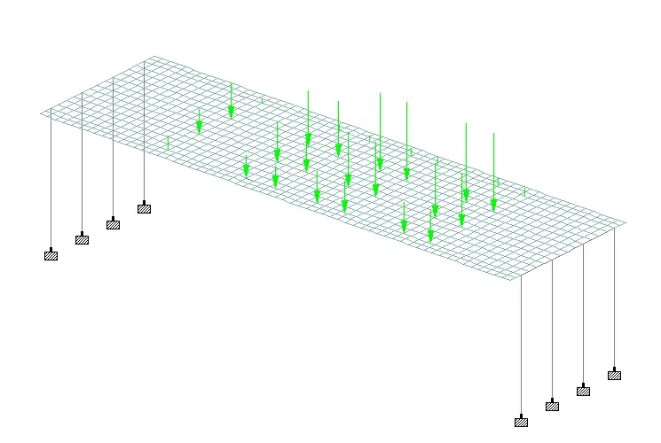
(Moving Load diagram)
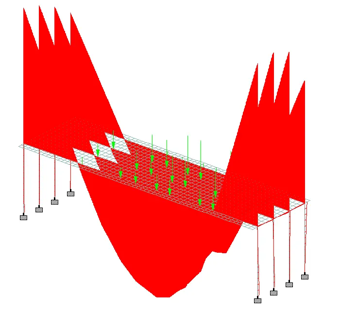
(Bending Moment Diagram)
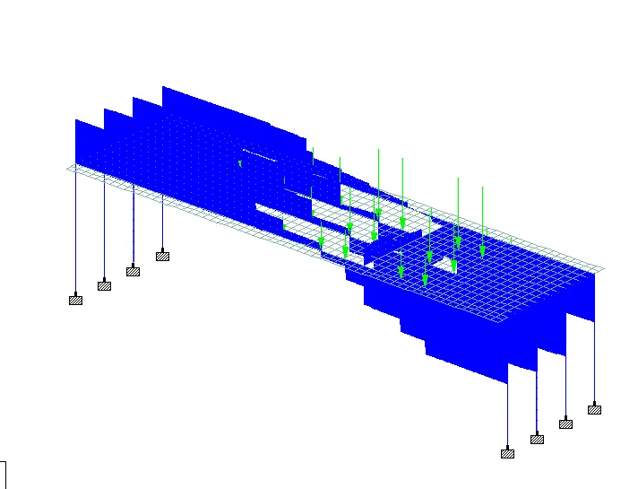
(Shear Force Diagram)
Summary:
Cross Girder:
Maximum Positive Bending Moment: 21.119 kN.m
Maximum Negative Bending Moment: 289.771kN.m
Maximum shear force: 155.939 kN
Main girder:
Maximum Positive Bending Moment: 1442.5 kN.m
Maximum Negative Bending Moment: 1032.325 kN.m
Maximum shear force: 520.041 kN
Pier:
Maximum Bending Moment: 1453.507 kN.m
Maximum axial force: 509.335 kN
Note: Staad file also has been attached.