Week 6 Challenge
Aim: To calculate the pipe loads and apply them on the bridge and do the structural analysis.
Given data:
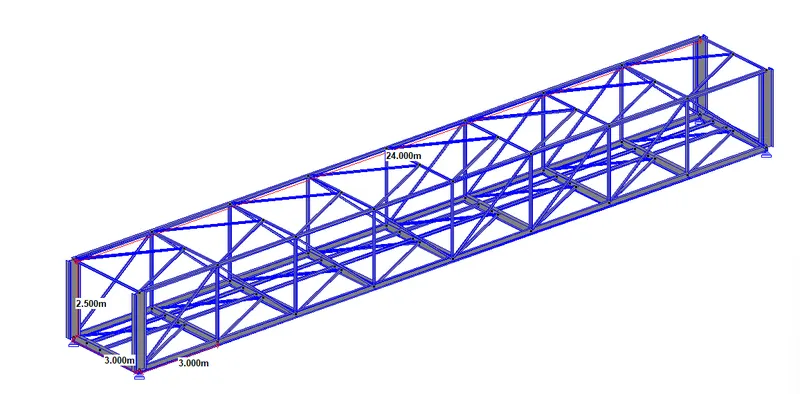
The length and width of the bridge are 24 m & 3 m respectively.
The bridge is carrying two DI K9 pipes having NB of 700 mm & 200 mm respectively.
Solution:
Calculation of pipe load,
For the dead weight of the pipe,
Unit weight of steel =78.5 kN/m3, the Unit weight of mortar =24 kN/m3, and the Unit weight of water =10 kN/m3.
for 700 NB DI pipe,
thk of DI k9 pipe =10.8 mm as per table 2 of IS 8329.
Lining thickness considered = 6 mm as per table 15 of IS 8329.
load per meter length = π x (0.7+(10.8/1000))* (10.8/1000) *1 *78.5 + π x (0.7+2*(10.8/1000)+(6/1000))* (6/1000) *1 *24 =1.89 +0.33 =2.22 kN/m
for 200 NB DI pipe,
thk of DI k9 pipe =6.3 mm as per table 2 of IS 8329.
Lining thickness considered = 3 mm as per table 15 of IS 8329.
load per meter length = π x (0.2+(6.3/1000))* (6.3/1000) *1 *78.5 + π x (0.2+2*(6.3/1000)+(3/1000))* (3/1000) *1 *24 =0.32 + 0.05 =0.37 kN/m
Weight of water inside the pipe,
For 700 NB DI pipe,
water load per meter length = (π/4) x 0.7^2 x 1 x 10 = 3.84 kN/m
For 200 NB DI pipe,
water load per meter length = (π/4) x 0.2^2 x 1 x 10 = 0.32 kN/m
Point load to be applied on staad pro,
Length between cross girders of the bridge = 3 m
For 700 NB pipe,
So reaction due to the dead weight on the middle cross girders= (1.5+1.5) x 2.22 =6.66 kN ( Due to contribution of 1.5 length each of pipe on both the side)
reaction due to the dead weight on the end cross girders= 6.66/2 =3.33 kN (Due to contribution of pipe of 1.5 length of pipe on one side)
So reaction due to the water weight on the middle cross girders= (1.5+1.5) x 3.84 =11.52 kN ( Due to contribution of 1.5 length each of pipe on both the side)
reaction due to the water weight on the end cross girders= 11.52/2 =5.76 kN (Due to contribution of pipe of 1.5 length of pipe on one side)
For 200 NB pipe,
So reaction due to the dead weight on the middle girders= (1.5+1.5) x 0.37 =1.11 kN ( Due to contribution of 1.5 length each of pipe on both the side)
reaction due to the dead weight on the end girders= 1.11/2 =0.55 kN (Due to contribution of pipe of 1.5 length of pipe on one side)
So reaction due to the water weight on the middle girders= (1.5+1.5) x 0.32 =0.96 kN ( Due to contribution of 1.5 length each of pipe on both the side)
reaction due to the water weight on the end girders= 0.96/2 =0.48 kN (Due to contribution of pipe of 1.5 length of pipe on one side)
Modeling of the bridge in staad pro & load application,
As per the given data,
Staad model was prepared.
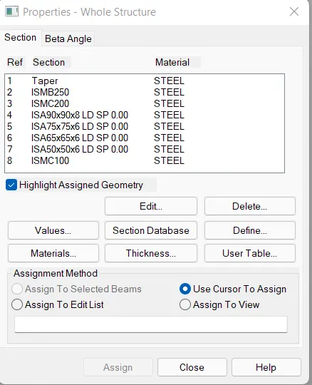
Properties for the different members were also assigned accordingly,
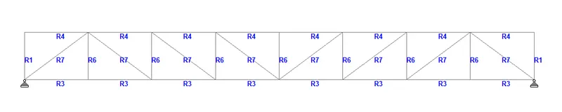
(Longitudinal Cross-section of the bridge)
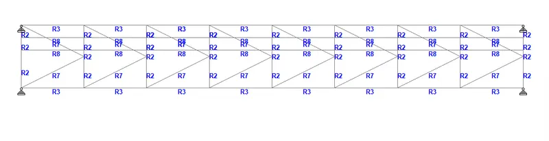
(View at Bottom Girder level)
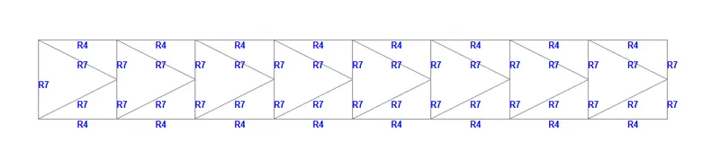
(View at Top Girder level)
Simply support condition has been considered at both ends of the bridge.
Application of load,
As it can be seen from the input, 700 NB DI pipe is supported on the cross girder at 1 m from the right end and 200 NB DI pipe is supported on the cross girder at 1.64 m from the right end. According to this, the point loads calculated above is applied on staad pro.
Two load cases are added naming dead load and live load.
In the dead load case, the self-weight of different members of the bridge along with dead weight due to the pipe is considered.
In the live load case, water load inside the pipe is considered and applied on the cross girder as point loads.
A load combination has been created with 1 as a factor for both dead & live load to see the effect of both dead and live load.
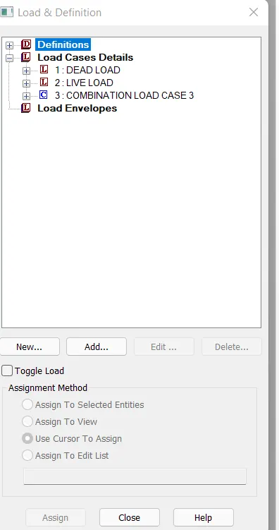
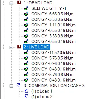
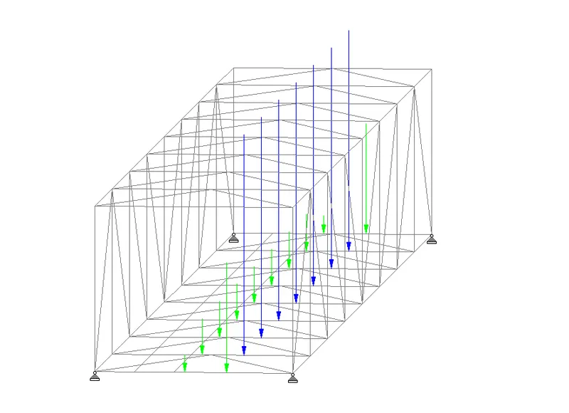
(Image Showing application of dead load)
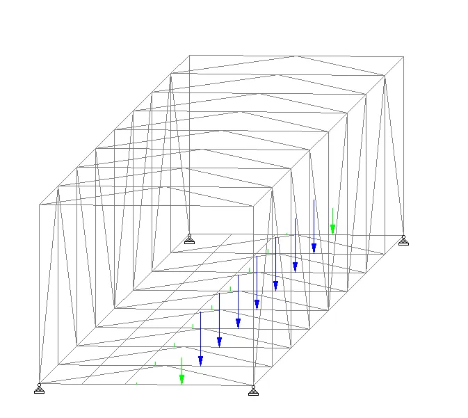
(Image Showing application of Live load)
Results:
> All the results shown below are for the load combination case(DL+LL).
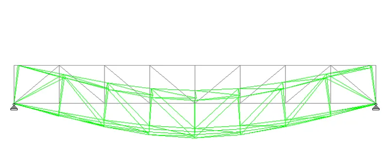
(Deflection Profile)
The details of the internal force encountered by different important members of the bridge are summarised below.
Cross Girder:
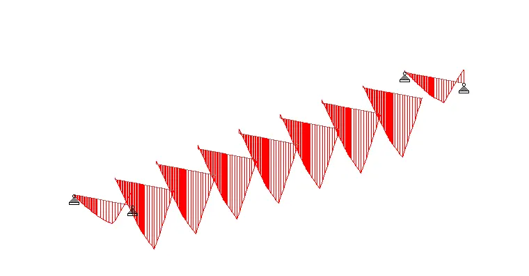
( Bending Moment diagram)
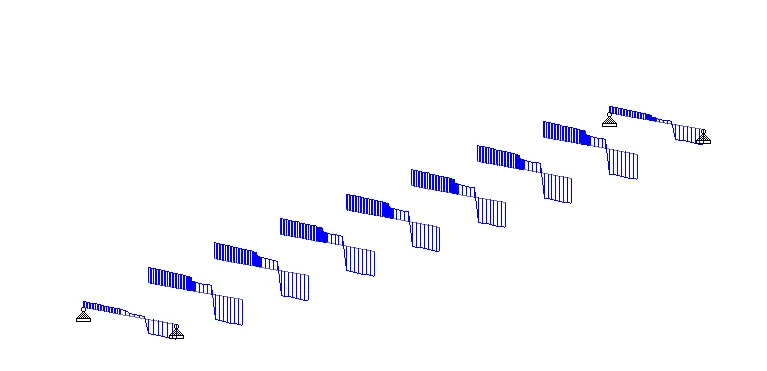
(Shear Force Diagram)
Maximum bending moment observed = 13.518 kN.m
Maximum shear force observed = 13.852 kN
Bottom Chord:
Maximum Axial force observed = 42.311 kN.
Diagonal Member:
Maximum Axial force observed = 85.838 kN.
Vertical Member:
Maximum Axial force observed = 25.180 kN.
Top Chord:
Maximum Axial force observed = 149.614 kN.
Bottom Bracing:
Maximum Axial force observed = 3.782 kN.
Top Bracing:
Maximum Axial force observed = 1.807 kN.