Week 7 Challenge
Please find the attached Staad model for your review.
Q1.Aim :
To model the structure with given input using staad pro.
Given Data:
- Bay spacing 5 m
- Span of Truss 30 m
- Shape of Truss – Pratt Truss
- Slope of truss 20 degree
- Height of the column 15 m
- Floor Beams at 5 m from base
- Secondary beams at 1.5 c/c
- Length of the building 50 m
- Column Supporting Floor Beam @ 6 m c/c Along the frame.
Solution:
Kindly note, all dimensions mentioned below are in meter.
- Firstly, In the nodes table, consider three nodes in xy plane i.e 1st(0,0,0),2nd(30,0,0) and 3rd(15,0,0).
- To make the roof truss having an angle of 20 degrees, The height of the mid vertical member which starts at node (15,0,0) of the truss is chosen to be (30/2)*tan(20) which is equal to 5.46 m.
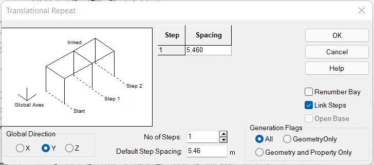
- Now with the help of the translation repeat option in the geometry tab, with global direction as Y and default spacing as 5.46 m, no of steps as 1 and tick in link steps, the middle vertical member is modelled and 4th node( 15,5.46,0) is created.
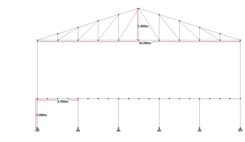
- Now by using add beam option, beam elements between 1st and 3rd node , 3rd and 2nd node are created and that beam is then discretized by the help of insert node option in geometry tab such that starting node of each vertical of the truss with a horizontal spacing of 3 m will be created.and all bottom chords members are also created accordingly.

- Then for top chord, 1st - 4th node and 2nd -4th node are joined by add beam option.
- Then from each discretized point of the bottom chord, vertical members will be created and will be joined with the top chord member.
- Accordingly, diagonals are also created according to pratt type truss.
- Then for the external column,1st and 2nd nodes are selected and by use of translation repeat option with link steps, external columns are created.
- Floor beams at 5 m from the bottom of the column and internal columns at 6m c/c spacing were also created.
- Nodes for secondary beams at c/c spacing of 1.5 m is also created such that for a distance of 6 m length of floor beam, 3 secondary beams will connect with it.
- Single Bay can be viewed like this.
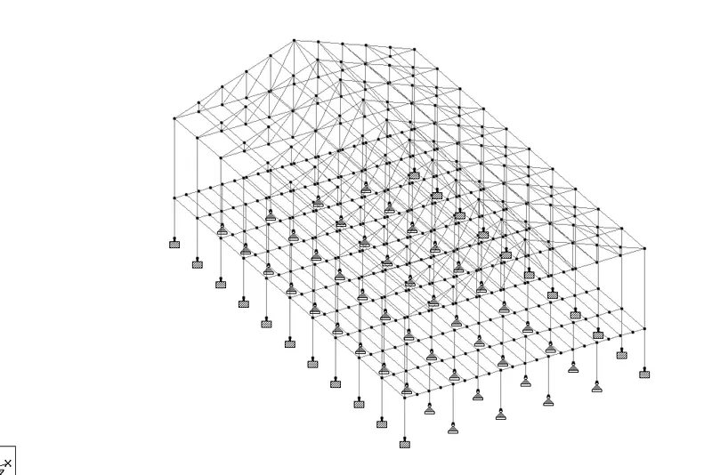
- Now select the whole bay and use translation repeat option in Z-direction with spacing as 5 m for 10 steps and ticked in link steps option, Whole structure will be created.
- It can be viewed as shown below.
Resut:
According to the steps mentioned above, the staad model is prepared.
Q2.
Aim:
To apply beam steel specification as mentioned below
Given Data:
- Columns - ISMB 500
- Truss -Top & Bottom chord – ISA 110x110x12, Diagonal member – ISA 75x75x8
- Purlins – ISMC 150
- Tie Beam – ISA 120x120x10
- Floor Primary beams – ISMB 300
- Secondary beams - ISMC 150
- Floor beam supporting columns – ISMB 300
- Assume bottom of the main column as Fixed support & intermediate floor beam supporting column as pinned
- Orient the Angle sections by applying Beta angle.
Solution:
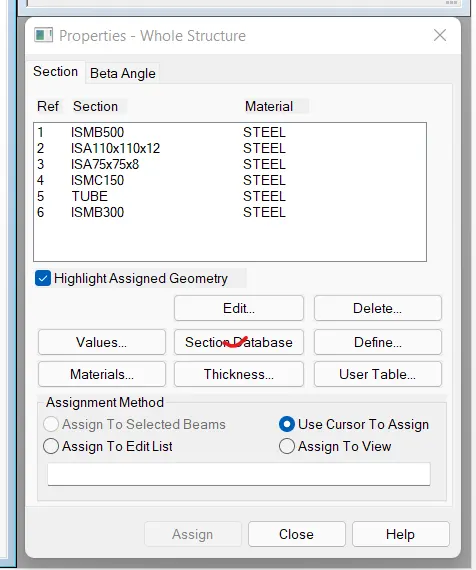
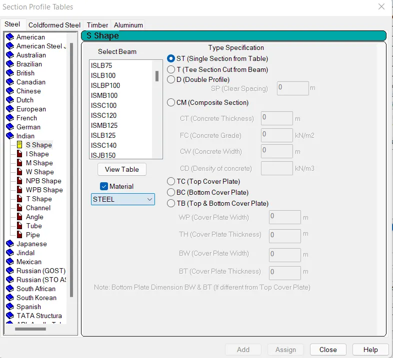
- >To assign steel properties,Go to properties tab, in section tab, choose section data base and select indian section and add section as per requirement.
>Then click on the properties added and select the members in which the properties needs to be assigned and then click assign to selected beams in the properties dialog.
2.To assign different support type to selected nodes,
>Create different type of support by clicking on create option in support tab and then add support types like fixed or pinned and click add.
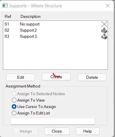
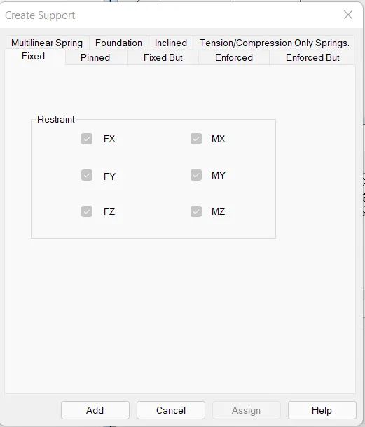
>Then select the support type and select the nodes which will be assigned with support and click on assign to selected nodes .
3.To assign beta angle to members,
>Go to properties tab and choose beta angle option, then click on create beta angle and choose angle in degrees and write the angle to be added and click on OK.
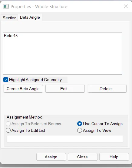
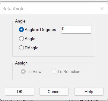
> Then click on the beta angle and select the member in which the beta angle is to be added and click on assign to selected beams.
Result:
According to the procedure given above, the given section properties, beta angle and support details are added in the staad model.
Q3.
Aim:
Creating a group for different members.
Given data:
To form group for following members
- External column
- Internal columns
- Roof Frames
- Top chord of the Truss
- Primary Beams
- Secondary Beams
Solution:
To create a group of members,
>Go to utilites, the choose groups.
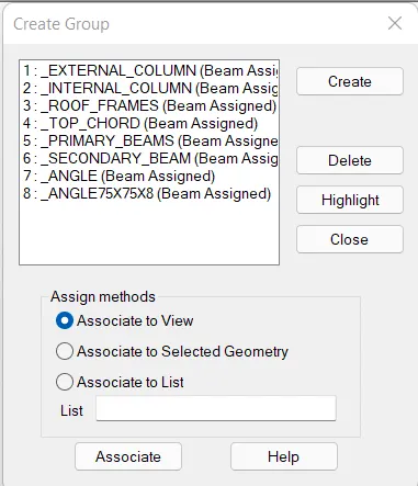
>Click on create. select beam as type and put group name and press ok.
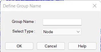
>Then select the members to be added in one group and choose the group name from list of groups and click on assign to selected geometry.
Result:
By following the steps mentioned above, groups for different members are prepared.