Study of different DC Motor Control systems
Aim: To study and analyze different DC motor control systems.
Objective:
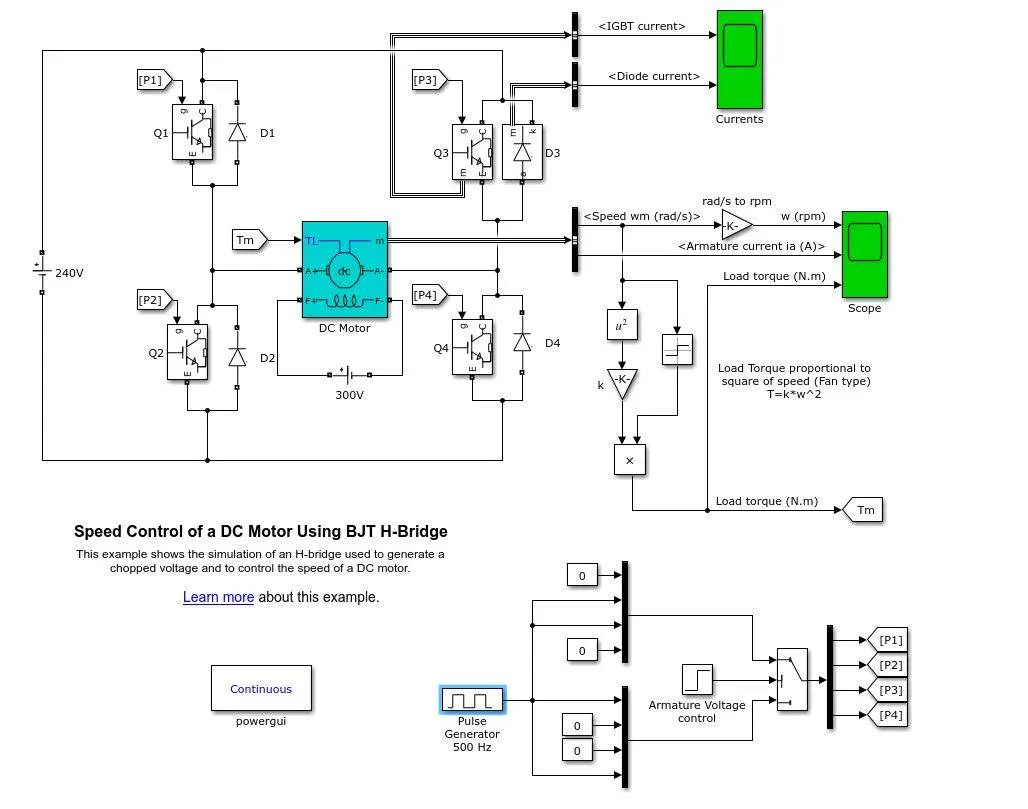
- Run MATLAB demo, Speed control of a DC motor using BJT H-bridge. Modify the model such that the armature current doesn’t shoot up when the motor changes direction from forward to reverse.
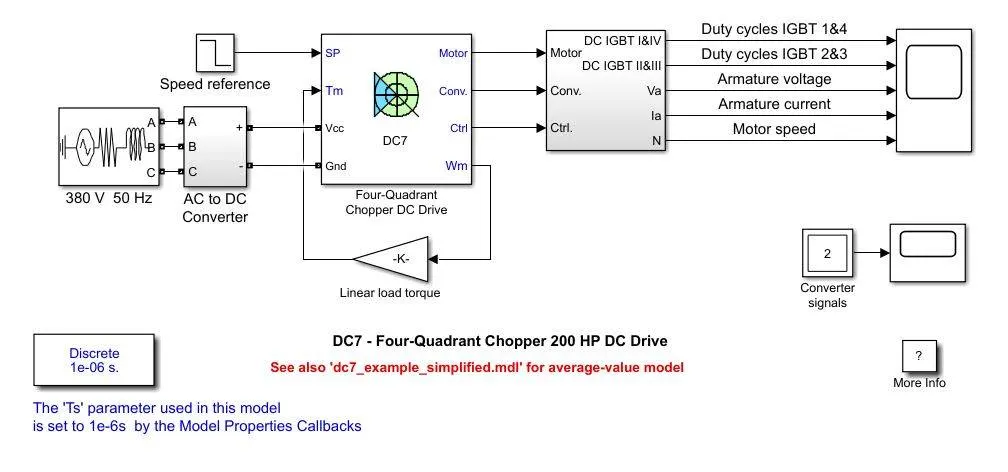
- Refer to the help section of, The Four-Quadrant Chopper DC Drive (DC7) block. Compare it with the H-bridge model.
- Make a suitable EV model using the DC7 block and make a result report.
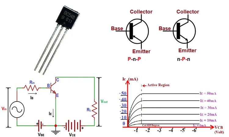
1) BJT:
- A bipolar junction transistor (BJT) is a type of transistor that uses both electrons and holes as charge carriers.
- Unipolar transistors, such as a field-effect transistor, use only one kind of charge carrier.
- A bipolar transistor allows a small current injected at one of its terminals to control a much larger current flowing between two other terminals, making the device capable of amplification or switching.
- BJTs use two junctions between two semiconductor types, n-type and p-type, which are regions in a single crystal of material.
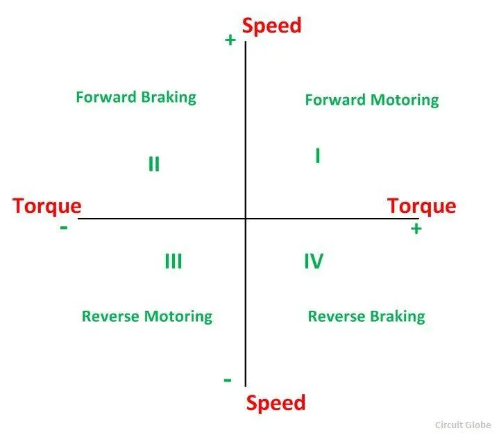
Speed vs Torque all four quadrants:
Speed control model of a DC motor using BJT H-bridge in Simulink:
Simulation:
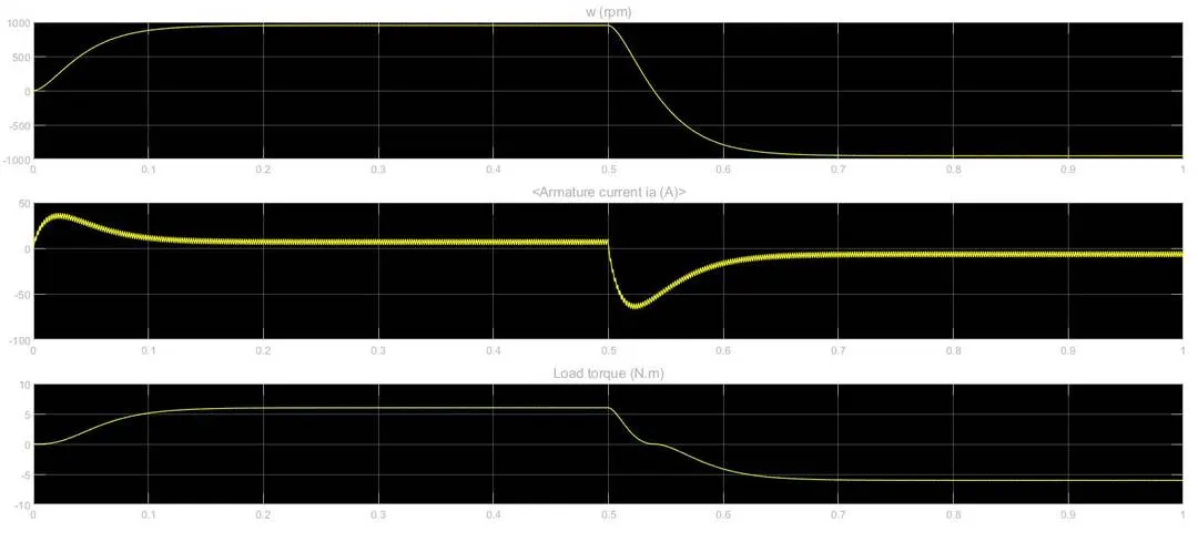
(i) Initially, the motor starts in a positive direction with a duty cycle of 75% (mean DC voltage of 180V)
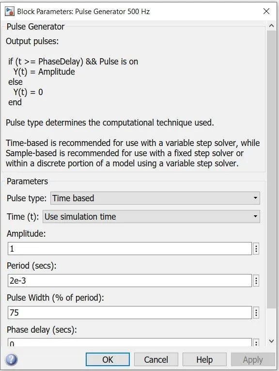
- At t= 0.5 sec., the armature voltage is suddenly reversed and the motor runs in the negative direction. The scope shows motor speed, armature current, and load torque and Currents shows currents flowing in BJT Q3 and diode D3.
(ii) The motor starts in a positive direction with a duty cycle of 50% (mean DC voltage of 120V).
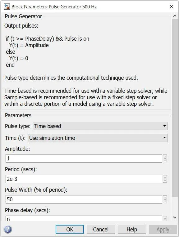
- At t= 0.5 sec., the armature voltage is suddenly reversed and the motor runs in the negative direction. The scope shows motor speed, armature current, and load torque and Currents shows currents flowing in BJT Q3 and diode D3.
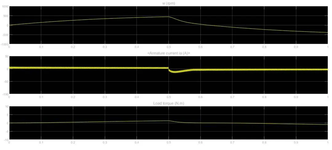
(iii) The motor starts in a positive direction with a duty cycle of 45% (mean DC voltage of 108V).
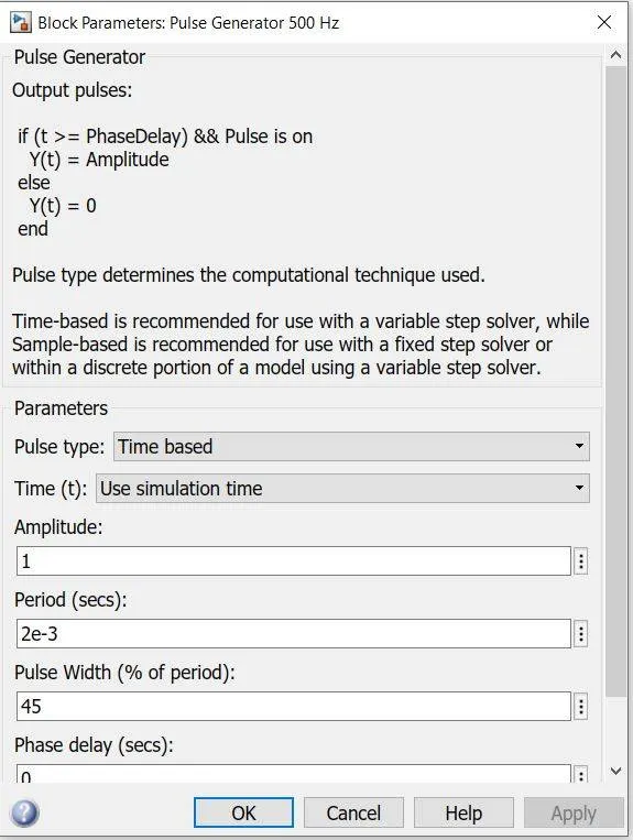
- At t= 0.5 sec., the armature voltage is suddenly reversed and the motor runs in the negative direction. The scope shows motor speed, armature current, and load torque and Currents shows currents flowing in BJT Q3 and diode D3. Here armature current does not shoot up when the motor changes its direction.
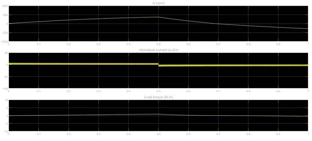
(iv) The motor starts in a positive direction with a duty cycle of 25% (mean DC voltage of 60V).
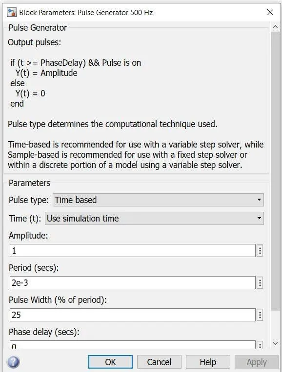
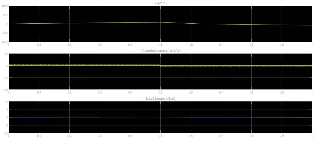
- At t= 0.5 sec., the armature voltage is suddenly reversed and the motor runs in the negative direction. The scope shows motor speed, armature current, and load torque and Currents shows currents flowing in BJT Q3 and diode D3.
*Here current does not shoot up when the motor changes its direction but torque becomes 0.
2) The Four-Quadrant Chopper DC Drive (DC7) block:
H-Bridge:
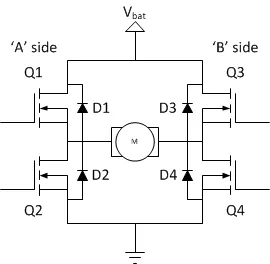
- An H-bridge is an electronic circuit that switches the polarity of a voltage applied to a load.
- These circuits are often used in robotics and other applications to allow DC motors to run forwards or backward.
H-Bridge Circuit:
Working:
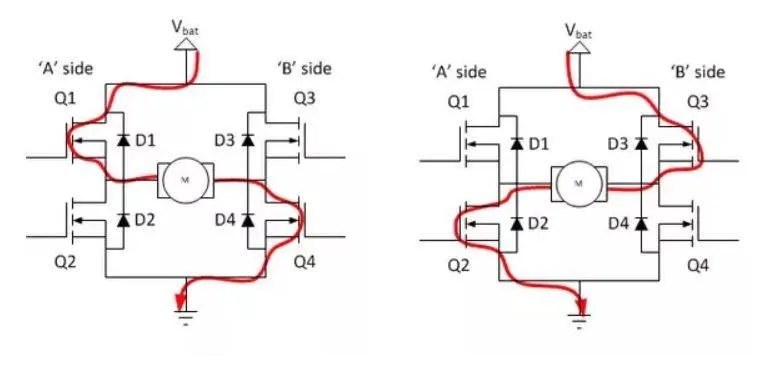
- An H bridge is built with four switches.
- When the switches D1 and D4 (according to the first figure) are closed (and D2 and D3 are open) a positive voltage will be applied across the motor.
- By opening D1 and D4 switches and closing D2 and D3 switches, this voltage is reversed, allowing reverse operation of the motor.
H-Bridge block:
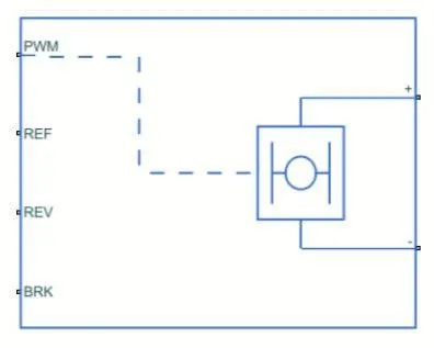
Using this H-Bridge block a DC motor control model is below:
PWM-Controlled DC Motor:
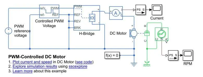
- This model shows how to use the Controlled PWM Voltage and H-Bridge blocks to control a motor.
- The DC Motor block uses manufacturer datasheet parameters, which specify the motor as delivering 10W mechanical power at 2500 rpm and no-load speed as 4000 rpm when run from a 12V DC supply.
- Hence if the PWM reference voltage is set to its maximum value of +5V, then the motor should run at 4000rpm, If it is set to +2.5V, then it should run at approximately 2000 rpm.
- The Simulation model parameter is set to Averaged for both the Controlled PWM Voltage and H-Bridge blocks, resulting in fast simulation.
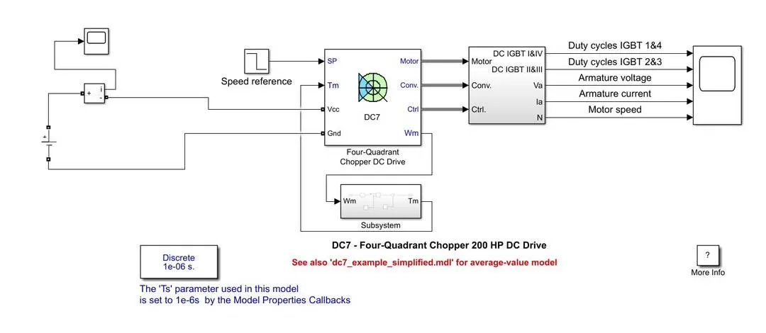
3 To make a suitable EV model using DC7 block:
Remove:
- 380V 50Hz AC power source
- AC to DC converter
- Linear load torque
- Converter signal block with scope
Add:
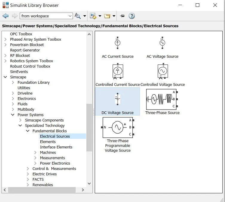
(i) A DC Voltage source in place of an AC power source
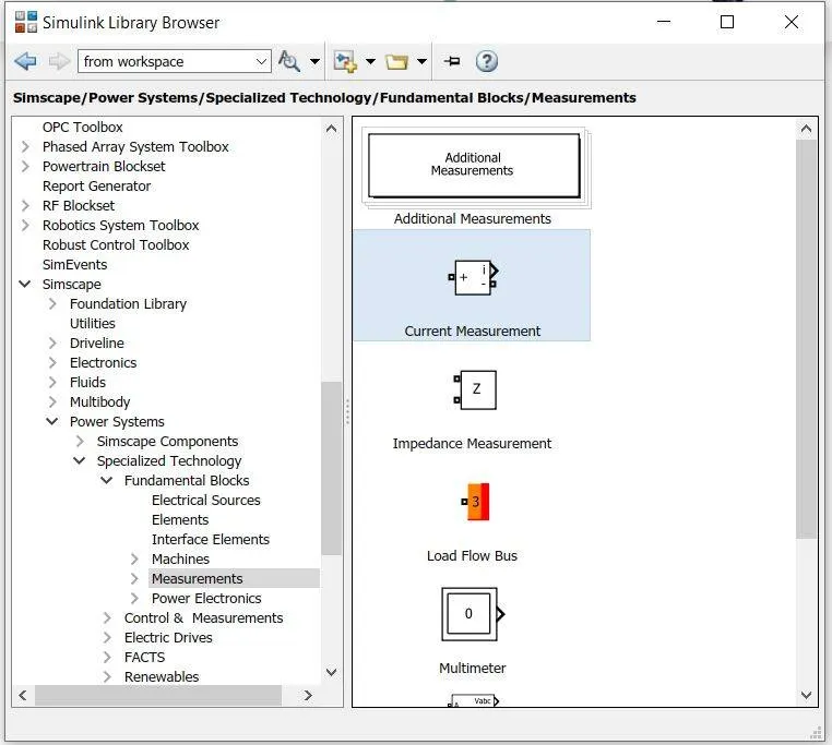
(ii) A Current sensor in series with DC Voltage source's positive terminal
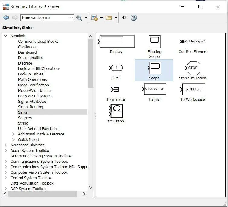
(iii) A Scope with the current sensor
(iv) We have to give a torque-speed relation that is Tm=24.7+0.0051Wm^2.
- For this, we need to build a subsystem using the mathematical operations of Simulink.
*We will replace the Linear load torque with this subsystem
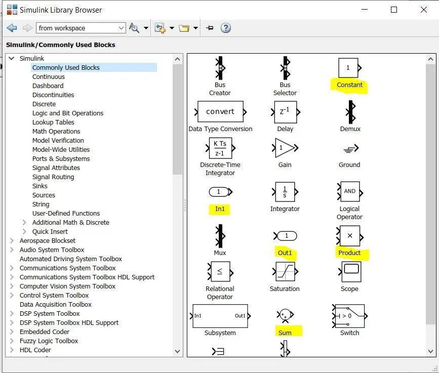
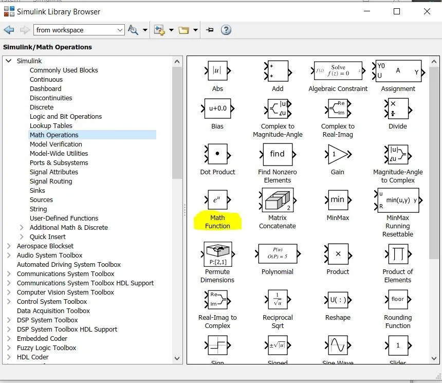
- Using these blocks we will make a subsystem that is given below
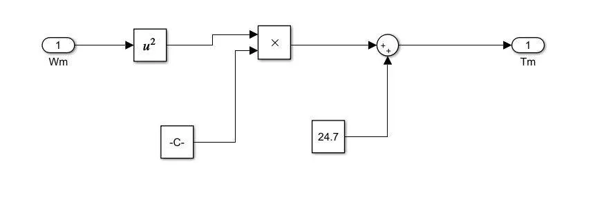
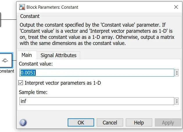
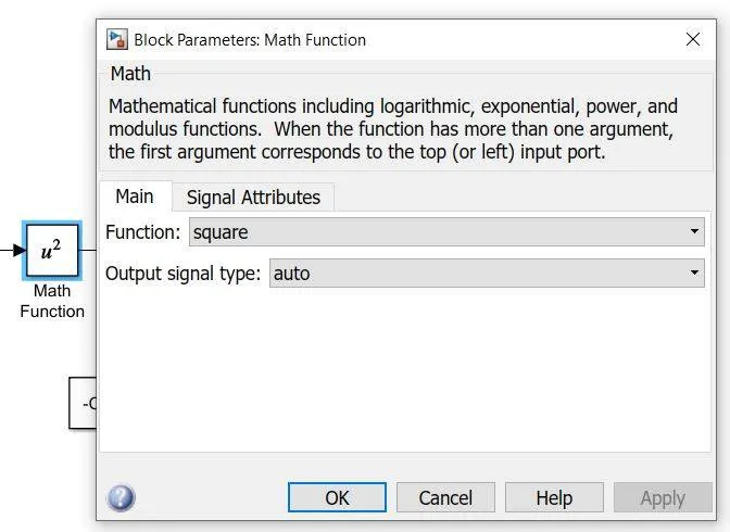
- And keeping all other parameters as default finally we will make a suitable vehicle model using the DC7 block that is given below
Result report:
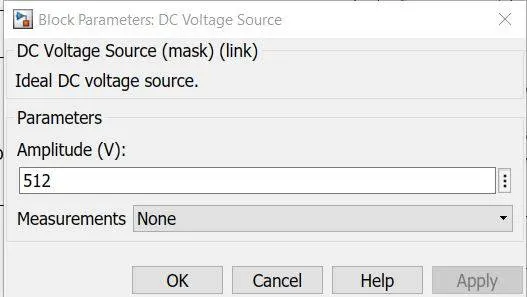
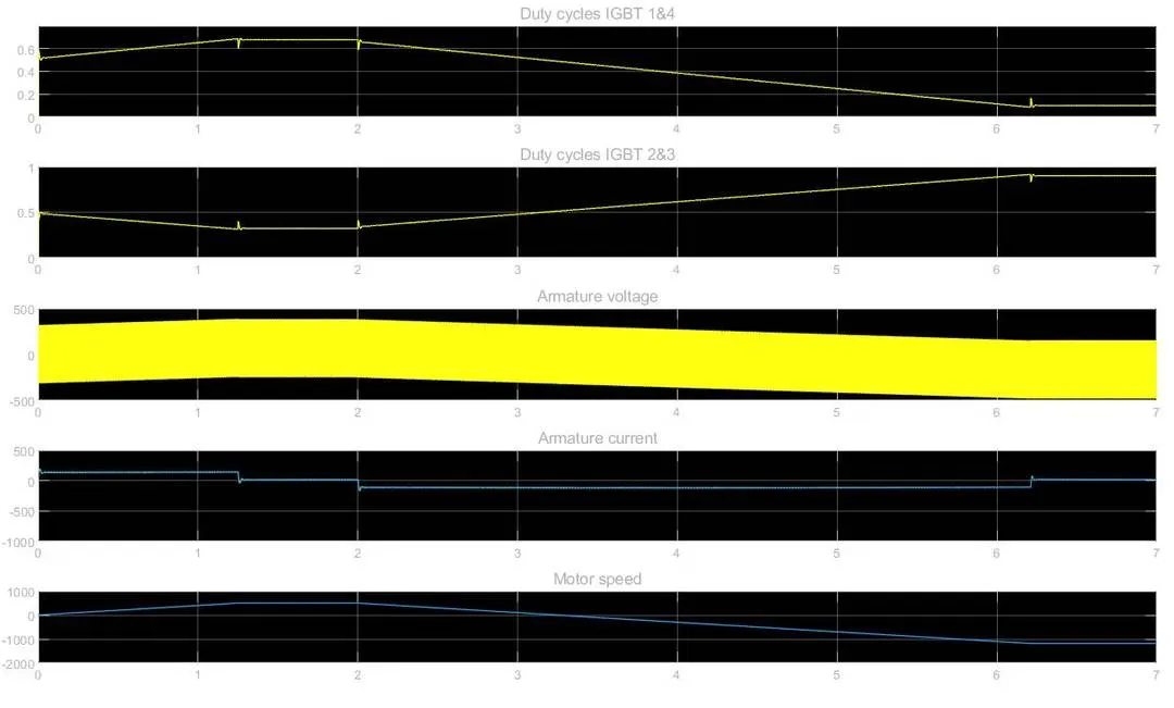
a) At voltage amplitude of 512V:
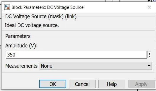
b) At voltage amplitude of 350V:
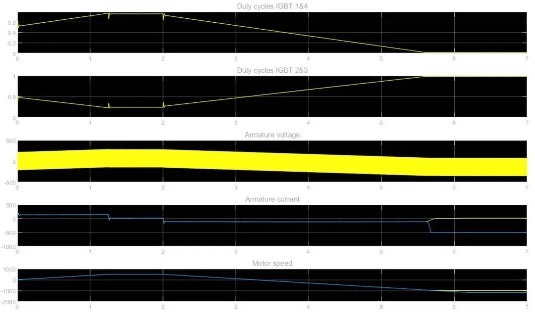
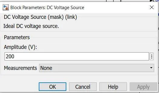
c) At voltage amplitude of 200V:
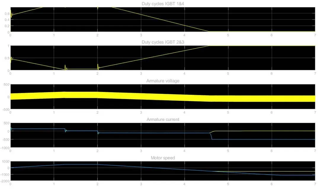
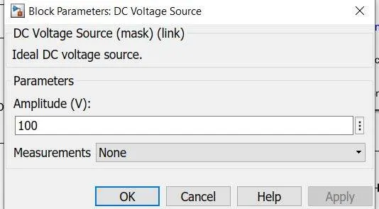
d) At voltage amplitude of 100V:
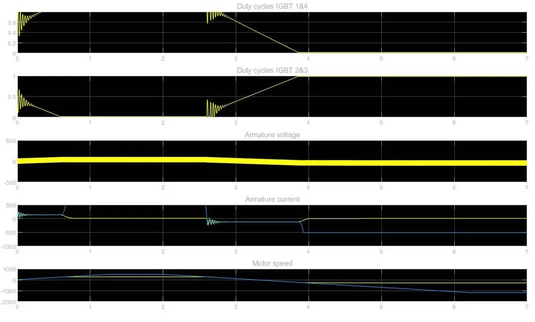
*It is evident that motor speed trying to match the target speed.
References:
- https://skill-lync.com/projects/multi-quadrant-operation-of-dc-motor-in-simulink
- https://in.mathworks.com/help/physmod/sps/ug/speed-control-of-a-dc-motor-using-bjt-h-bridge.html?s_tid=srchtitle
- https://in.mathworks.com/help/physmod/sps/ug/dc7-four-quadrant-chopper-200-hp-dc-drive.html?s_tid=srchtitle
- https://in.mathworks.com/help/physmod/sps/ug/pwm-controlled-dc-motor.html?s_tid=srchtitle
- https://circuitglobe.com/four-quadrant-operation-of-dc-motor.html#:~:text=Both%20the%20speed%20and%20the,in%20the%20reverse%20motoring%20mode.