Induction Motor Characteristics
1) How induction motor operation is similar to the clutch?
Working of Clutch:
- In a manual transmission car, a clutch is a component that is needed to change the gear to transition from one-speed range to another in a smooth manner. When the driver wants to change the gear in order to achieve a higher or lower speed, the driver has to first press the clutch pedal and make the gear transition while the clutch is pressed down. Once the gear change has taken place, the clutch can be released and the vehicle can continue to operate at the new speed range.
- In manual transmission vehicles, to make a smooth gear change means to discontinue the power flow from the engine to the transmission. But it is not practical to switch off the engine for the purpose of a gear change while the vehicle is running. So, a clutch solves this issue as it can discontinue the engine power flow to the transmission without turning off the engine.
- The main part of a clutch consists of a disc that is coated with high friction material on either side and it is connected to the engine flywheel. If an external force acts on the clutch disc, the flywheel will also turn the flywheel due to friction. So, when an external force is applied to the clutch disc, it will get transmitted to the transmission system. This external force is provided by a pressure plate system, the cover of which is fixed firmly to the flywheel.
- But for power disengagement, a diaphragm spring is used and it is housed between the pressure plate and its cover. The outer portion of the diaphragm spring is connected to the pressure disc. When the clutch is pressed, a hydraulic system converts the clutch motion to the center of the diaphragm spring. If an external force acts on the center of the diaphragm spring, the pressure disc will move away from the friction disc and discontinue the power flow to the transmission. When the clutch pedal is released, the power flow continues flowing to the transmission.
Induction Motor & Clutch:
- So, the clutch is used to engage and disengage the power transmission from the driving shaft to the driven shaft. The driven shaft i.e. disc is located between the engine and the pressure plate. When the clutch is engaged, the driven disc is pressed against the flywheel transferring the torque from the engine to the transmission. The driving disc i.e. clutch cover is rigidly bolted to the engine. When the clutch is engaged, its inner part will press the pressure disc which in turn presses the driven disc to the flywheel. The 2 shafts are rotating at different speeds which causes a slip and clutch attempts to lock them together or release them. The slip that exists between the driving and driven shafts is given by:
`omega2=omega1(1-s)`
where,
driving shaft speed = `omega1`
driven shaft speed = `omega2`
slip = `s`
- The operation of a clutch is similar to that of an induction motor in terms of the slip. In an induction motor, there is a slip that occurs between the speed of the rotating magnetic field i.e. the synchronous speed and the speed of the rotor. This slip is essential for the working of the induction motor because it is the rotating magnetic field that exerts an electromagnetic force on the rotor causing it to rotate, producing a torque. This creates a small phase difference between the two. If they were rotating at the same speed, there would be no excitation of the rotor as there would be no interaction between the rotating magnetic field and the rotor. So, the speed of the rotating magnetic field i.e. synchronous speed is always greater than the speed of the rotor. Slip is defined mathematically with the equation below.
`Slip, s = (Ns-Nr)/(Ns)`
where,
Synchronous speed = `Ns`
Rotor speed = `Nr`
slip = `s`
This can be written as,
`Nr=Ns(1-s)`
From this, we can see that the clutch and the induction motor have some similarities in their operation.
2) Calculate the starting time of a drive with the following parameters:
- J=10 kg-m2,
- T = 15 + 0.5wm
- Tl=5+0.6ωm
To find the steady-state speed, we need to equate the load torque and motor torque equations:
Given:
- J=10 kg-m2,
- T = 15 + 0.5wm
- Tl=5+0.6ωm
MATLAB Code:
clear all
close all
clc
t_p = [0 300];
i_c = [0 0];
[t w] = ode45(@functionomega, t_p, i_c);
plot (t,w)
title('w-dot (dw/ dt)');
xlabel('time(sec)');
ylabel('omega (rad /sec)');
grid on
Function Code:
function [w_dot] = functionomega(t,w)
w_dot = 1-0.01*(w);
end
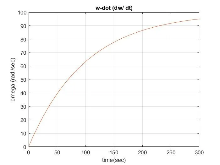
Output Graph:
`Tm=Tl`
`15+(0.5*omegam)=5+(0.6*omegam)`
`0.1*omegam=100`
`omegam=100`rad/s..........steady state speed
Therefore,
`15+0.5*omegam=5+0.6*omegam*(domegam)/dt`
`(domegam)/dt=(10-0.1*omegam)/10`
`1-0.01*omegam`
`dt=(1)/(1-0.01*omegam)*domegam`
Now, integrating above eqn w.r.to time (t),
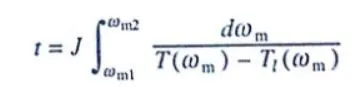
The integral limits should be considered from the initial condition of the motor to the end of the transit state after which the motor attains its steady speed. So we consider steady speed. So we consider Wm1 = 0 & Wm2 = 95% of Wm.
`omega m =100`rad/s
`omegam1=0`rad/s
`omegam2=95`rad/s
Therefore,
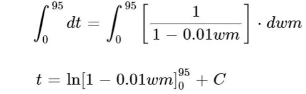
when t=0, Wm=0
C=0
Applying integral limits,
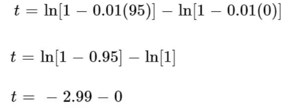
Therefore, starting time for a given induction motor is t=3s
3) A drive has the following equations for motor and load torques:
- Tm=(1+2ωm)
- Tl= 3 √ωm
Obtain the equilibrium points and determine the stability
To find the equilibrium points and the stability of the drive, we need to first equate the equations of the motor and load torques.
Motor torque:`Tm=1+(2*omegam)`
Load torque: `Tl=3*sqrtomegam`
on equating, we get
`1+(2*omegam)=3*sqrtomegam`
squaring on both sides,
`4*(omegam)^2-(5*omegam)+1=0`
solving,
`omegam=0.25`
`omegam=1`
This is verified by a MATLAB program I created which plots the curves of both motor and load's torque-speed characteristics.
MATLAB Code:
clear all
close all
clc


% Motor Speed Array

x = linspace(0, 5, 20);


% Motor Torque

y1 = 1 + 2*x;


% Load Torque

y2 = 3*(x.^0.5);


% Plotting

plot(x, y1, 'linewidth', 2)
hold on
plot(x, y2, 'linewidth', 2)
title('Speed Vs. Torque characteristics')
xlabel('Speed, rpm')
ylabel('Torque, Nm')
legend('Motor Torque', 'Load Torque')
Output Graph:
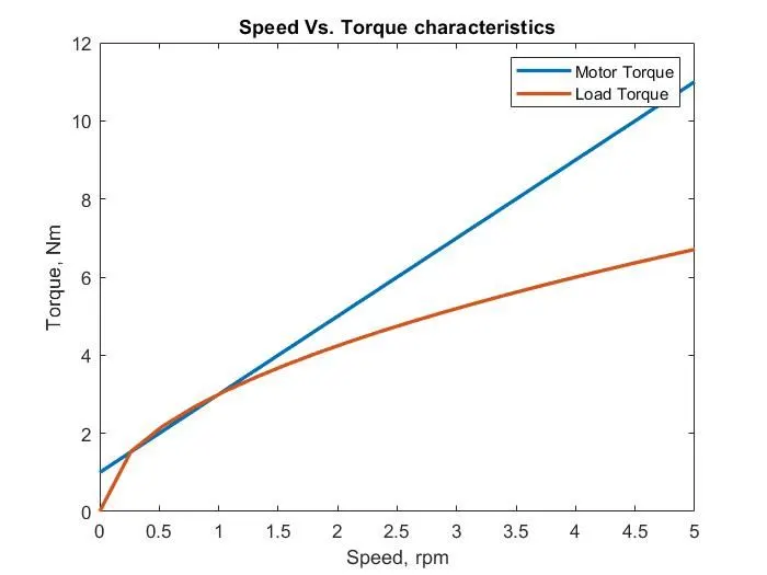
As we can see from the graph, the 2 curves intersect at 2 points which means there are 2 solutions. The 2 curves intersect exactly at x=0.25rad/s and x=1rad/s.
Now that we have the 2 equilibrium points, we need to determine at what speed the drive is stable.
The stability condition is,
`(dTl)/(domegam)-(dTm)/(domegam)>0`
- In other words, if the difference between the differential equations of the load and torque is greater than 0, the condition is satisfied.
- If this condition is satisfied for the given equilibrium points, then it means that the induction motor is stable to operate at those speeds.
- To use this condition, we need to find the differences between the load torque and motor torque equations with respect to the angular speed.
First, we will differentiate the load torque equation:
`(dTl)/(domegam)=3*0.5*omegam^(0.5-1)`
`(dTl)/(domegam)=3/2*omegam^-0.5`
on differentiating, we get
`(dTl)/(domegam)=2`
The differential of the motor torque equation is just a constant, 2.
Therefore, the stability eqn for this is:
`(3/2*(omegam)^-0.5)-2>0`
For this equation, we will substitute the 2 equilibrium points and check if the condition is satisfied.
- For `omegam=0.25`
`=3/2*(0.25)^-0.5-2`
`=3`
So, when the angular speed is 0.25 rad/s, the stability condition is satisfied, because the difference in the differential between the motor and the load torque is greater than 0. Now we can check when the angular speed is 1.
- For `omegam=1`
`=3/2*1^-0.5-2`
`=1.5-2`
`=-0.5`
So when the angular speed is 1 rad/s, the stability condition is not satisfied, because the difference in the differential between the motor and the load torque is lesser than 0.
So, the Induction Motor drive is only stable at 0.25rad/s.