Steady Vs Unsteady flow over a cylinder
Steady Vs Unsteady flow over a cylinder
Objective:- Simulate the flow over a cylinder and explain the phenomenon of Karman vortex street.
PART-I
- Simulate the flow with the steady and unsteady case and calculate the Strouhal Number for Re= 100.
PART-II
- Calculate the coefficient of drag and lift over a cylinder by setting the Reynolds number to 10,100,1000,10000 & 100000. (Run with steady solver)
- Discuss the effect of Reynolds number on the coefficient of drag. [ Results should be validated with any standard literature and error should be within 5 %]
Expected results:-
- In both approaches, show that the flow has converged. That is, what quantities or plots need to be looked at to determine that the flow has converged?
- Plots of the coefficient of drag and lift.
- Plots to show vortex shedding behind the cylinder.
- Mention the preferred material at the end of the challenge submission page.
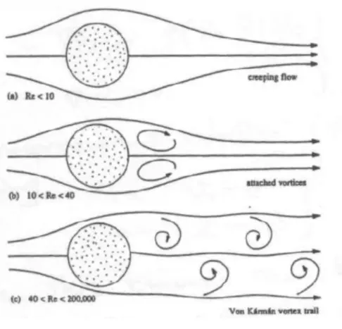
Introduction:- Flow past a blunt body, such as a circular cylinder, usually experiences boundary layer separation and very strong flow oscillations in the wake region behind the body. In certain Reynolds number range, a periodic flow motion will develop in the wake as a result of boundary layer vortice being shed alternatively from either side of the cylinder. This regular pattern of vortices in the wake is called a Karman vortex street. It creates an oscillating flow at a discrete frequency that is correlated to the Reynolds number of the flow. The periodic nature of the vortex shedding phenomenon can sometimes lead to unwanted structural vibrations, especially when the shedding frequency matches one of the resonant frequencies of the structure. The flow over a cylinder found its importance in various practical applications like heat excahangers, in submarines, chimneys etc.
From an engineering standpoint, it is important to predict the frequency of vibrations at
various fluid speeds and thereby avoid undesirable resonances between the vibrations of
the solid structures and the vortex shedding. To help reduce such effects, plant engineers
put a spiral on the upper part of high smokestacks; the resulting variation in shape
prohibits the constructive interference of the vortex elements that the structure sheds from
different positions.
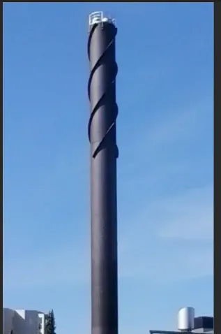
Phenomenon of Karman Vortex street:- It is a repeating pattern of swirling vortices, caused by a process known as vortex shedding, which is responsible for the unsteady separation of flow of a fluid around blunt bodies.
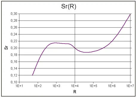
Strouhal Number:- It is a dimensionless number useful for analyzing oscillating unsteady fluid flow dynamics problems. It is expressed as below-

f = vortex shedding frequency.
d = diameter of the cylinder
U = flow velocity.
It is represents a measure of the ratio of interial forces due to unsteadiness of the flow to the inertial forces due to changes in velocity from one point to an other in the flow field.
Strouhal Number is a function of Reynolds number.
Reynolds Number:- It is the ratio of inertial forces to viscous forces within a fluid which is subjected to relative internal movement due to different fluid velocities. It is represent as below-

where:
ρ is the density of the fluid (kg/m3)
u is the flow speed (m/s)
L is a characteristic linear dimension (m) (see the below sections of this article for examples)
μ is the dynamic viscosity of the fluid (Pa·s or N·s/m2 or kg/(m·s))
ν is the kinematic viscosity of the fluid (m2/s).
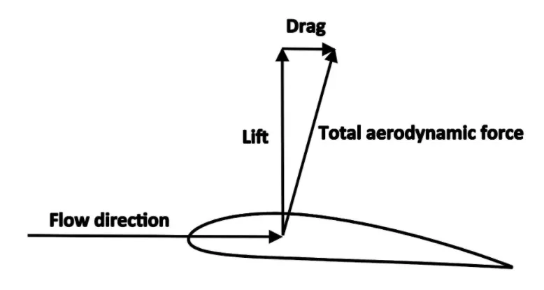
Drag & Lift:- Fluid dynamic forces are due to pressure and viscous forces acting on the body surface.
The component parallel to flow direction, is know as drag & the component normal to flow direction is known as lift.
Work flow of simulation:- Open Ansys workbench, double click/drag drop FLUID FLOW(Fluent) analysis system to project schematic.
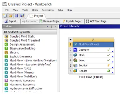
Here we see steps to follow to solve a CFD problem.
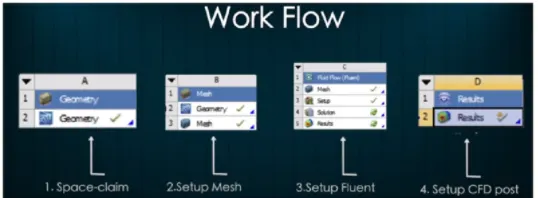
a. Geometry: Spaceclaim, it is used for create gerometry and other CAD related functions.
b. Mesh: used to generate Ansys Mesh and other mesh control option, also assign name which helps during BCs setup.
c. Setup: used to define physics of problem, like BCs, material and type of solving method, iterations etc.
d. Solution: where runtime results visualization done.
e. Results: CFD-Post, where post processing of results will be done.
CAD creation:- I create infinite long cylinder of 2m diameter and computational space 20mx60m a rectangular space. Dimensions shown below-
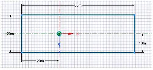
And by pull option we convert this 2D sketch into a solid model.
Mesh generation:-
convert quad mesh to tria mesh & mesh element size is 0.2m.
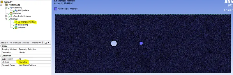
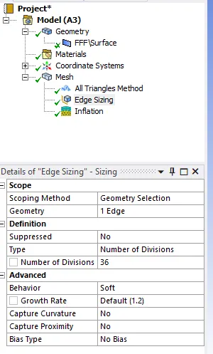
Improve circumference of circle by sizing-> edge sizing. Assign 36 division to circumference.
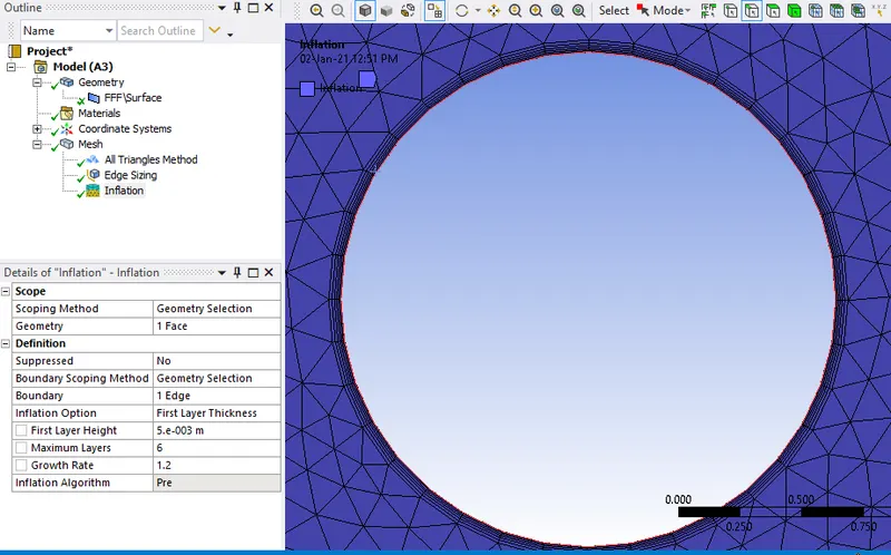
Provide inflation layer at the wall of cylinder to get the smooth flow at the surface of cylinder.
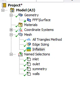
Naming the mesh as inlet, outlet, symmetry and wall (surface of cylinder) which helps in correct implementation of BCs.
Fluent setup:- Select laminar model & create custom material.
Material properties- Density= 1 kg/m^3
Viscosity= 0.02 kg/m.s
Boundary condition- Inlet, velocity= 1 m/s
Outlet, pressure= 0 Pa
Walls= wall, no slip boundary condition
Symmetry=Symmetry
PART-1
Simulate the flow with the steady and unsteady case and calculate the Strouhal Number for Re= 100
Steady Flow Simulation-
Re= 100
Inlet velocity= 1 m/s
Material Density= 1 kg/m^3
Viscosity= 0.02 kg/m.s
Residual Plot-
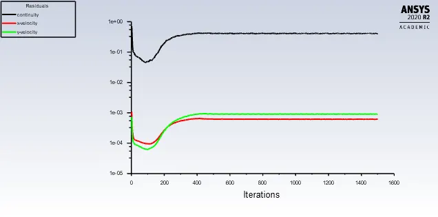
The solution is converged at 300 iterations.
Vertex average velocity-
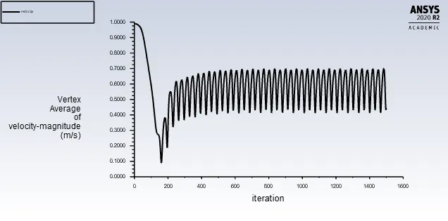
There is vortex shedding/von karman street effect take place because Re number is more than 40.
Drag coefficient (cd)-
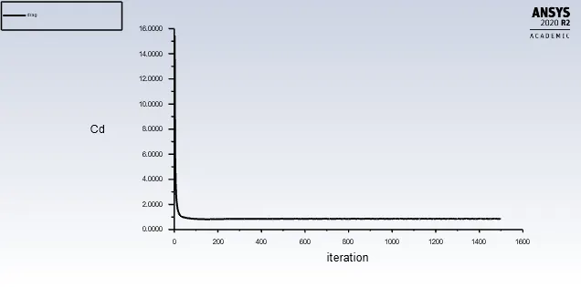
Drag coefficient is 0.862
Lift coefficient-
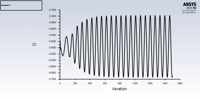
Lift coefficient is 0.086
Velocity contour-
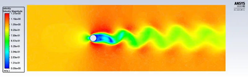
Pressure contour-
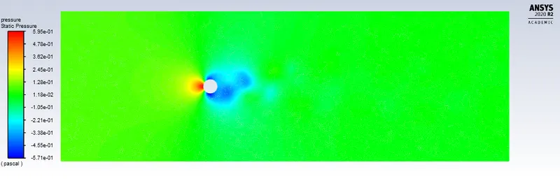
Unsteady state:-
Timestep size= 0.1 second
Timesteps= 2000
Residual plot-
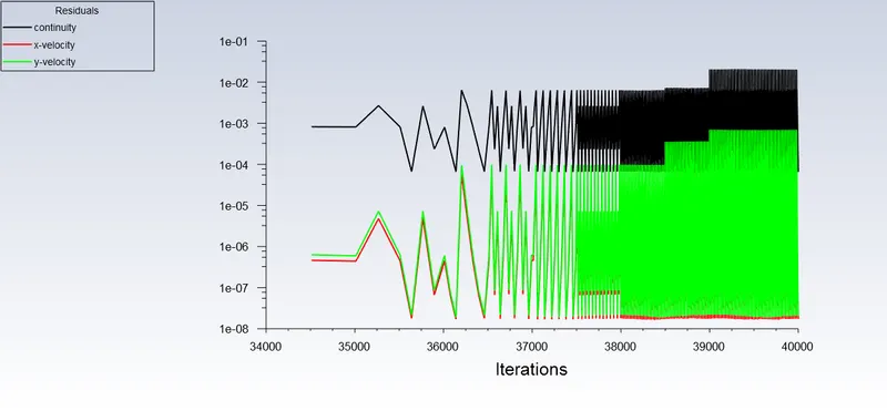
The solution is converged at 38000 iterations.
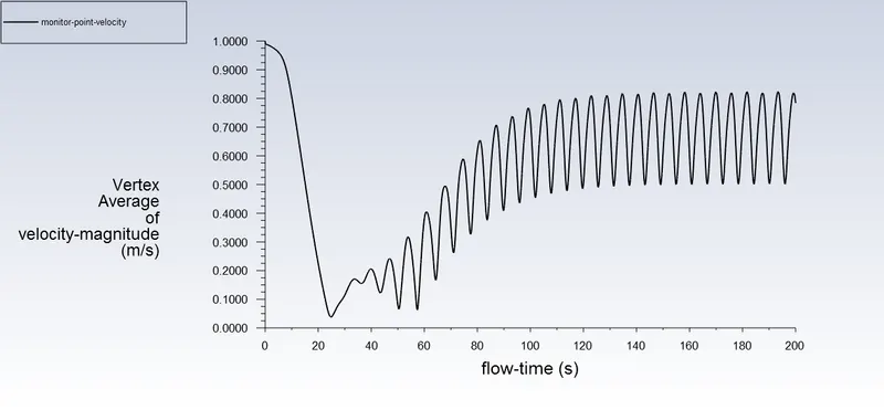
vertex average velocity-
Drag coefficient(cd)-
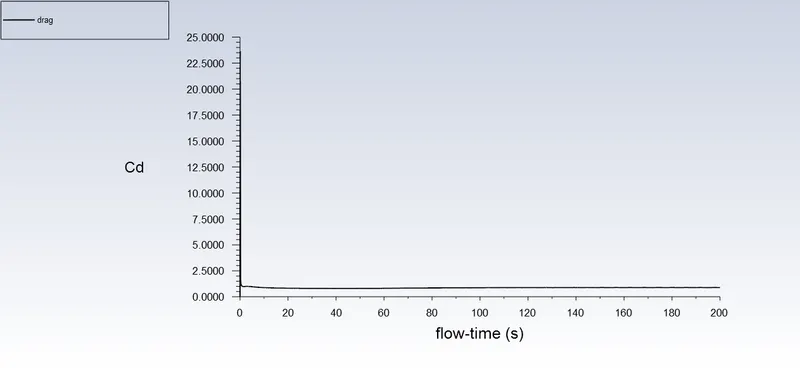
Drag coefficient is 0.888
Lift coefficient(cl)-
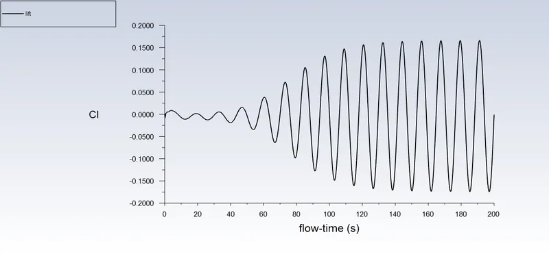
Lift coefficient is 0.000739
Velocity contour-
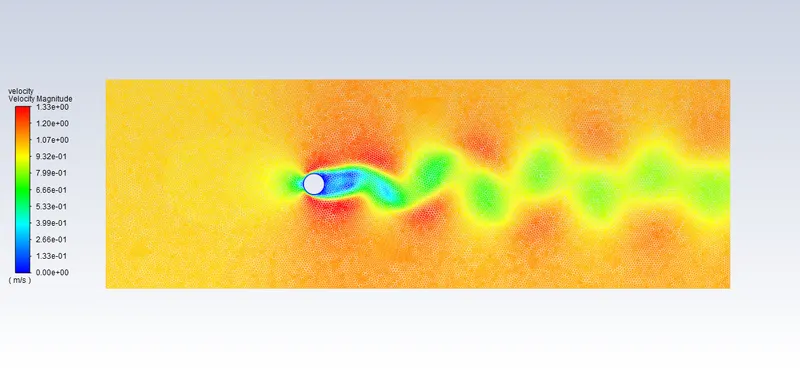
Pressure contour-
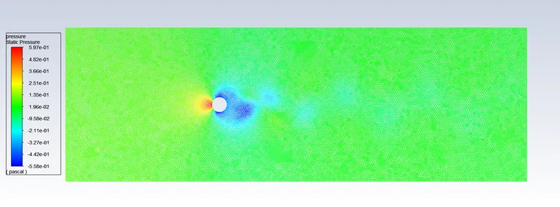
Strouhal Number= Oscillation/mean speed=(f*L)/velocity= (0.75*2)/1 = 0.15
where, f= Number of cycle/Time of cycle= 1.5/20 = 0.75
------------------------------------------------------------------------------------------------------
PART-2
Calculate the coefficient of drag and lift over a cylinder by setting the Reynolds number to 10,100,1000,10000 & 100000. (Run with steady solver)
Steady Flow Simulation-
Material Density= 1 kg/m^3
Viscosity= 0.02 kg/m.s
Case-1: Re=10, inlet velocity= 0.1 m/s
Residual plot-
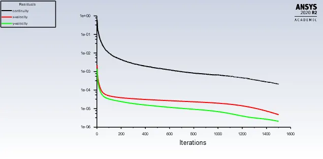
The solution is converged at 300 iterations
Vertex average velocity-
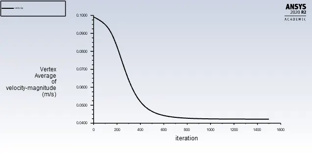
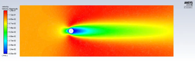
Re number is less than 40, so there is no von karman street effect.
Drag coefficient(cd)-
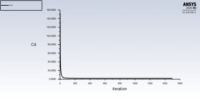
The drag coeff. is 2.120
Lift coefficient(cl)-
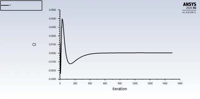
The lift coeff. is 0.00039
Velocity contour-
Pressure contour-
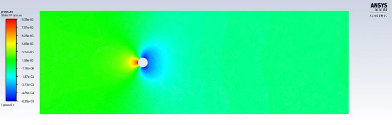
Case-2: Re=100, inlet velocity= 1 m/s
this case is discussed above during Part-1 steady state simulation.
Case-3
Re=1000, inlet velocity= 10 m/s
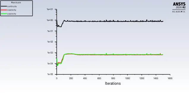
Residual plot-
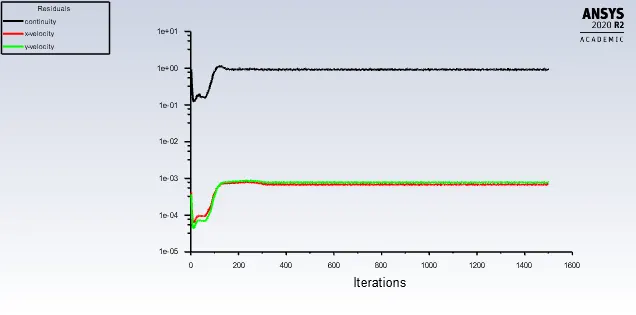
The solution is converged at approx.300 iterations
Vertex average velocity-
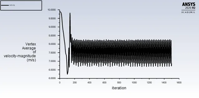
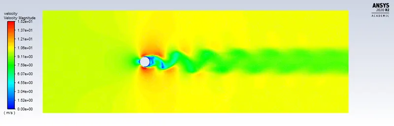
Re number is more than 40, so there is von karman street effect take place.
Drag coefficient(cd)-
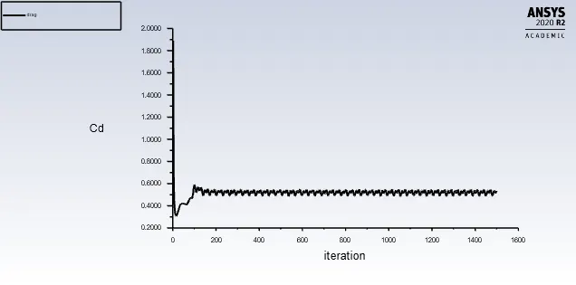
The drag coeff. is 0.544
Lift coefficient(cl)-
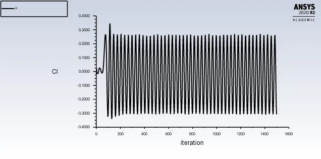
The lift coeff. is 0.293
Velocity contour-
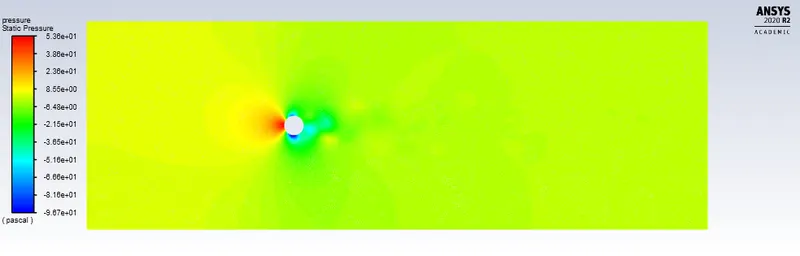
Pressure contour-
Case-4
Re=10000, inlet velocity= 100 m/s
Residual plot-
Vertex average velocity-
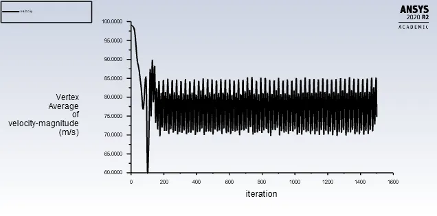
Re number is more than 40, so there is von karman street effect take place.
Drag coefficient(cd)-
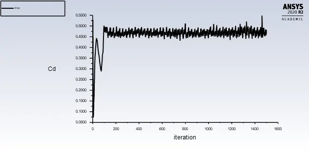
The drag coeff. is 0.487
Lift coefficient(cl)-
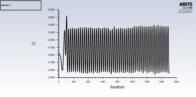
The lift coeff. is 0.229
Velocity contour-
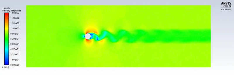
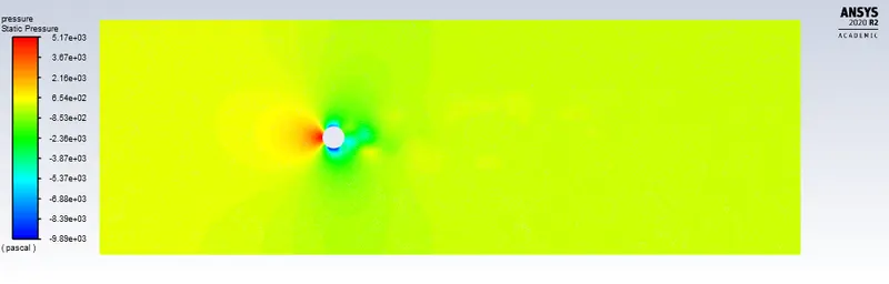
Pressure contour-
Case-5
Re=100000, inlet velocity= 1000 m/s
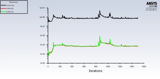
Residual plot-
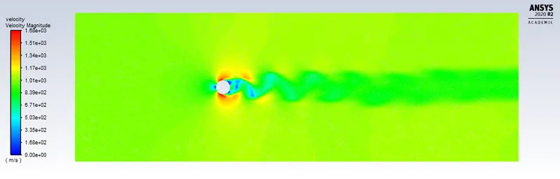
Vertex average velocity-
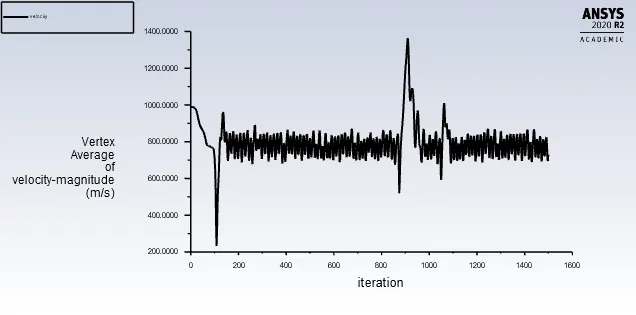
Re number is more than 40, so there is von karman street effect take place.
Drag coefficient(cd)-
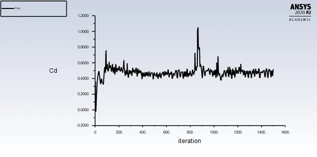
The drag coeff. is 0.496
Lift coefficient(cl)-
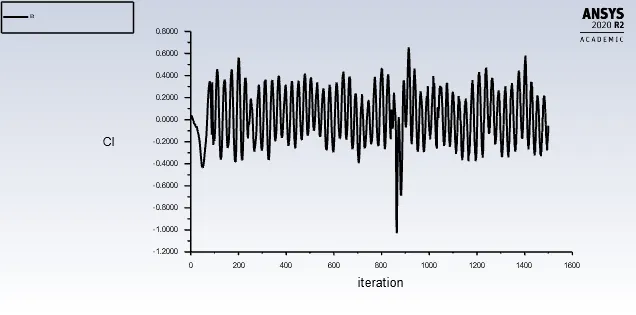
The lift coeff. is 0.055
Velocity contour-
Pressure contour-
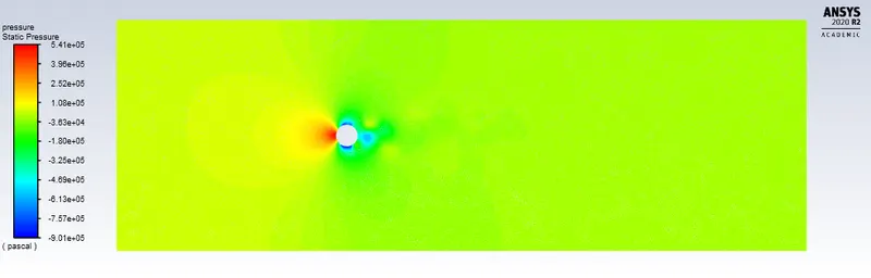
The effect of Reynolds number on the coefficient of drag-
| Simulation | Reynolds Number | Drag Coefficient (cd) | Lift Coefficient (cl) |
| steady state | 10 | 2.12 | 3.90E-04 |
| steady state | 100 | 0.862 | 0.086 |
| transient state | 100 | 0.888 | 0.000739 |
| steady state | 1000 | 0.544 | 0.293 |
| steady state | 10000 | 0.487 | 0.229 |
| steady state | 100000 | 0.496 | 0.055 |
Conclusion:-
As per above simulation results, when Reynold number increases, then drag coefficient is decreases. Because high Reynold number (Re>4000) leads to turbulent flow, hence viscous effect become small. So lower drag take place.
And when Reynold number decreases (Re<2300), then flow is laminar, hence viscous effect is large so that drag coefficient increases.
Animation:-
For steady flow Re number= 100