Roof challenge
AUTOMOTIVE CAR ROOF DESIGN
Aim: To create side flanges and reinforcements (roof rails) for the given car roof skin and also carry out curvature study along with draft analysis.
Introduction:
An automobile roof or car top is the portion of an automobile that sits above the passenger compartment, protecting the vehicle occupants from sun, wind, rain, and other external elements. The roof itself may be constructed of soft or rigid material.
There are various types of roof design were developed over the past years, such as
- Convertible roofs
A convertible or cabriolet is a passenger car that can be driven with or without a roof in place. The methods of retracting and storing the roof vary among eras and manufacturers.
A convertible car's design allows an open-air driving experience, with the ability to provide a roof when required. A potential drawback of convertibles is their reduced structural rigidity (requiring significant engineering and modification to counteract the effects of removing a car's roof)
- Hardtops
A hardtop is a rigid form of automobile roof, which for modern cars is typically constructed from metal. A hardtop roof can be either fixed, detachable for separate storing or retractable within the vehicle itself.
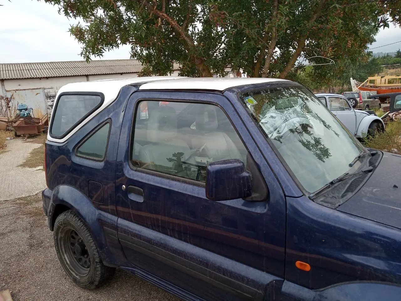
The pillarless hardtop is a body style of cars without a B-pillar, which are often styled to give the appearance of a convertible design.
- Sunroofs
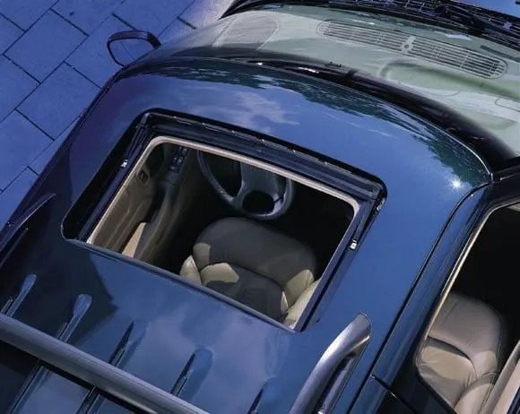
A sunroof is a movable panel that opens to uncover a window in an automobile roof, allowing light and fresh air to enter the passenger compartment. Sunroofs can be manually operated or motor driven, and are available in many shapes, sizes and styles. While the term "sunroof" is now used generically to describe any glass panel in the roof, the term "moonroof" was historically used to describe stationary glass panes rigidly mounted in the roof panel over the passenger compartment.
- T-tops
A T-top is an automobile roof with a removable panel on each side of a rigid bar running from the center of one structural bar between pillars to the center of the next structural bar. The panels of a traditional T-top are usually made of auto grade safety glass.
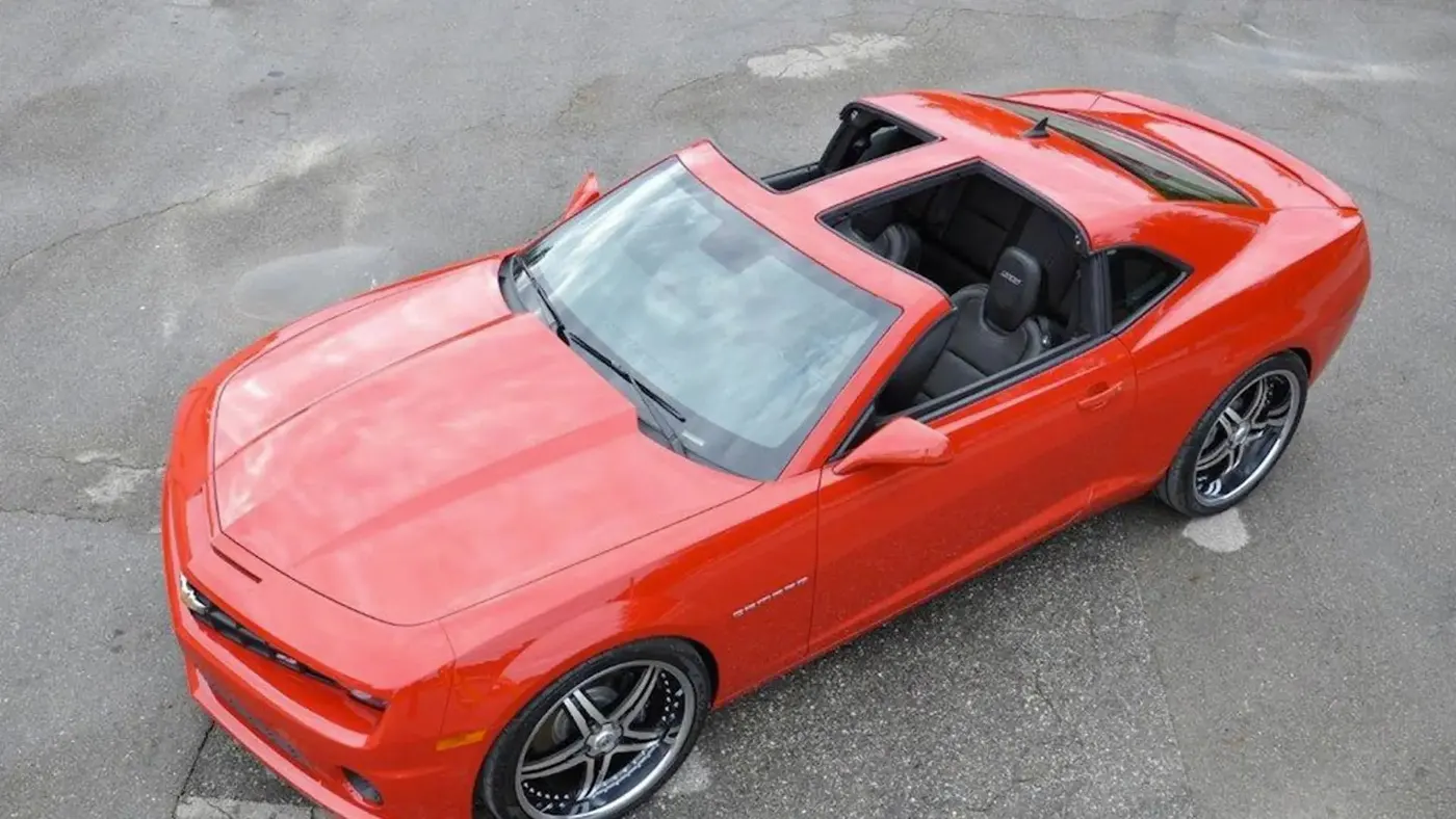
The 1968 Chevrolet Corvette coupe was the first U.S.-built production automobile to feature a T-top roof. This increased the popularity of the coupe, such that it outsold the convertible and later led to the discontinuation of the Corvette convertible after 1975 until it was revived in 1986.
- Targa tops
Targa top, or targa for short, is a semi-convertible car body style with a removable roof section and a full width roll bar behind the seats. The term was first used on the 1966 Porsche 911 Targa.
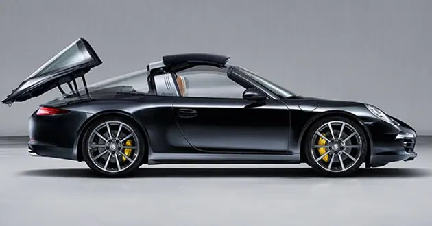
The rear window is normally fixed, but on some targa models, it is a removable plastic foldable window, making it a convertible-type vehicle. Any piece of normally fixed metal or trim which rises up from one side, over the roof and down the other side is sometimes called a targa band, targa bar, or a wrapover band. Targa tops are different from T-tops, which have a solid, non-removable bar running between the top of the windscreen and the rear roll-bar, and generally have two separate roof panels above the seats that fit between the window and central t-bar.
- Vinyl roofs
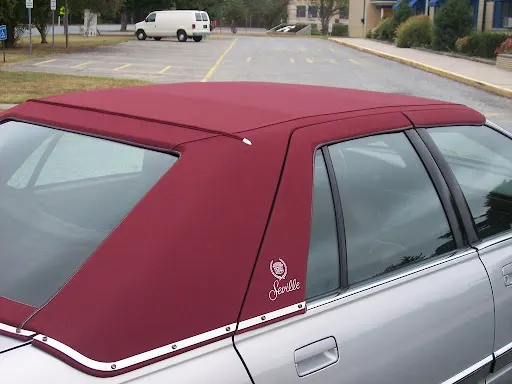
Vinyl roof refers to a vinyl covering for an automobile's top. This covering was originally designed to give the appearance of a convertible to models with a fixed roof and eventually evolved into a styling statement in its own right. Vinyl roofs were most popular in the American market, and they are considered one of the period hallmarks of the 1970s domestic cars.
Automotive Roof Crush Test:
Roof crush is the failure and displacement of an automobile roof into the passenger compartment during a rollover accident.
Apart from the styiling and the strength, Safety is the most important criteria to be taken care while designig the roof panel.
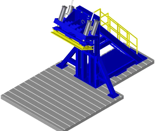
Roof strength evaluations are conducted on a quasi-static test system manufactured by MGA Research Corporation (Figure 3). The system consists of an upright assembly and an attached loading head that can be fixed at varying heights from the ground as well as at pitch angles ranging from −5 to +5 degrees to accommodate testing on the driver or passenger side. The roll angle is permanently fixed at 25 degrees. Four hydraulic actuators control the movement of the platen along two linear guides. The entire system is mounted on a T-slot bed plate anchored to the floor of the test facility.
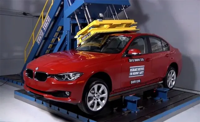
The strength of the roof structure to occupant the protection in real world crashes, requiring the maximum moving distance of the roof structure should be less than 127mm when the induced load is 1.5 times the vehicle weight.
For the test, the passenger car shall be rigidly placed or positioned on horizontal surface with the doors locked and the window closed.
This test can be conducted on either side of the roof structure, the front left or front right side but not on both sides in one single test and still meet the requirements of the test. The rigid plate shall not move faster than 0.5 inches/second and the force applied on the plate shall not exceed the lesser of 1.5 times the unloaded vehicle weight (UVW) expressed in kilograms multiplied by 9.8 or 5000lbs
Also, the direction of the forces shall be downward and perpendicular to the lower surface of the rigid plate and such that moves in a straight line without rotation. The duration of the test shall not exceed 120 seconds. The longitudinal axis of the plate is pitched forward at a 5° angle as viewed from the side of the passenger car.
Manufacturing Process:
In automobile part manufacturing and production process to establish the geometry of a part depending on the shape, the material deformation ability and the process condition without any problem, it is absolutely essential to specify the part material property as well as understanding of the materials parameter. This helps to figure out the limit to which the part material can be formulated without reaching any kind of fracture and deformation.
With the competition of worldwide automobile industry, the forming of auto body panels becomes more important for the increasing requirements of appearance and feasibility. Due to the variety and complexity of auto body shape and its forming process, the traditional methods of qualitative analysis and “trial and error” method are not suitable for the development of modern automotive industry. However, in die making industries the trial and error method cannot vanish. As several scholars reason out that the utilization of traditional method in die making industries is because of the consideration of die deformation [1] . The present leading global automotive manufacturers have been challenged with applying traditional design practices to sheet metal design and assembly. The goal behind this effort is to help achieve high quality auto bodies with minimal lead-time and development costs. Nevertheless, nowadays modeling and simulation are often integrated parts of product and process design in an integrated modernized manufacturing environment.
In sheet metal forming process modeling and simulation can be used for various purposes, such as to predict material flow, to analyses stress, strain and temperature distribution, to determine forming forces, to forecast potential sources of defects and failures, to improve part quality and complexity, to reduce manufacturing costs as well as predicting and eliminating the springback problem.
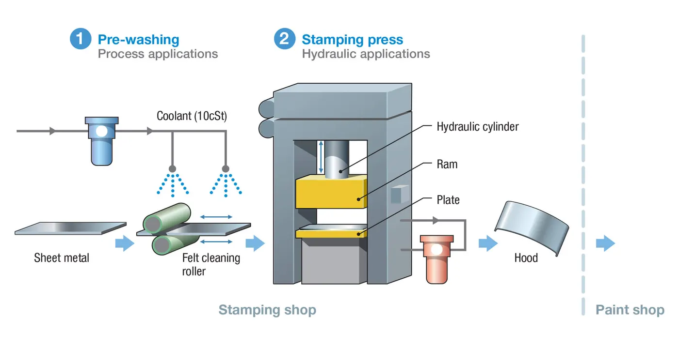
Automotive stamping process:
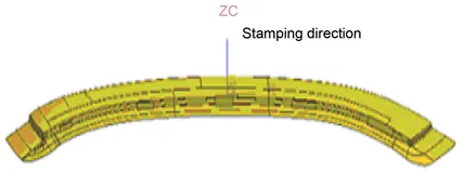
The Automobile roof consists of the following parts:
- The outer panel
- Front roof Rail
- Bow Roof
- Centre Roof Rail
- Rear Roof Rail
Why reinforcements ?
If the roof is flat it is very weak and cannot able to with stand the forces like snow, so in order to increase the strength of the roof these reinforcements like front roof rail, central roof rail, rear roof rail and the bow roofs are introduced and joined to the flat surface of the roof with the different joining process
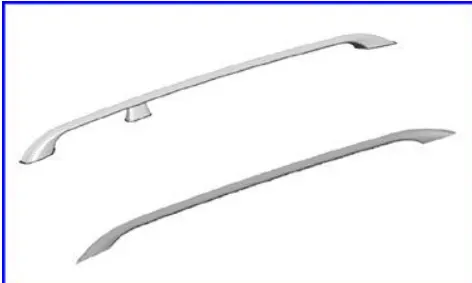
Top Roof Rails:
Roof rails are placed onthe top of the vehicle and are used to carry additional luggage and equipment. Aluminiumextrusions are used for manufacturing roof rails because they enable visually attractive, lowweight and high strength designs.The length of aluminium roof rails can vary significantly, they are found on small cars as wellas on station wagons and MPV's (Multi Purpose Vehicles). Roof rails have two principle functions; to enhance the design features of the vehicle and to carry extra loads placed on theroof, often with the help of another structure, e.g. transverse load bars or a roof box.
Design Criteria:
Roof designed here by following some criteria-
- Draft analysis fro easy manufacturing and tooling
- Heat distortion
- snow load criteria
Data Provided:
Bow–Roof Prediction Formula
W = [1.73 x 10^(-3) x L] + [1.85 x 10^(-8) x (R^2)/t] + [ 1.10x10^(-3) x l] - 2.68
Where,
L = Roof Length in X-Direction[mm](Roof dimension in 0-Y)
R = Roof curvature
R = 2(Rx*Ry)/(Rx+Ry)
Rx = X curvature
Ry = Y curvature
t = Roof plate thickness [mm]
l = Bow Roof Span [mm]
Judgment Condition
OK< 2.7
Snow Load Prediction Formula
Qr = [Iy x t2] / [α x s x [(Rx + Ry)/2]2 x 10-8]
Note: The Qr value given over here is correct. There was a typo error in the formula given in the video.
Where,
α = My x Lx2 x 10-12 , My = Y(Ly-Y)
t = Roof plate thickness [mm]
Ly = Distance between the front and rear roof Rails on the Vehicle along with 0Y[mm]
Length of Roof panel with the center point between Roof rail Front /Rear as the front and rear reference point.
Lx = Distance between the Left and Right end of the roof on the Roof BOW [mm]
The width of the roof panel is exposed on the surface.
Y = Distance front Front Roof Rail to Roof BOW[mm]
s = Distance for which Roof BOW bears divided load [mm]
s = L1/2 + L2/2
Iy = Geometrical moment of inertia of Roof BOW (Y cross-section )[mm4]
Rx = Lateral direction curvature radius of roof panel Y cross-section on Roof BOW [mm]
Roof panel curvature Radius of the Length Lx in Front view
Ry = Longitudinal Direction curvature radius of the Roof panel X cross-section on Roof BOW [mm]
Roof panel X curvature radius of length s in Side view
Judgment condition
Qr ≥ 3.1
250 ≤ s ≤ 380
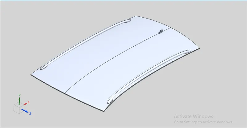
Roof Skin:
Design Procedure:
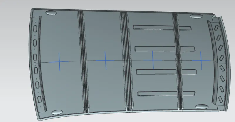
First the surfae from the above styling suraface is extracted as reference,
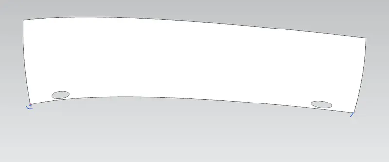
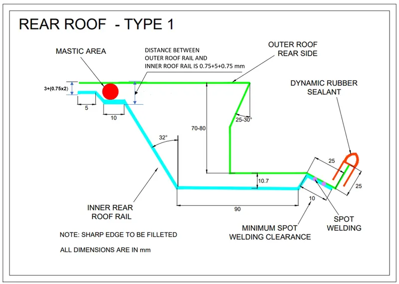
The master section for the roof ditch area, front roof rail, rear roof rail, bow roof rail and center roof rail are proved.
1. Front and Rear Ditch Area:
Flange of around 15mm created with the law extension command, corner relief at rear flanges and positive draft more than 7 degree considering for the drawing operation process. Overall thickness of sheet metal consider 0.75mm throughout.
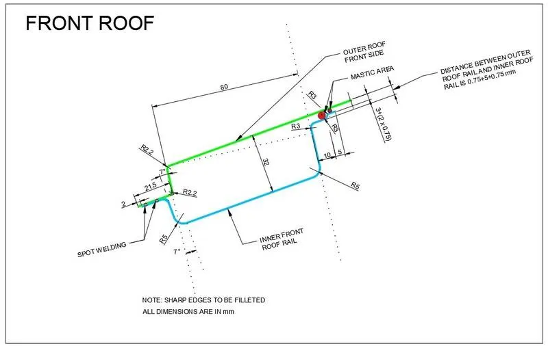
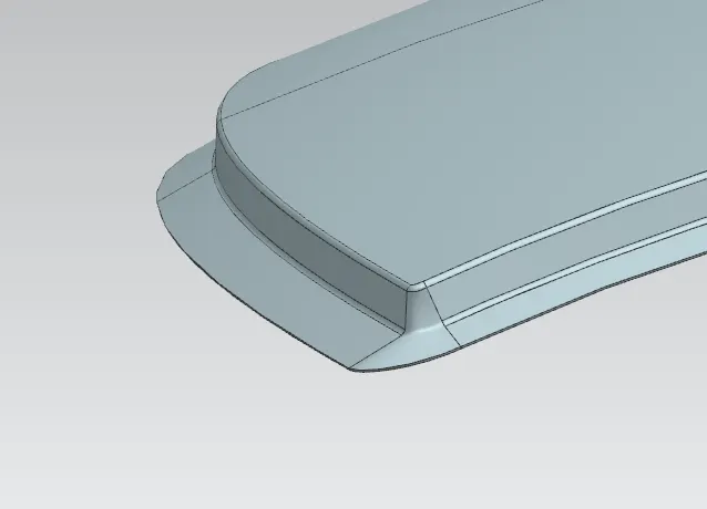
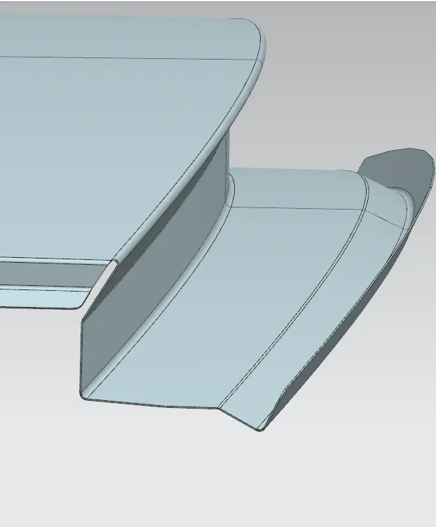
Similarly, the rear ditch area is also created using below master section.
Surface is offset from the outer panel to form the ditch area and with the law extension command, positive draft in required degree considering for the drawing operation process.
2. Front Roof rail:
The front rail underpins the rooftop external shell at the front end. It is mounted with support rooftop rail fortification on the two closures. The rails are furnished with embosses to improve the strength over length and the rail is associated with the external board utilizing mastic sealants on one side and the other joinery is spot welded.

3. Bow Roof Rail 1:
The Bow roofs are given to improve the torsional stiffness and load-bearing capacity of the roof structure. The number of bow roofs provided will depend upon the overall dimensions of the roof. Longer the roof more the bow roofs are integrated to BIW frame They are attached to the outer panel using mastic sealants.
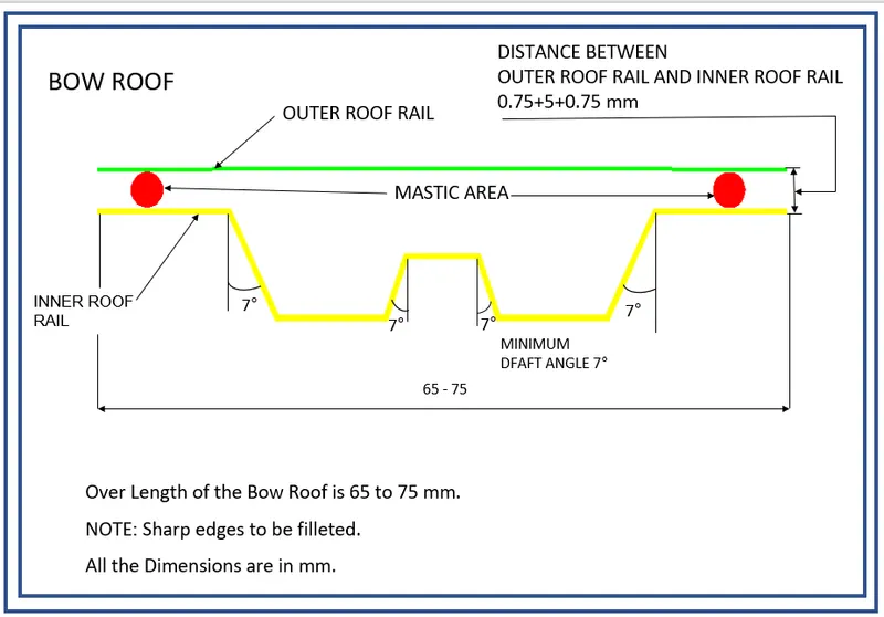
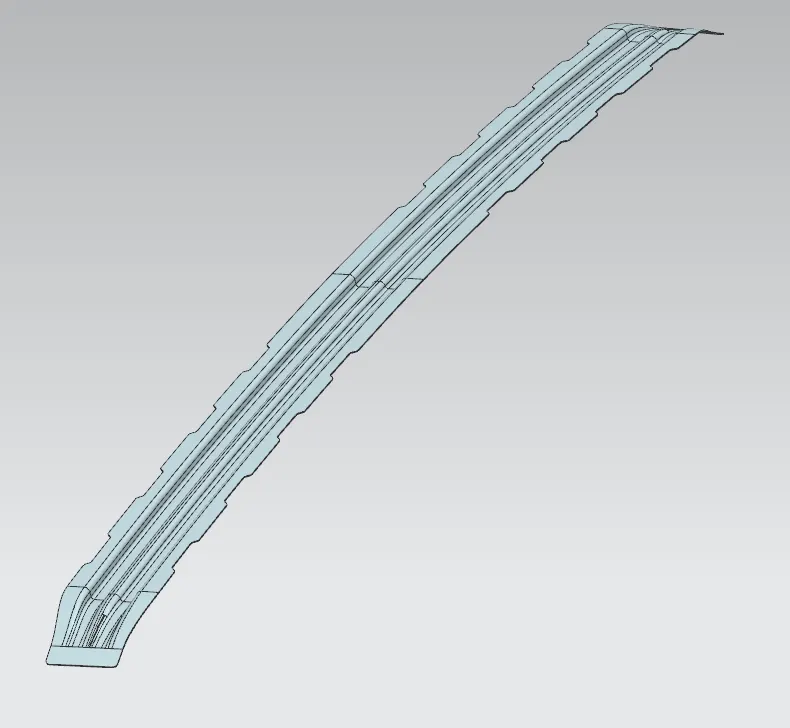
The thickness of the Bow Roof is 0.75 mm
4. Bow Roof Rail 2:
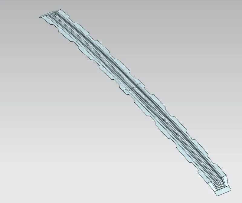
5. Center Roof rail:
Centre roof rail is provided to effectively support the flat area of the roof as it is more susceptible to failure under the action of the load.
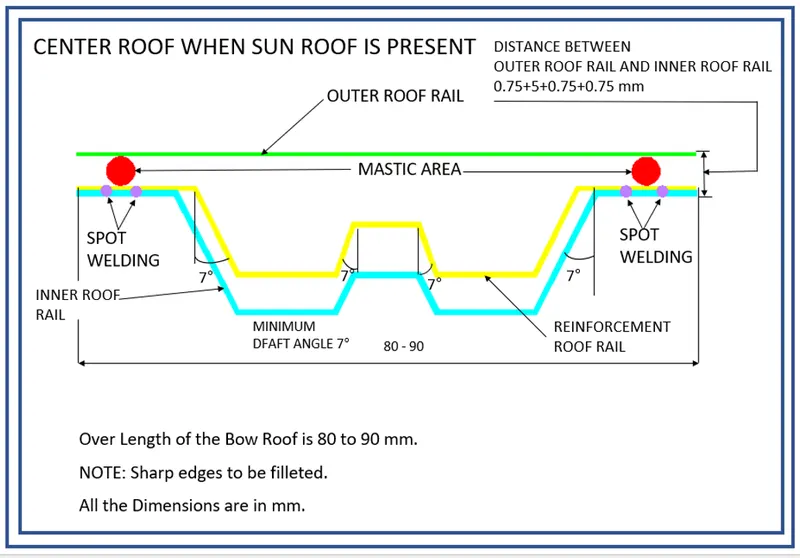
Usually, the centre reinforcement roof rail will be placed at the centre of the roof connecting the B pillar support structure which results in added support in the roll-over test.
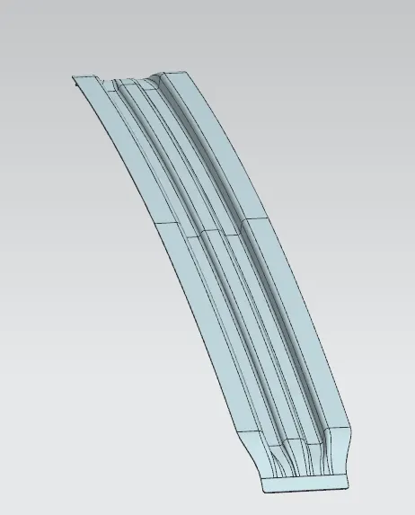
The center roof is spot welded with the reinforcement roof rail and the reinforecement roof rail in attach to the roof panel with the help if mastics.
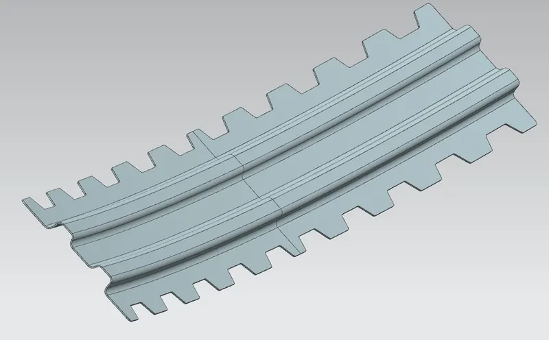
6. Rear roof Rail:
It is the support which is joined to the Back Door and the Body Side Outer and the inner panels.
It is also usually made from Body Side Outer scrap and therefore the thickness of the rail is 0.75 mm.
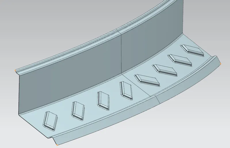
Embosses are created to provide strength to the material.
Mastics are introduced between the roof outer panel and the reinforcements for joining. where ever the mastic are introduced there is remarkable improve of the strength.
Spot welding is also introduced to join the reinforcements and the outer panel.
Assembly:
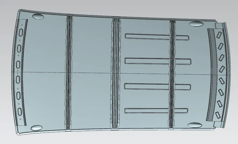
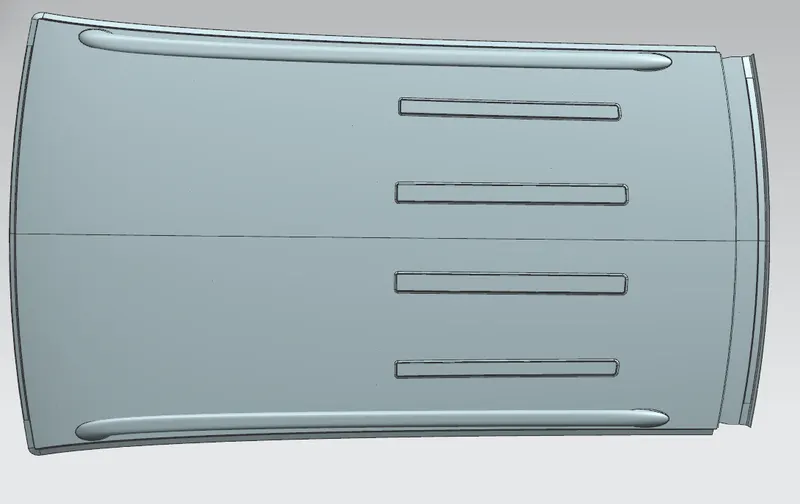
The heat distortion study plays an important role in sheet metal usage. Heat distortion temperature is a temperature limit above which the material cannot be used for structural applications. This study is used to predict the heat distortion temperature at where the material starts to soften when exposed to a fixed load at elevated temperature. In order to avoid bending or damages on roof, based on heat distortion temperature, this study will predict the bow roof position on the roof to strengthen the roof.
Heat Distortion Calculation
W = [1.73 x 10^(-3) x L] + [1.85 x 10^(-8) x (R^2)/t] + [ 1.10x10^(-3) x l] - 2.68
Judgement Condition : OK< 2.7> 3.1
- On plane parallel to the top plane draw sketch in which 0Y line is offset by 300 mm.
- Draw lines perpendicular to 0Y line passing through point exact midpoint of the two adjacent parts (e.g. midpoint between front rail and bow roof 1)
- Offset these reference lines on both sides by 100 mm
- Mark intersection points of reference line and 100 mm offset lines.
- These reference points are then projected on to roof outer panel surface to create curves.
- Take all necessary measurements required to calculate W value as per mentioned formula.
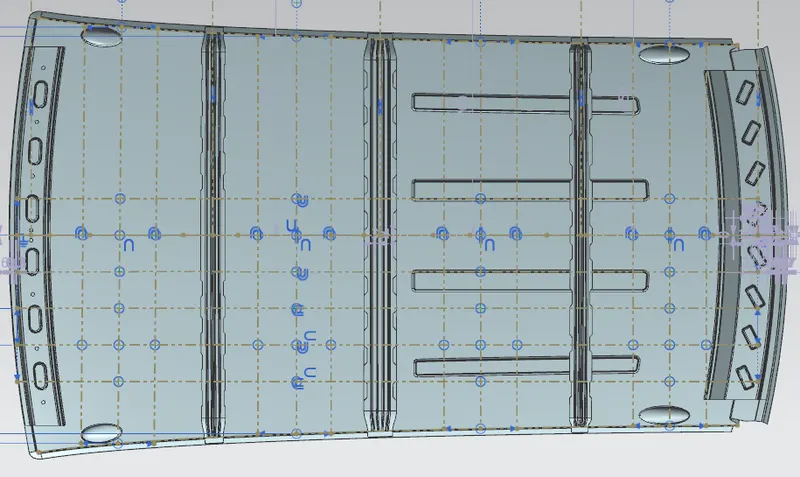
- These points are project on the roof outer panel surface and usinf 3 point arc the points are connected.
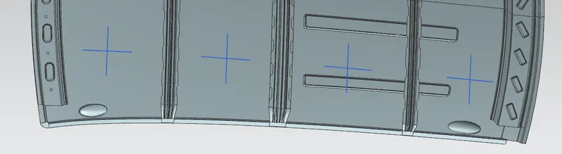
Now the radius of each arc calculated as shown below:
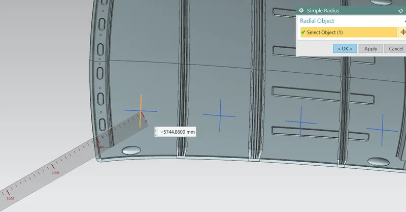
Now the values of Rx and Ry are calculated for all the arcs.

From the above table it can be concluded that all values of W< 2.7 and also not W>3.1 so thus infers that current positioning of Bow roof are good in state as per design and found OK.
Snow Load criteria
Snow load criteria study is done to check the durability of the roof to withstand snowfall and reflex back to its original shape without any permanent deformation once the load is removed.
Qr = [Iy x t2] / [α x s x [(Rx + Ry)/2]2 x 10-8]
Where
α = My x Lx2 x 10-12 , My = Y(Ly-Y)
Procedure:
- At 0-Y axis on perpendicular plane to roof as shown in fig. draw 100 mm lines offset to either side of 0Y axis line. Now centre lines are drawn between each adjacent roof rail edges respectively. Intersection points are marked on the sketch and exit the sketch. Make all geometry in construction lines except the points.
- Project the intersection points in the sketch to roof surface as shown in fig.
- Join the projected curves using arc curve and measure the minimum radius and linear dimension.
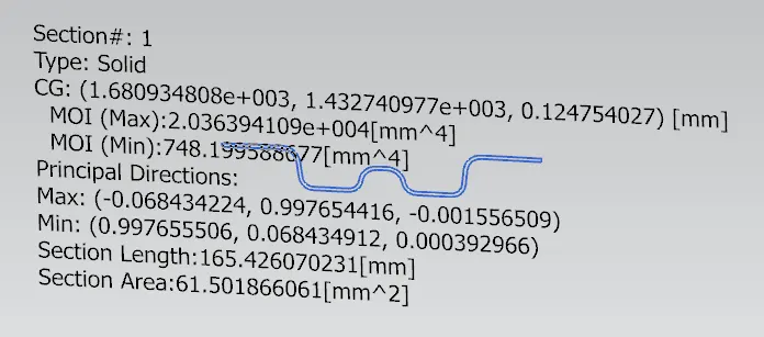
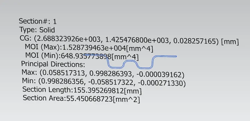
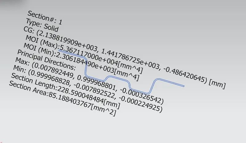
- Project the intersection plane bow roof and centre roof rail on the horizontal plane to find the moment of inertia of the respective section to find Iy values.
- Put all the linear and radial dimension in following formula to calculate Qr Value.
Now we have to calculate the section modulus of the Bow rails and Center rail.
First create an intersection curve of the rail surface with reference to the XY plane.
Then using Section Inertia analysis option the section modulus of the closed loop surface is estimated.
Bow rail 1:
Bow rail 2:
Center rail:
All the calculated values are tabulated and the Qr is calculated accordingly.

Hence the result of snow load criteria shows there is an improvement required for the bow roof rails placement, So we add Emboss to the Outer Panel Roof For better Strength for the Roof.
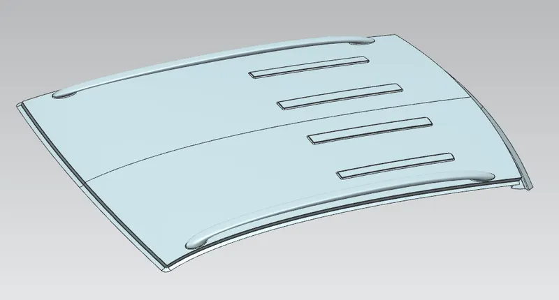
Here since we have used the center roof with a reinforcement rail the strength will be also increased simiultaneously.
The roof emboss are within half of the length of the roof beccause of the addition of sunroof will be provided at the other half.
Draft Analyis
1. Front roof Rail.
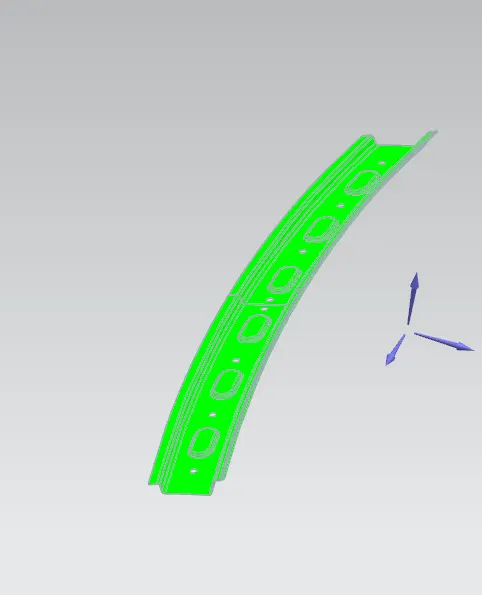
2. Rear roof Rail.
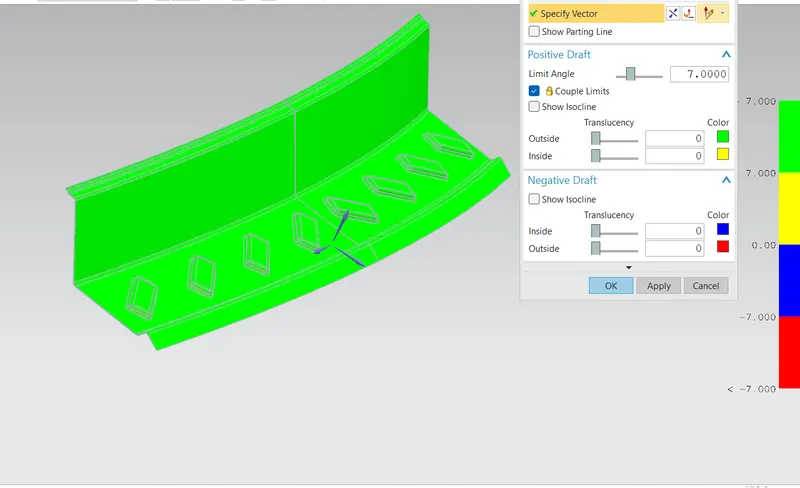
3. Bow roof rail 1 and 2.
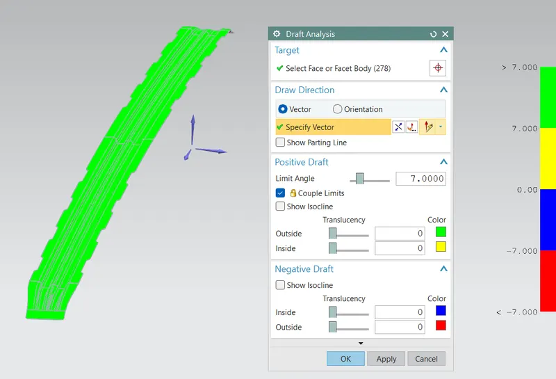
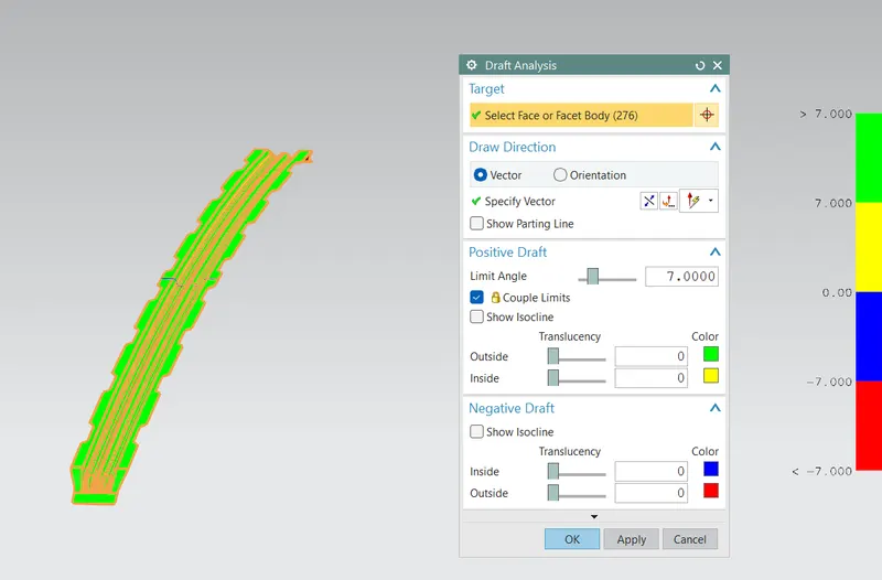
4. Center roof rail and Reinforcement rail.
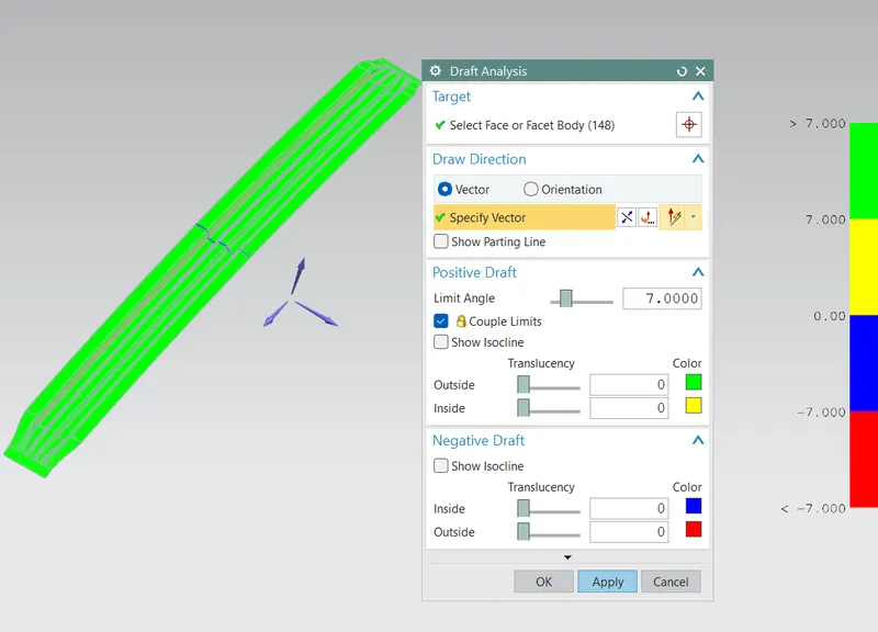
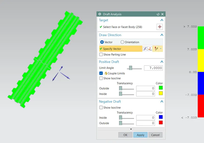
5. Roof outer panel.
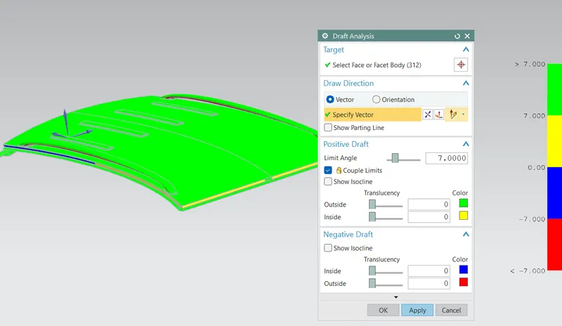
In some of the sections it is seen that there is slight surface error while performing the draft analysis. This report has to be sent to the A team so that they can make proper change in the surface or section.
Conclusion:
- The manufacturing process and the Automotive roof crush test principles are discussed.
- The car roof is designed with the help of the master section provided.
- Curvature study is carried out and neccesary imporvement are suggested like inckusion of embosses in order to increase the strength of the roof.
- Moment of inertia, Section Modulus and Draft analysis are carried out to check the feasibility of manufacturing.