Photo Realistic Rendering
Modelling, Assembly and Photo-realistic Rendering of American Chopper Bike using Solid works.
Objective:
The main purpose / objective of this project is to understand functions of solidworks and solidworks visualize and to model each individual parts of the American chopper bike followed by the assembly.
1. Introduction:
American chopper is a fantasy bike used in American television film series. In this project, the functions of the solidworks 2019 and solidwoks visualise is studied and understood as well as model different parts of the american chopper.
American Chopper conatains of 13 main part components namely,
- Chassis
- Transmission Belt
- Engine
- Front Fork
- front wheel
- Rear wheel
- Chain
- Oil tank
- Gas tank
- Front fender
- Rear fender
- Kick stand
- Pedal
All these part are modelled as per the dimension provided and the complete tools / features are studied before starting the modelling.
2. Medhology / Approach:
In this section, the process flow chart of the step by step procedure carried to comple the project is described as shown below:
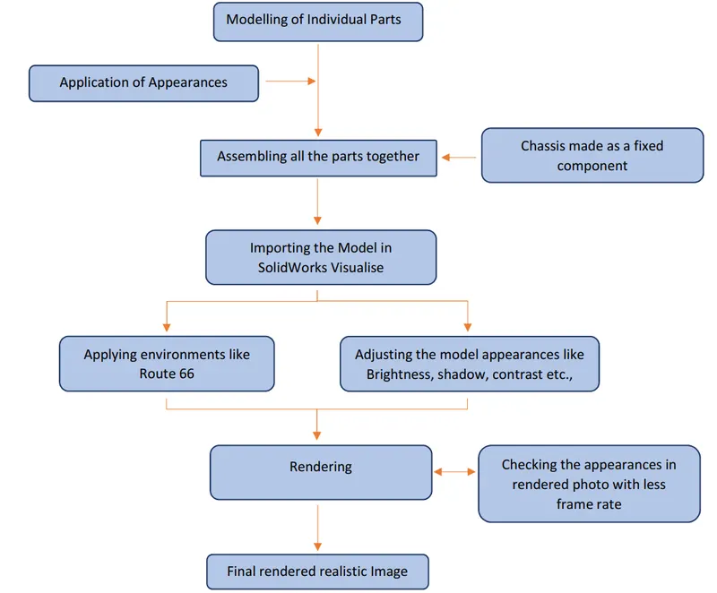
The first step is to understand each feature and tool of the SolidWork software required in model the chopper and the Modelling is proceeded as shown in above flow chart.
According to the application the material appearances are applied to the model. The parts are then assembled taking chassis as the fixed element and all the parts are given relation to it. After the completion of the assembly, the camera angle are applied and the complete model is then imported to SolidWorks Visualise tool for rendering. The model appearance is adjusted and customised according to the respective environment and the final photo realistic rendered image is obtained.
3. Description:
Part Modelling of American Chopped parts:
3.1 Transmission Belt
It is used to tansmit the rotary motion / power from engine to the gearbox and made of flexible material like rubber.
Feature and Commands Used:
- Line
- Circle
- Exrtude Boss
- Fillet
- Appearence
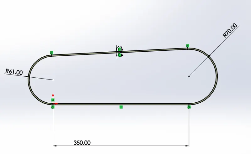
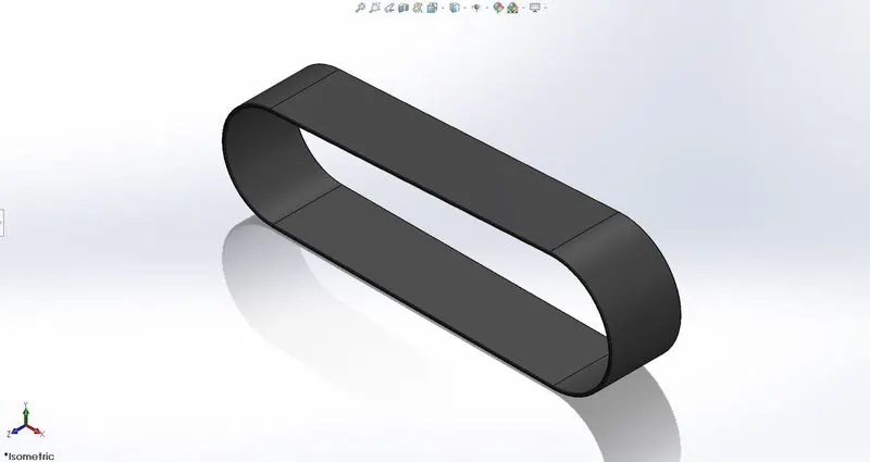
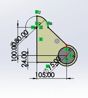
To start with sketching, the fornt plane is selected and the below shown profile is created and the dimension are added accordingly. Make sure the sketch is fully defined. Once the sketch is complete, the Extrude boss function is used to create the 2d sketch to a 3d model with relevant lenght and also the fillet of 1mm is applied to the sharp edges to smoothen it. Apperance is used to specify / add a material or colour to the model according to the application. For transmission belt Matte Rubber is assigned and hence, the model is completed.
3.2 Kick Stand
It is a support to the bike to stand on one side.
Feature and Commands Used:
- Line
- Arc
- Circle
- Dome
- Plane along curve
- Lofted Boss / Base
- Extrude Cut
- Fillet
- Appearence
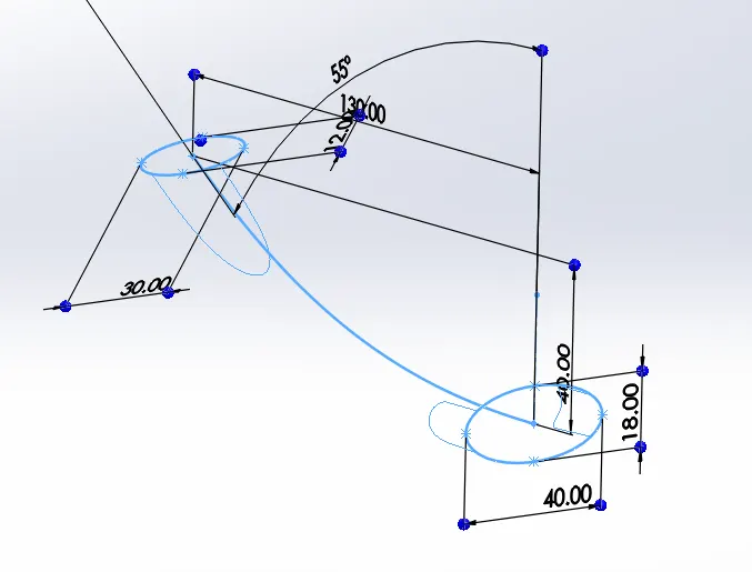
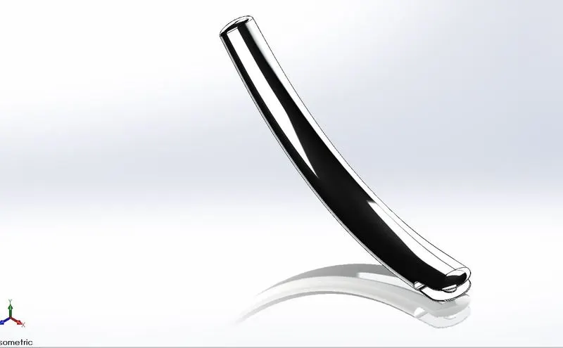
First the arc is sketched on the front plane as shown below. The Plane on curve is selected on the either points of the arc to create a reference plane. Circles are created at the both the planes one by one. Now the sketching isi done. Using Lofted boss the solid model is created. For lofted boss option, both the cirlces drawn are selected as the sketch entities and the arc drawn is selected as the direction curve. Dome feature is applied to the either flat sides of the model with helps to add a elliptical or circular structure on the faces with relevent thickness. Usung Extrude cut the section of the part is removed as shown. In this case Chromiun plate is selected as the appearance.
3.3 Front Fender
It is a protective component placed over the front tyre to prevent the tyre from sand, mud, waste, stone etc.,
Feature and Commands Used:
- Line
- Arc
- Revolve Boss
- Exrtude Cut
- Fillet
- Appearence
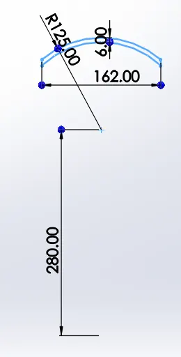
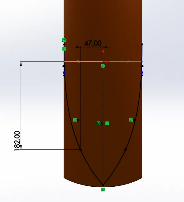
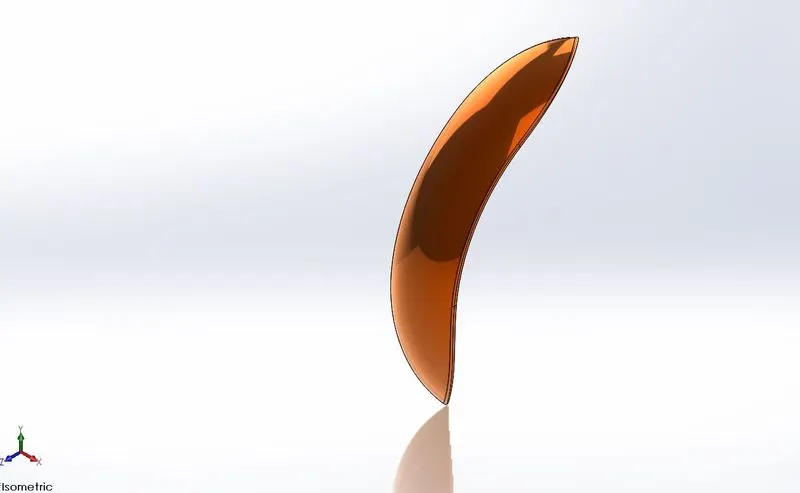
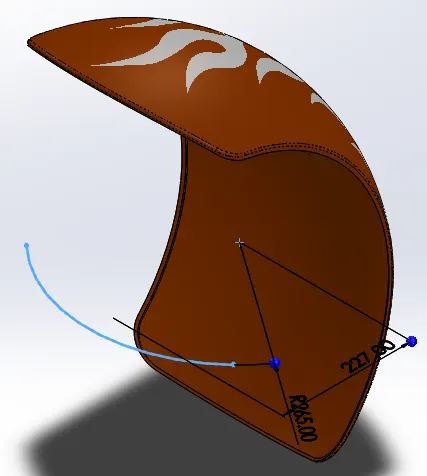
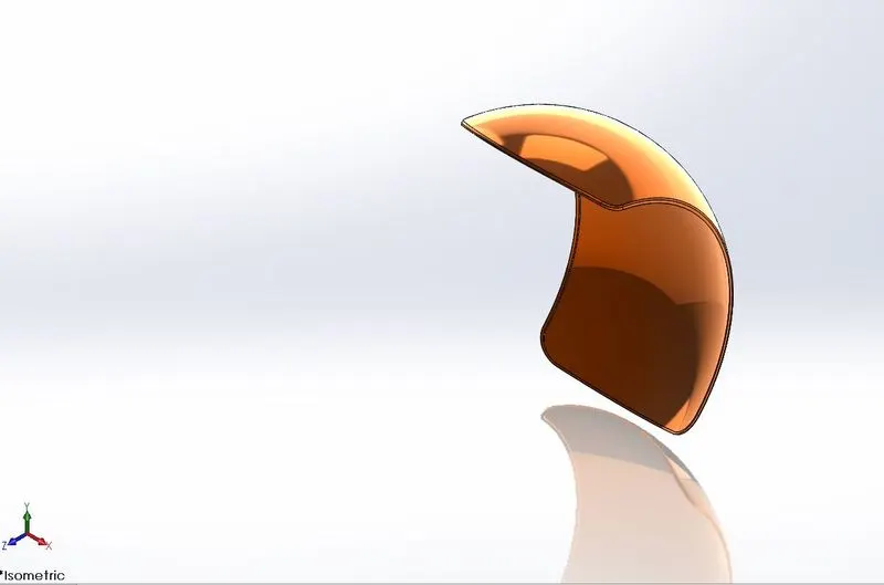
On the front plane, an arc is created (selecting both the ends as horizontal) at appropriate center distance from the origin. An offset of 6mm inwards is applied and both the arcs are connnected with a verticle lines. Using revolve boss option a sketch is selected to be revolved along a appropriate reference axis at the origin to some angle. Then using spline a below shown sketch is drawn and using that sketch with the help of extrude cut option thr required material is removed. Finally, the edges are made using fillet and appearance is assigned.
3.4 Rear Fender
Rear fender is placed over the rear fender and is wide and thicker compared to front fender. The use is same as the front fender.
Feature and Commands Used:
- Line
- Arc
- Exrtude Boss and Cut
- Fillet
- Appearence
On the front plane, an arc is created (selecting both the ends as horizontal) at appropriate center distance from the origin. An offset of 6mm inwards is applied and both the arcs are connnected with a verticle lines. Using revolve boss option a sketch is selected to be revolved along a appropriate reference axis giving an approppraite offset angle to start the revolve. Finally, the edges are made using fillet and appearance is assigned.
3.5 Oil Tank
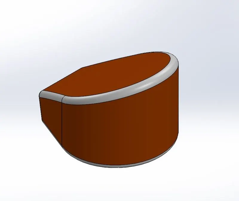
Oil tank mainly contains the lubricant oil for puropofe maintainin the smooth operation of the engine part snad also the cooling it upto some extent to prevent the engine from damage due to high temperature.
Feature and Commands Used:
- Line
- Circle
- Exrtude Boss
- Fillet
- Shell Feature
- Combine Body
- Appearance
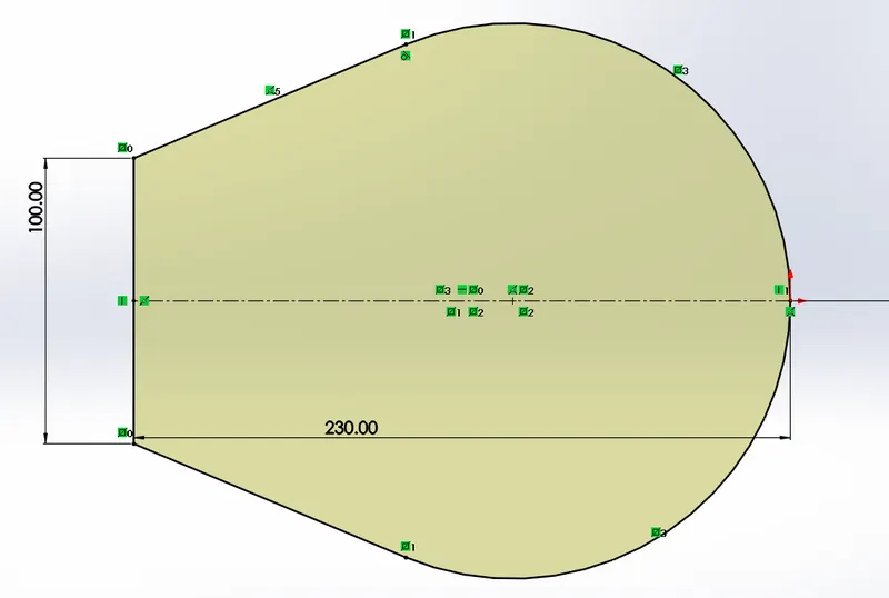
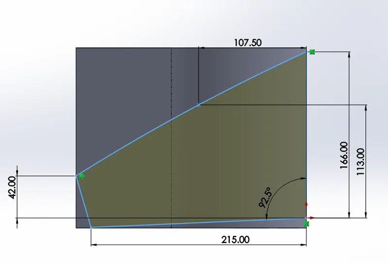
On the Bottom plane, using line and cirlce option the required sketch id drawn and Extruded to appropriate length. Secondly, on the front plane using line command, one more sketch is createdand extruded.
Now using combine option (insert > feature > combine), both the extruded bodies is selected and the required combination is selected from the list of possibilities. Using the shell feature the geometry is made hollow inside. Fillet on the sharp edges and Appearance are assigned accordingly.
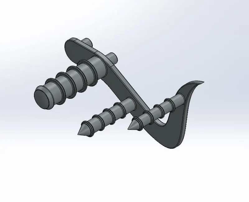
3.6 Pedal
Pedal is a foot-operated lever used to control mechanism like brakes, gear transmission of the vehicle. There are totall two pedal situated on left and right side of the bike.
Feature and Commands Used:
- Line
- Arc
- Spline
- Circle
- Dome
- Exrtude Boss
- Fillet
- Appearence
- Offset
- Linear Pattern
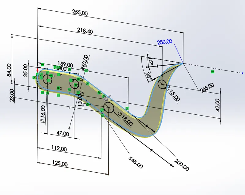
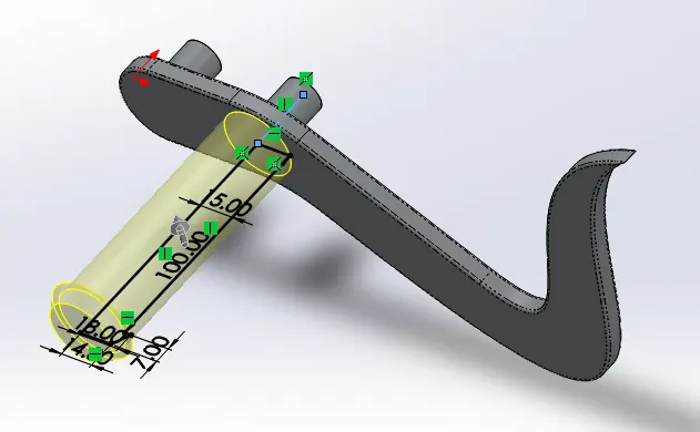
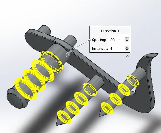
On the front plane using line, circle adn spline function using appropriate dimension the sketch is drawn and extruded. Now on the front of the extruded surface another few sketch are drawn and revolved boss function is performed. Linear pattern is used to make multiple rings on the revolved surfaces at specific equal distances. Chamfer is applied on th two front pedal rods and rest fillet of appropriate value is applied on the sharp edges. Finally appearances are added.
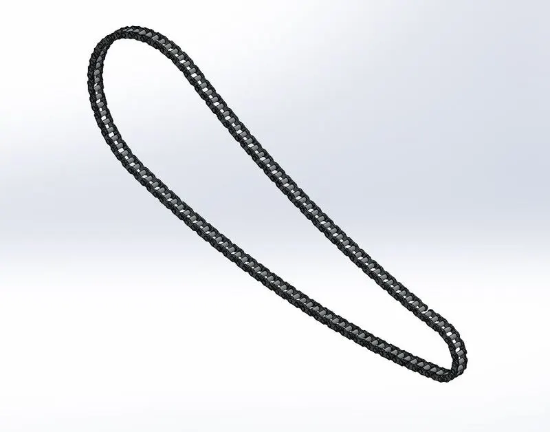
3.7 Chain
The chain acts as a link between the gearbox and rear wheel to transmit the rotary motion / power for the vehicle to move.
Feature and Commands Used:
- Line
- Arc
- Spline
- Circle
- Exrtude Boss
- Dynamic mirror entities.
- Fillet
- Appearence
- Offset
- Pattern along curve
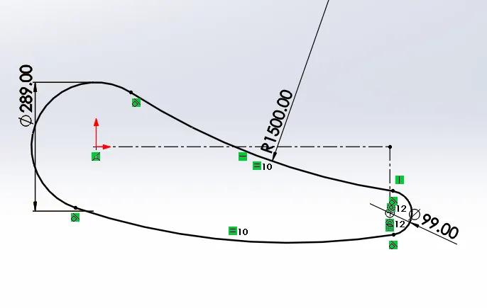
On the front plane the below sketch is drawn which acts as a guide. Two chain plains are drawn and saved as a blocks using block command. Noe based of the guide curve the block sketch is inserted on the starting point of the curve and adjusted. The chain plate is then extruded to appropriate thickness and also offest entity is are used to carate the plate on th eeither side as required. Further, pattern along curve option is selected and the first sketch acts as a guide / reference curve. After completion of the pattern and the solid model, the appearance is added.
3.8 Front Wheel
Front wheel is a component attacted at the front of the vehicle for the purpose of its movement. Also, the main purpose of the front wheel guide / change the direction of the velicle when required.
Features Used:
- Line
- Arc
- Spline
- Circle
- Dome
- Exrtude Boss and Revolve
- Extrude Cut
- Spit
- Dynamic mirror entities.
- Fillet
- Chamfer
- Appearence
- Offset
- Circular pattern
- Combine
- Intersection Curve
- Convert Entity
- Reference Curve etc
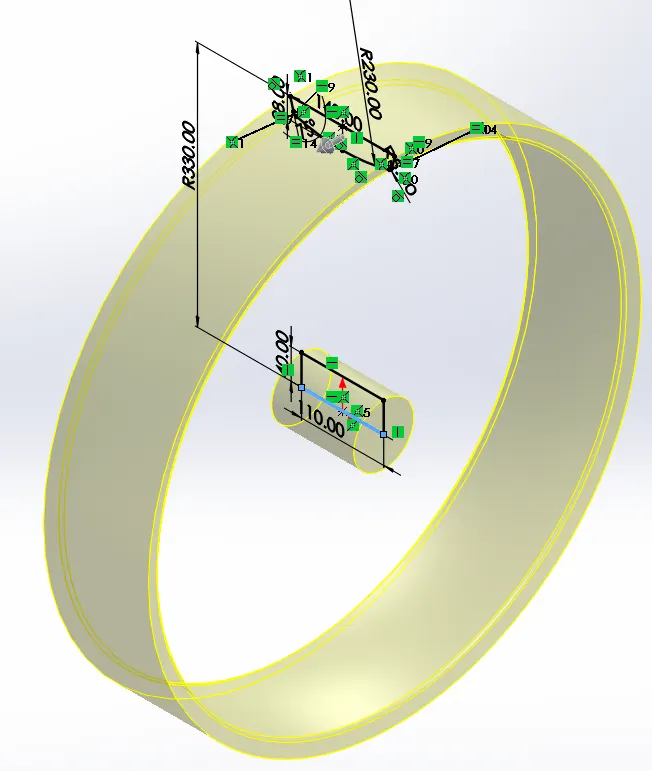
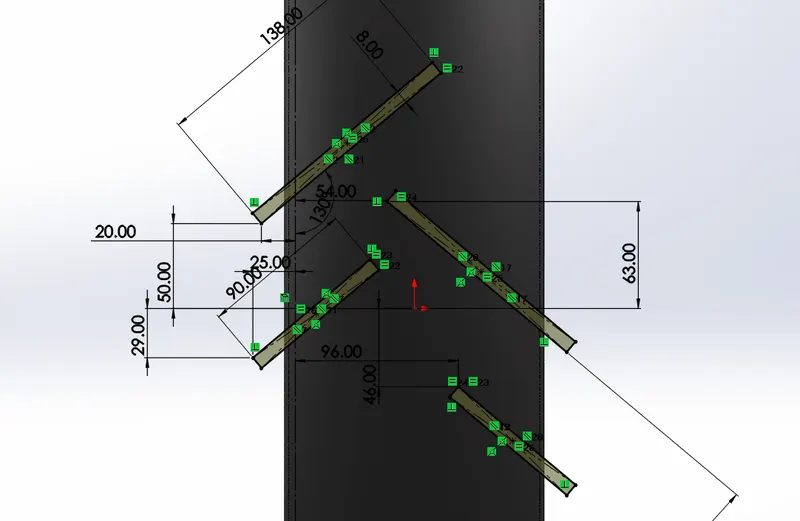
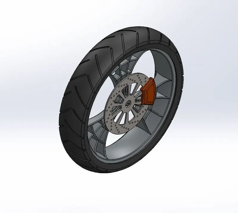
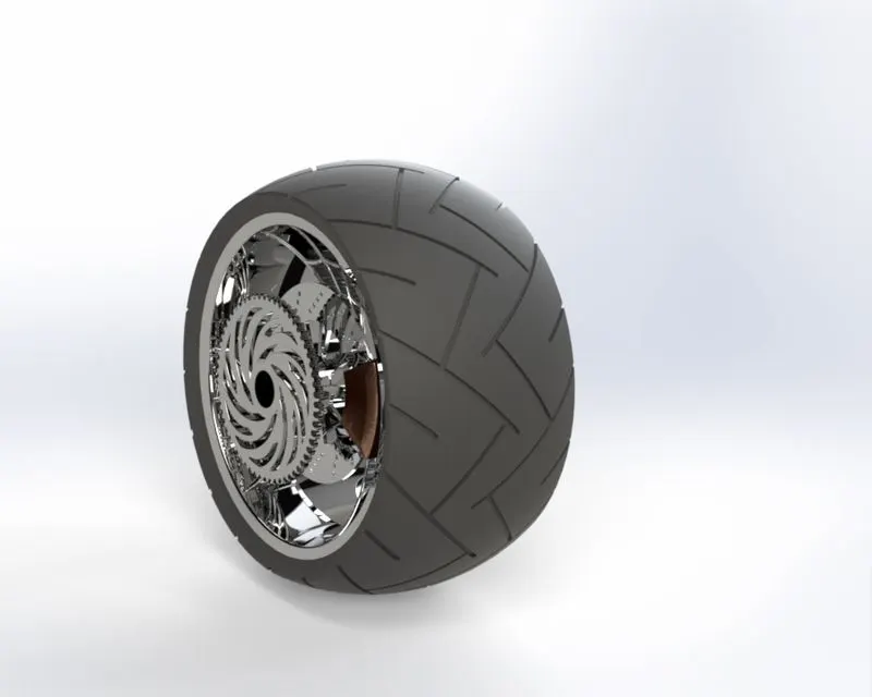
The front wheel mianly consists of tyre, rim, rotor and caliper. To start with first, using revolve extrude function the outer part o the rim is made using appropriate dimension. Now the mian challenge is to design the spider web part inside of the rim. This is made using the tools such as spline and arc and using the extrude boss it is given a thickness. The unwanted material of the part is then removed. Now circular pattern funtion is used to make the multiple web part of the rim. For this the path selected is any one circular geometry whose center is situated at origin. Then by using combine feature the complete rim is combined together and unwanted areas removed.
The rotor is now created at an appropriate distance from the midplane of the rim. Selecting the outer face of the rotor, the geometry of the caliper is drawn and extruded woth reference to midpoint symmetry. Chamfer and fillet is applied at the edges and the corner of the caliper.
Now on the front plane, using arc and line tool the profile of the tyre is drawn and revolved 306 degrees aroung thr axis on the top of the rim. Now the cuts on the surface of the tyre as shown in the following figure. Once all the sketching and modelling is done, corresponding appearance is assinged to each component.
3.9 Rear Wheel
Rear wheel is an object connected to the gearbox through the chain and used to provide circular motion for the movement of the vehivle. It consists of sprocket, caliper, rotor rim and tyre.
Feature and Commands Used:
- Line
- Arc
- Spline
- Circle
- Dome
- Exrtude Boss and Revolve
- Combine
- Fillet
- Appearence
- Revolve Cut
- Circular Pattern
- Dome
- Convert Entity
- Intersection Curve
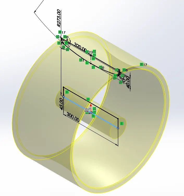
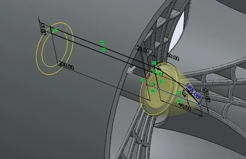
The Rear wheel mianly consists of tyre, rim, rotor, caliper and sprocket. To start with first, using revolve extrude function the outer part o the rim is made using appropriate dimension. Now the mian challenge is to design the spider web part inside of the rim. This is made using the tools such as spline and arc and using the extrude boss it is given a thickness. The unwanted material of the part is then removed. Now circular pattern funtion is used to make the multiple web part of the rim. For this the path selected is any one circular geometry whose center is situated at origin.
The rotor is now created at an appropriate distance from the midplane of the rim. Selecting the outer face of the rotor, the geometry of the caliper is drawn and extruded woth reference to midpoint symmetry. Chamfer and fillet is applied at the edges and the corner of the caliper. Similary, the sprocket is made at an offset from the mide plane and using appropriate dimensions and relations.
Now on the front plane, using arc and line tool the profile of the tyre is drawn and revolved 306 degrees aroung thr axis on the top of the rim. Now the cuts on the surface of the tyre as shown in the following figure. Once all the sketching and modelling is done, corresponding appearance is assinged to each component.
3.10 Front Fork
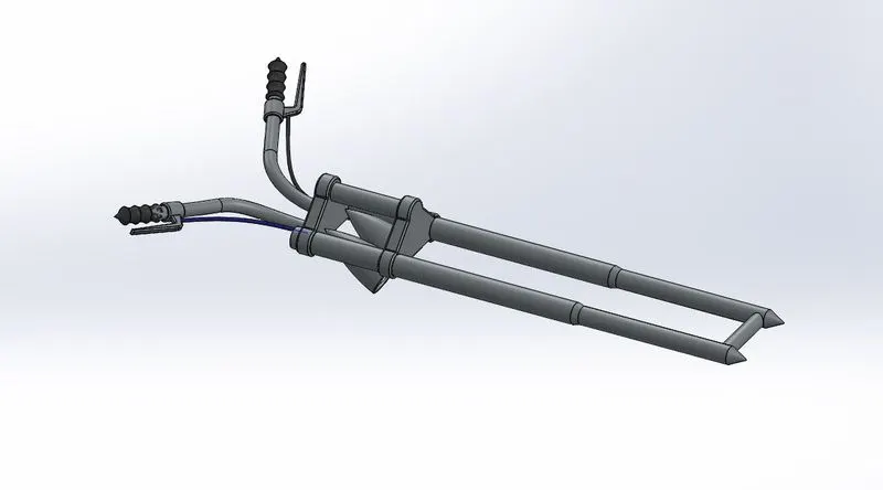
The front fork is the part which holds the front wheel and also the lights, handle and clamp are attached to it. Its as a suspension to the front wheel to absorb shocks and vibrations from the road surface.
Feature and Commands Used:
- Line
- Arc
- Spline
- Circle
- Dome
- Exrtude Boss and Revolve
- Dynamic mirror entities.
- Fillet
- Appearence
- Offset
- Reference Curve
- Projection Curve
- Dome
- Convert Entity
- Intersection Curve
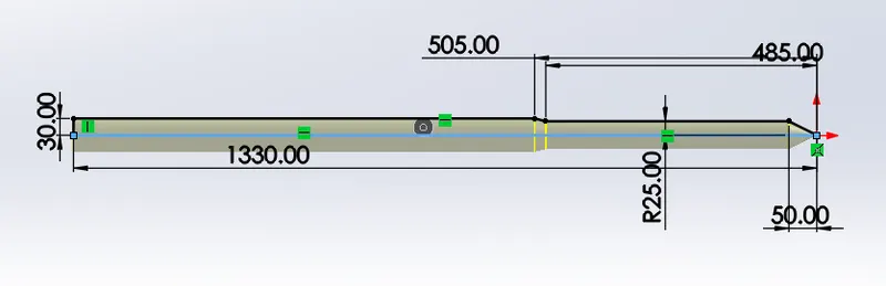
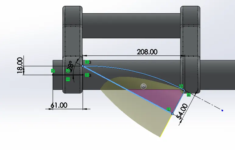
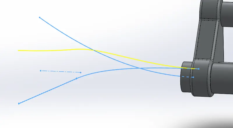
First the fork geometry is drawn on the front plane and using revolve funtion it is made a cirular solid. At one end of it a required geometry is drawn and extruded as show below. It is then patterns at a desired distance. At one end a sketch is drawn at an appropriate angle from the midplane and revolved alon axis to create the headlights. The flat face of the headlight is given a dome section making sure elliptical function is deselected. To create the handle part, various splines are drawn at different plane and the composite curve function is used to get the required curve line. Using sweep funtion the circular section is extruded along the composite cure. Similar procedure is follwed for the brake wire also. Once the half part of the fork is designed. the whole component is mirrored using dynamic mirror entity at the midplane. Atlast the apperances is assigned.
3.11 Chassis
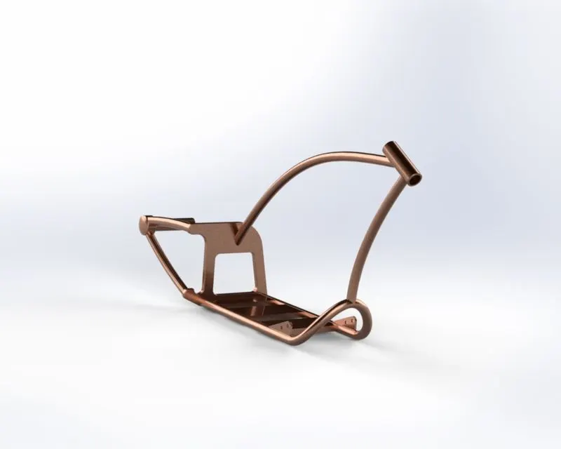
Chassis the most important part of the vehicle. Similar to the human skeleton, it is a skeleton structure of the vehicle body on / to whicl all the part of the vehicle are attached or in simple words it holds all the components of the bike like gas tank, front fork, rear wheel, engine, kick stand, suspension, oil tank, pedal etc.,
Feature and Commands Used:
- Line
- Arc
- Spline
- Circle
- Dome
- Exrtude Boss
- Combine
- Dynamic mirror entities.
- Fillet
- Appearence
- Offset
- Reference Curve etc.
- Projection Curve
- Composirte Curve
- Make Pierce
- Insert Sketch picture
- Revolve Cut
- Circular Pattern
- Dome
- Convert Entity
- Intersection Curve
The front plane is selected and made normal to, then the picture of thre chopper bike is inserted in environment and aligned / adjust along the plane and origin.
First, the lower circular part of the chassis is created on the front plane using spline and line commands. These Lines are projected by using Project curves and composite curves. These Lines are projected by using Project curves. Now using Swept boss is used to create a solid along the projected Curve.
The top angle part is then model by creating a line on front plane and assigning reference plane normal to the end of the line. Two concentric circles are then drawn and extrude along the line.
Now the curved circular rods are then mirrored along the front plane and the bas structures are created between them. At end of the chassis the axle is made which hols the rear wheel. Similarly all other parts of the chassis are made with the healp of the photo and appropriate image.
Fillets are applied at required points to reduce sharpness and make the edges smooth curve.
3.12 Engine
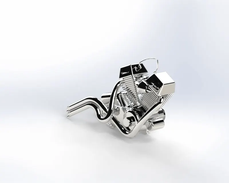
It is the heart of the Vehicle. It is used to convert the chemical energy to mechanical energy due to which the vehical / bike operates or moves.
Feature and Commands Used:
- Line
- Arc
- Spline
- Circle
- Dome
- Exrtude Boss and Revolve
- Combine
- Dynamic mirror entities.
- Fillet
- Appearence
- Offset
- Reference Curve etc.
- Projection Curve
- Composirte Curve
- Make Pierce
- Insert Sketch picture
- Revolve Cut
- Circular Pattern
- Dome
- Convert Entity
- Intersection Curve
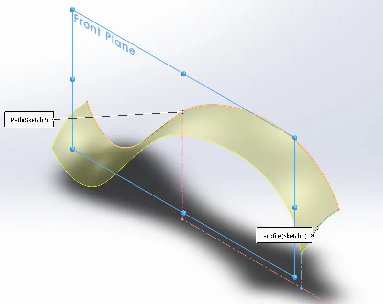
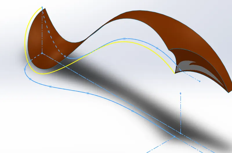
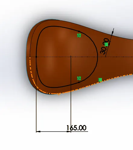
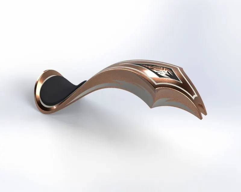
3.13 Gas Tank
Gas is similar to / also called petrol tank or reservoir which contains the flammable fuels. The fuel may be liquid or gas based on application and requirment. It also maintains the temperature low to prevent the fuel from flame / fire.
4. Assembly of American Chopper
The first component selected for assembly is Chassis and this is made a fixed compent. Then all the parts are inserted in a order shown below:
- Chassis
- Engine
- Transmission Belt
- Pedal
- Rear wheel
- Chain
- Oil tank
- Kick stand
- Front Fork
- Front Wheel
- Rear fender
- Front Fender
- Gas Tank
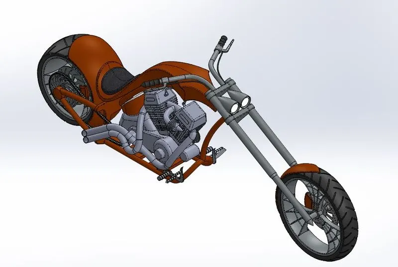
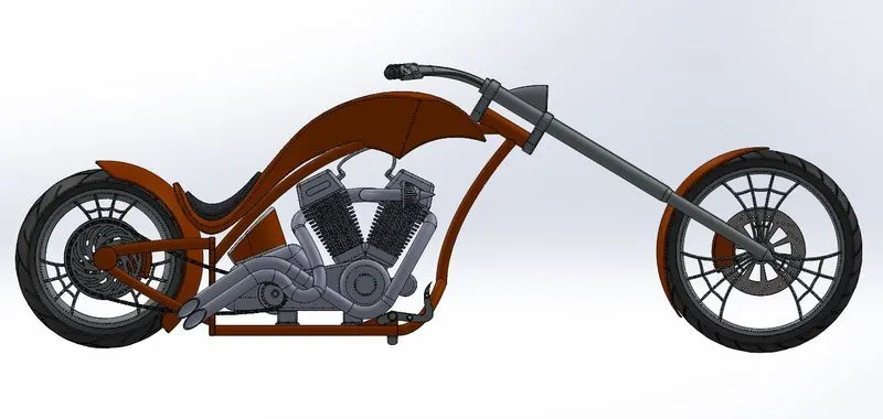
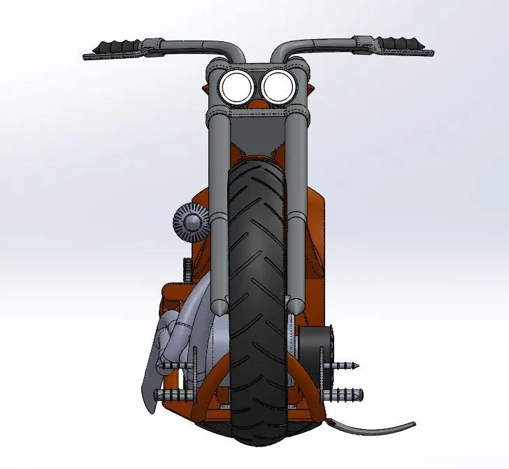
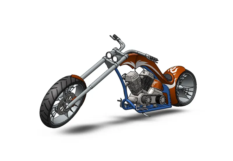
All the parts are constrained with respect to chassis. If error occurs / if there is problem with the part, it is modified as required to the assembly. An angle is applied to the kick stand (0 to 75 degrees) and front fork (-30 to +30 degrees). Carefull observation should be done at each step for the assembly to be fully defined and completed. The views of the complete finished assembly of the American chopper is shown below:
Before proceeding to the rendering part, a camera view is applied, because the render tool requires a camera angle to import the geometry.
5. Rendering of the Assembled Model
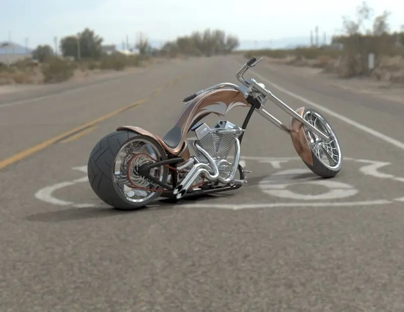
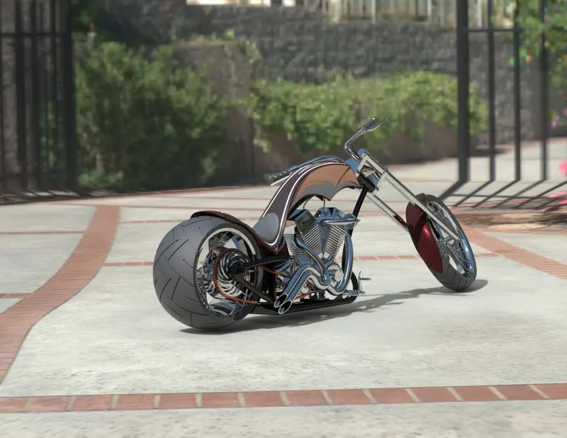
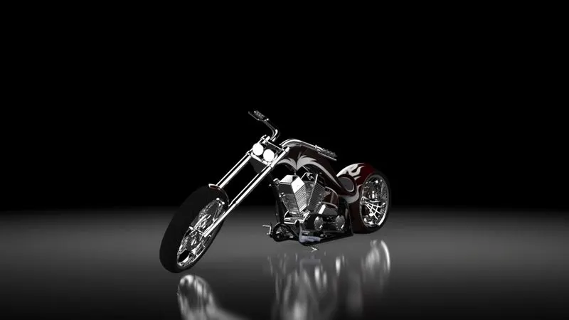
After the completion of the assembly od the chopper the complete model is the imported to the SolidWorks Visualize tool. Then the environment is changed to Route 66 and the model is centered along the Environment. The model view is adjusted as required an shown in below figure. Appearance of the components are changed to make the model look more realistic like the material is changed from Chromium plate to Chrome, Sienna to Anodized red, Chromium plate of fork to Anodized aluminium. The various views of the chopper when the environment is plain white is shown in below figures:
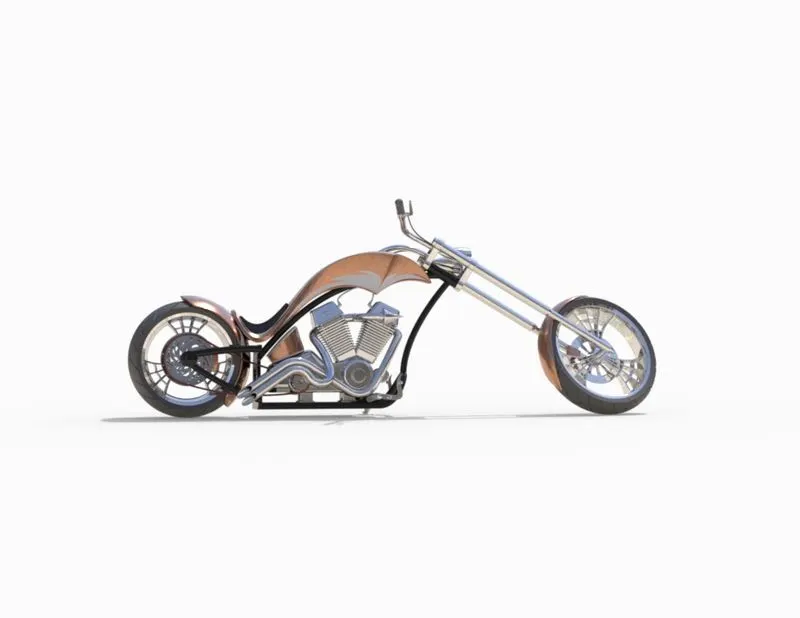
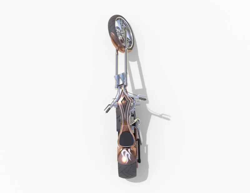
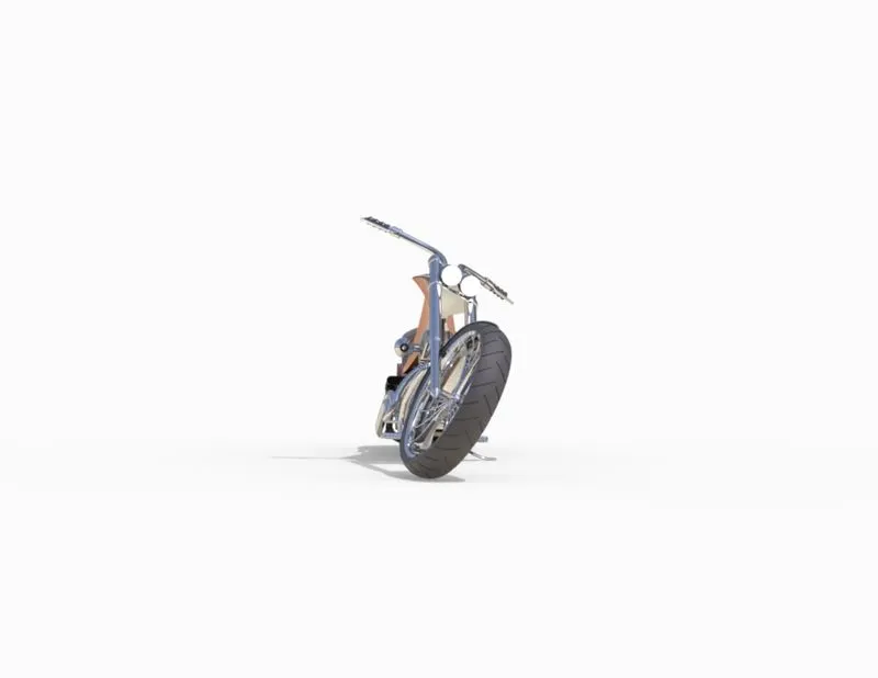
The Environment is then changed to Route 66 and the model orientation is adjusted to look more realistic. Also the brightness, shadow intensity is adjusted until a good natural look obtained. Whenever the brightness and shadow value is changed, fast render is done. Once the final almost perfect setting are done, accurate render is selected and proceeded. The frame is 932 x 720 and the reder passes is set to 3000. Atlast the final picture as shown below is obtained.
Same procedure is carried out and the Environment is then changed to Sunny driveway and the below final render pictuer is obtained.
6. Conclusion
Alll the features, tools and function of the Solidworks modelling and SolidWorks Visualize is understood.
The fully defined parts of the American choopper bike are modelled.
All the parts are assigned with appropriate appearances and assembled together carfully and perfectly with appropriate relations.
The assembled chopper bike is imported to SolidWorks Visualise and the orientation, environment, scenes and appearances are customised.
The final render obtained looks more realistics.