Wiring harness design in CATIA V5 - 3D modeling Week 2 Challlenge
Objective: The main purpose of this report is to understand the basic fundamentals of the Electrical Wiring Harness and also define the electrical connncetion to the connector and connnecter clip using Electrical Part Design Workbench in Catia V5
Introduction:
A Wire harness, also known as cable harness, wiring harness, cable assembly, wiring assembly or wiring loom, is an assembly of electrical cables or wires which transmit signals or electrical power. Commonly used in automobiles, as well as construction machinery, cable harnesses provide several advantages over loose wires and cables. Cable harnesses are usually designed according to geometric and electrical requirements. A diagram is then provided for the assembly preparation and assembly.
It can also be said the Wiring harness is the composition of Electrical and Mechanical CAD to connnect alll the electrical parts in the industries.
Environment Set-up:
First open the Catia V5 application. Under tool option select Customize.
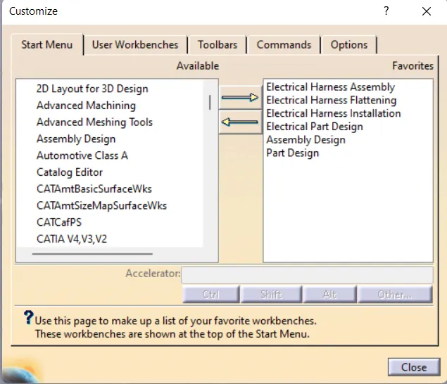
As shown in the above figure the required workbench are selected with is required for the Wiring Harness modelling in Catia V5.
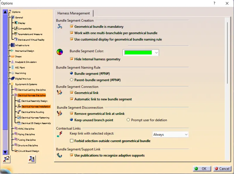
- Under the Tool feature select option and option window is opened.
- Infrastructure setting: The necessary cache management is enabled in product structure option.
- Equipment and system: Here in electrical mapping select the connector catalogue which was created.
- Electrical Harness Management
Models:
- Connector (Deutsch DT06 – 08SA)
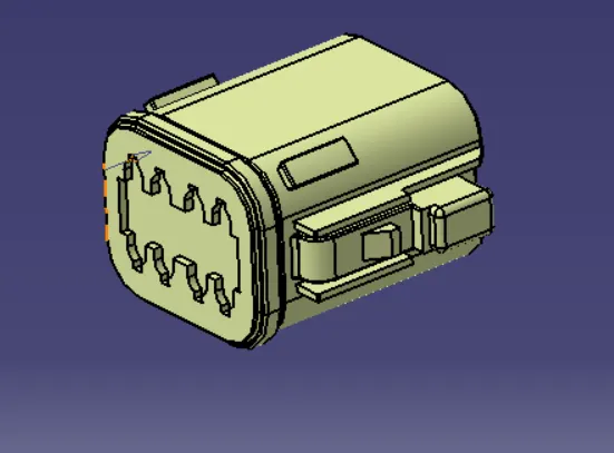
- First the part is downloaded from the required catalogue and saved.
- The part design workbench is opened and the connector file is opened.
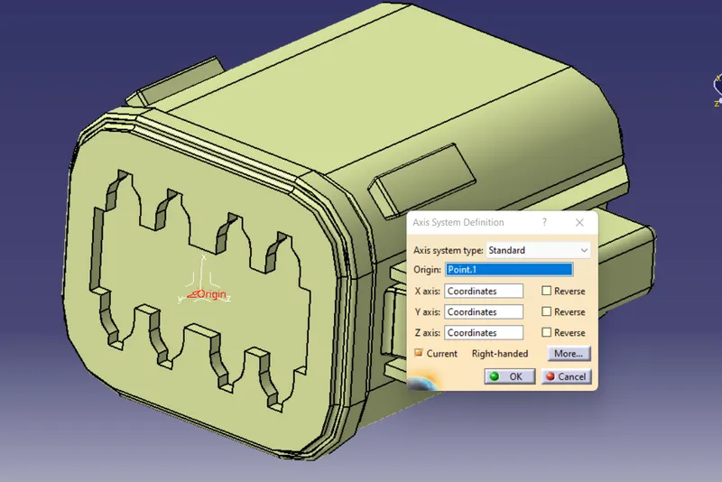
- Here the origin and orientation of the axis for the bundle connection and cavity connection is defined.
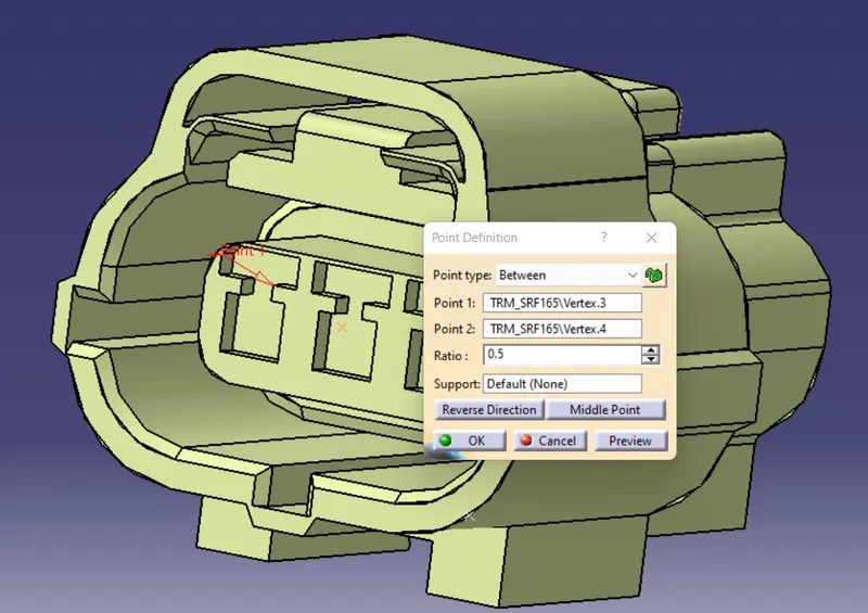
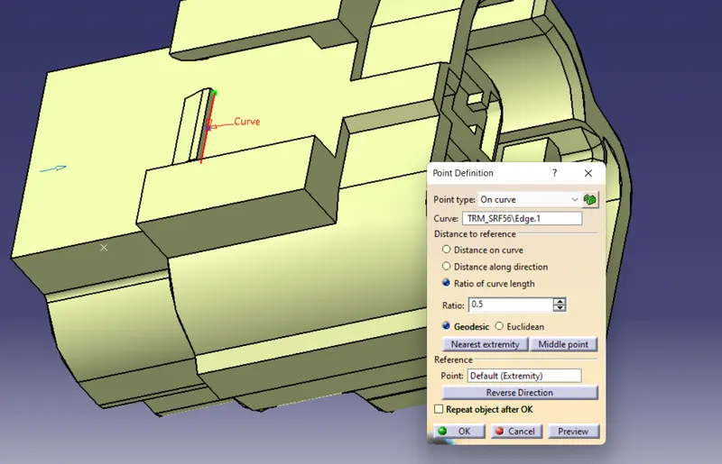
- First the point is created as shown below by using the midpoint option selectin two point and the orientation of the axis directions are given shown in below disgram.
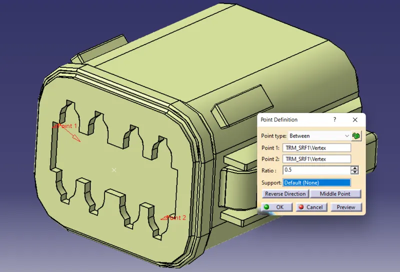
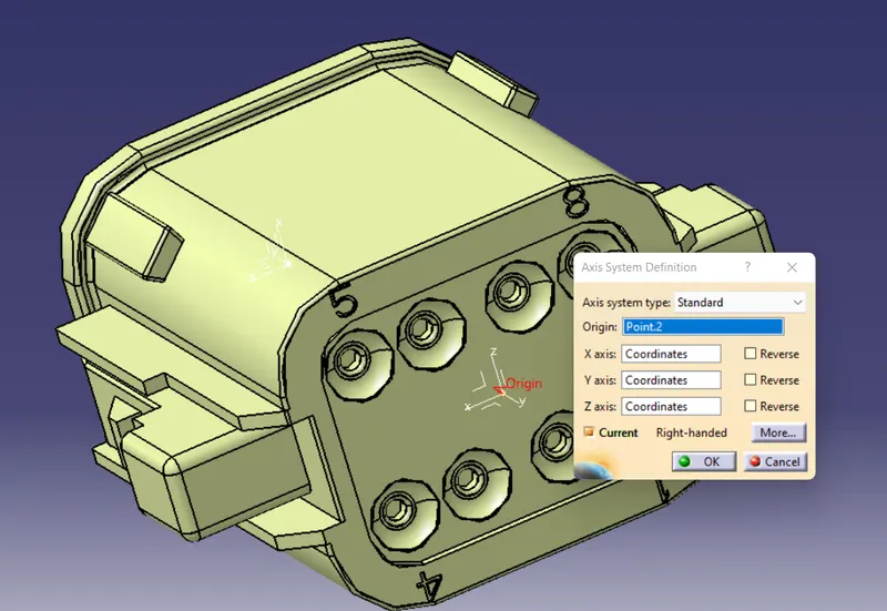
Same procedure is used on the other side of the conncetor and axis is defined.
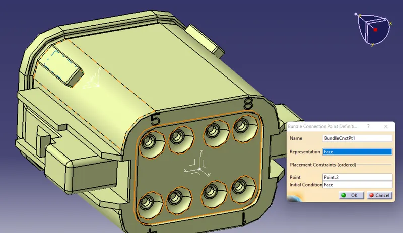
Now the part is shifted to electrical part design workbench.
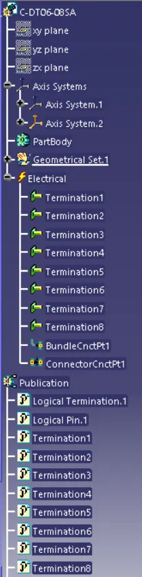
The whole body is defined as the connector. Now the bundle connection is defined at the point shown below:
- Connector Clip = Tyco 85229-1
In a same manner as above, the clip model is opened in part design workbench and the axis is defined as show below.
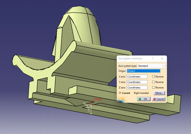
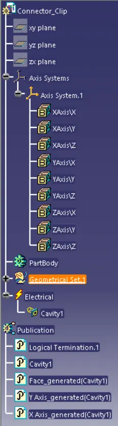
Next the workbench is shifted to electrical part design and her the Cavity connection point is defined as shwn below:
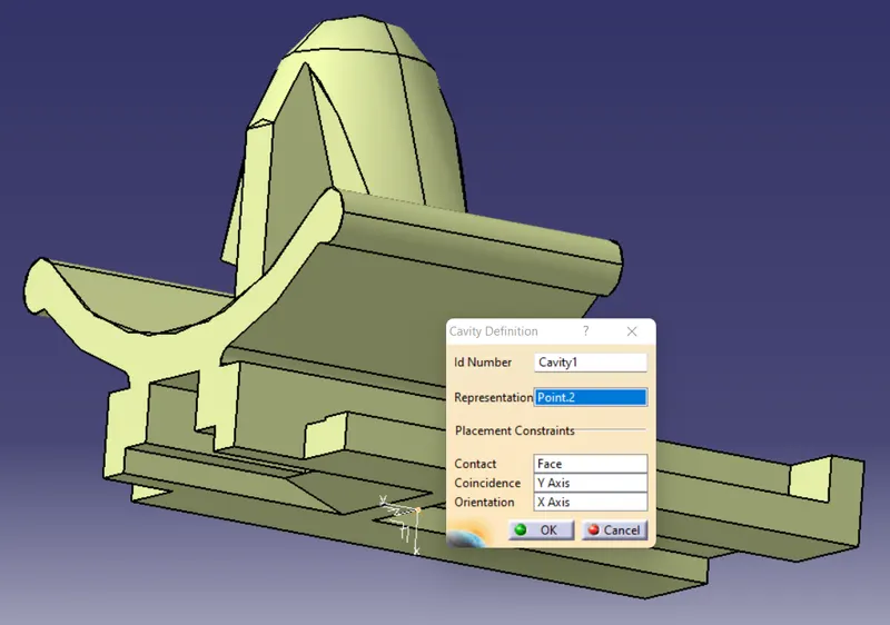
It has to be make sure that the axis orientation of the axis should be same as the axis provided to the connector.
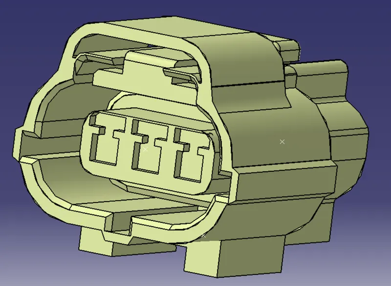
- Connncetor 2 = Tyco 174357-2
- First the part is downloaded from the required catalogue and saved.
- The part design workbench is opened and the connector file is opened.
- Here the origin and orientation of the axis for the bundle connection and cavity connection is defined.
- First the point is created as shown below by using the midpoint option selecting two point and the orientation of the axis directions are given shown in below disgram.
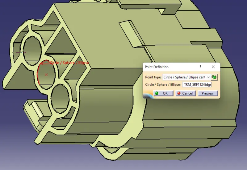
Axis definition and orientation should match the axis of the mating part.
Now the part is shifted to electrical part design workbench.
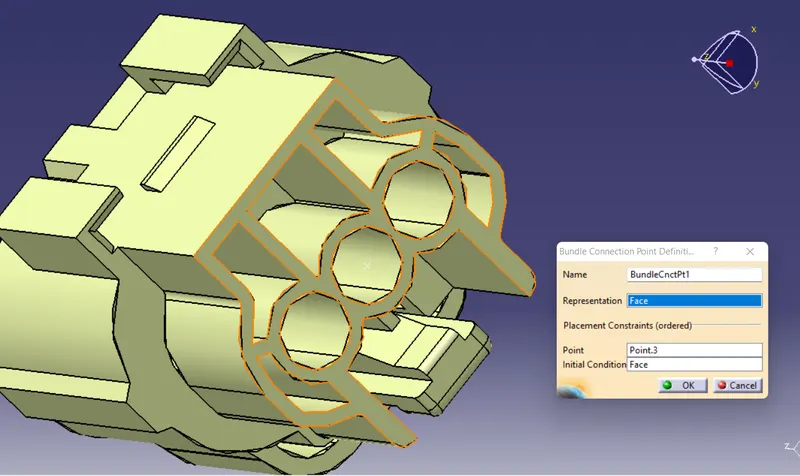
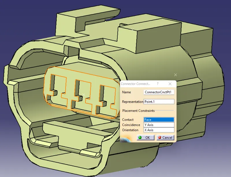
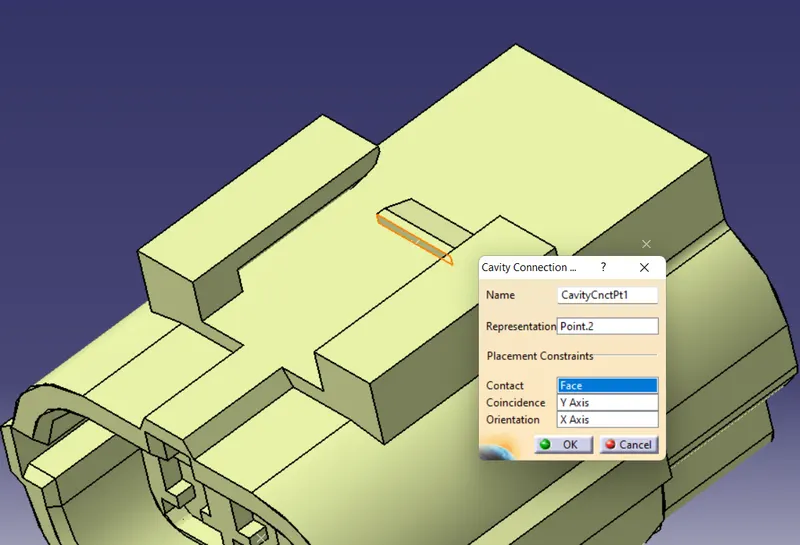
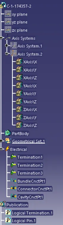
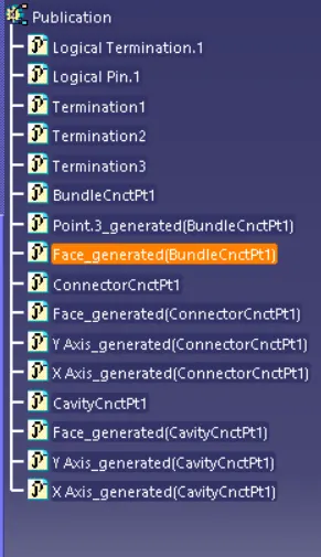
The whole body is defined as the connector. Now the bundle connection, cavity connection and connector connection point is defined at the point shown below:
Conclusion:
All the thre models are defined with the respective electrical properties such as Connector connection point, Bundle Connection point and Cavit connection Pont.
Thank You.