Wiring harness design in CATIA V5 - 3D modeling Week 4 Challenge
Aim: To Create as routing herness assembly between th connnectors using Electrical harness workbench in Catia V5.
Objectives:
- To create the route the harness layout using Electrical workbench in Catia V5 with given set of connnectors.
- To add the protective covering over the branches.
List of Connectors:
- DT06-4S
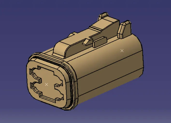
The cad part file is available and downloaded fron TE website.
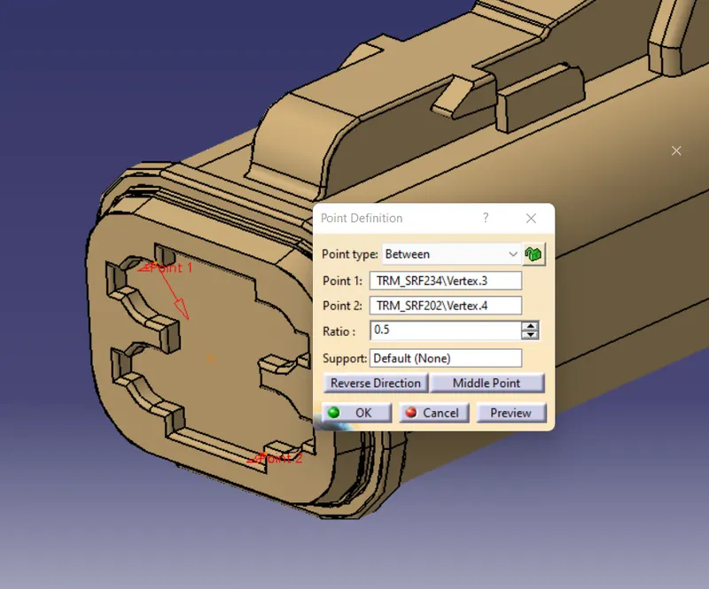
Now the file is opened in the Part design workbench. Now the point on the either side of the connector is created by selection between points as shown below.
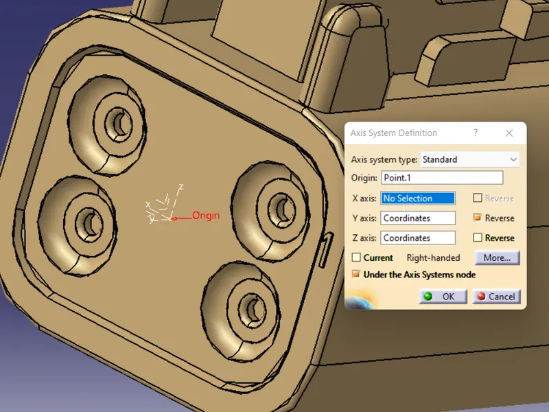
The axis is created as shown in above figure.
Now the model is transferred to electrical part design. The model is designed as connector (terminals 4). Now the one end point of the connector is defined with a bundle connection point.
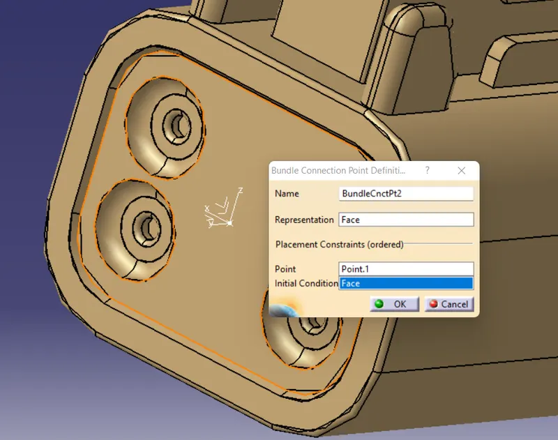
Now save the file.
Same procedure is followed to the other connectors.
- DT06-6S
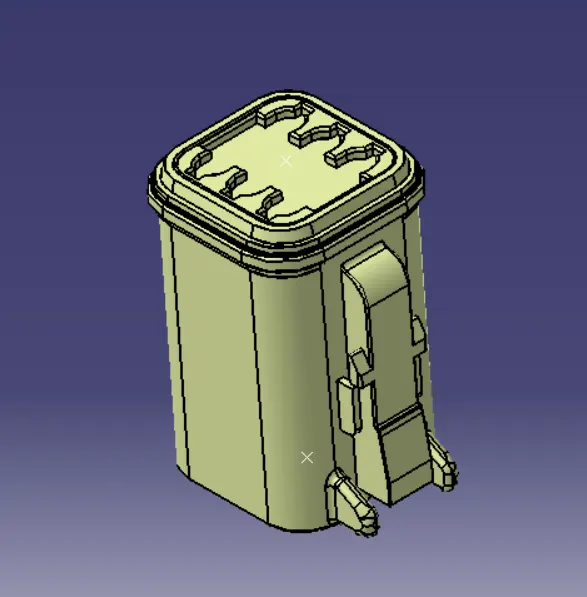
The cad part file is available and downloaded fron TE website.
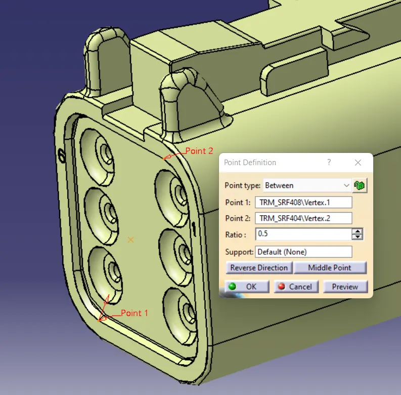
Now the file is opened in the Part design workbench. Now the point on the either side of the connector is created by selection between points as shown below.
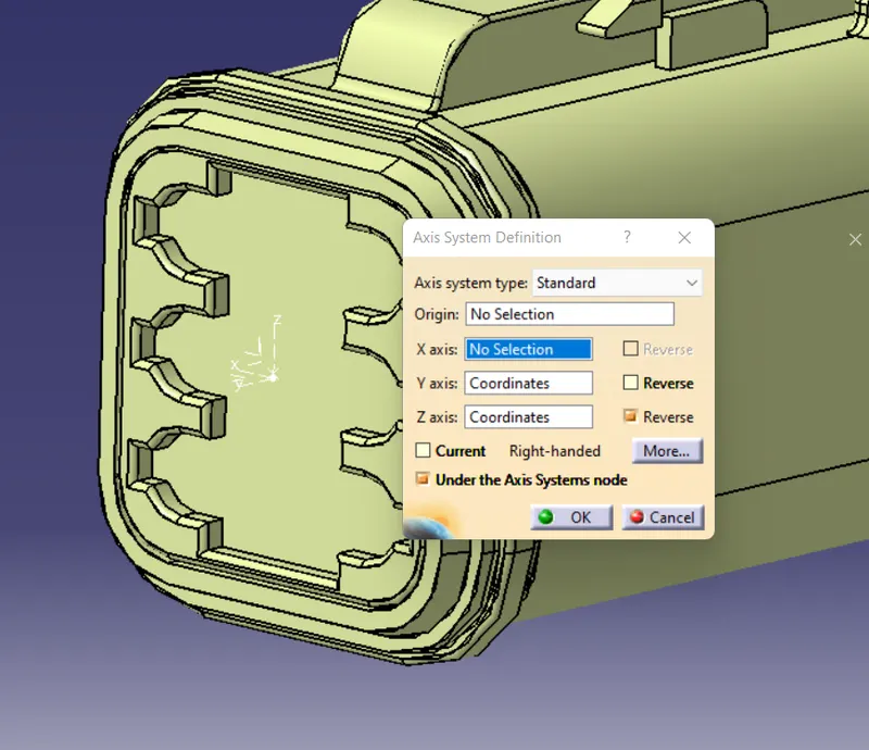
The axis is created as shown in above figure.
Now the model is transferred to electrical part design. The model is designed as connector (terminals 4). Now the one end point of the connector is defined with a bundle connection point.
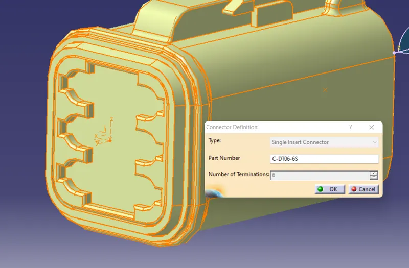
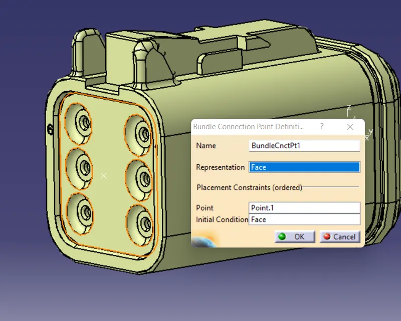
Now save the file.
- DT06-2S
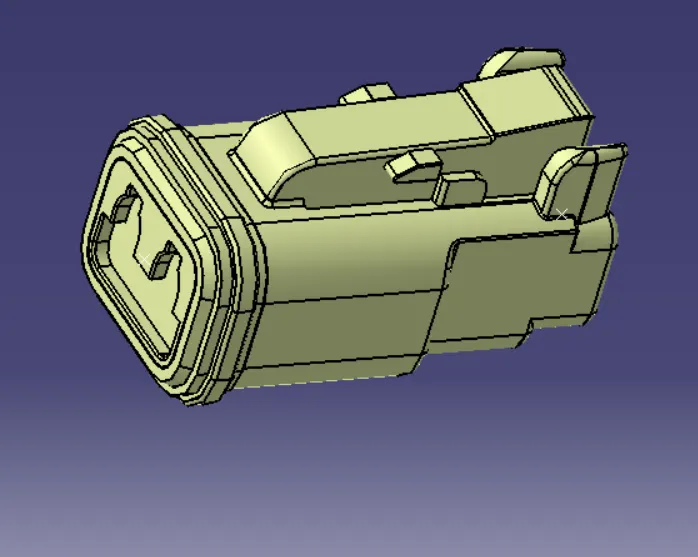
The cad part file is available and downloaded fron TE website.
Now the file is opened in the Part design workbench. Now the point on the either side of the connector is created by selection between points as shown below.
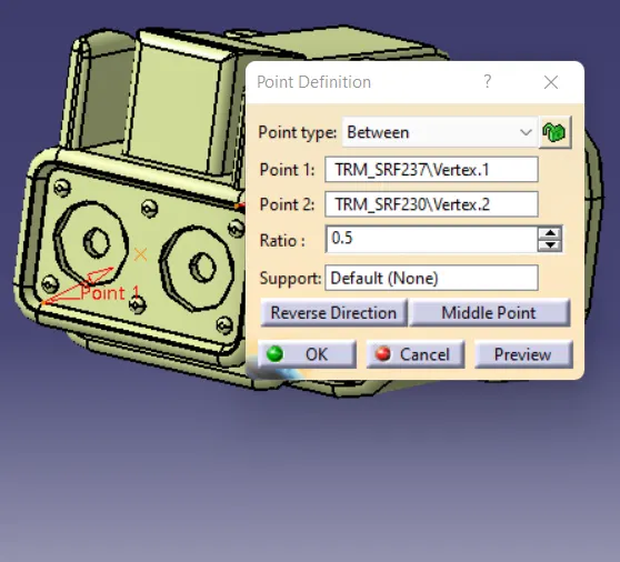
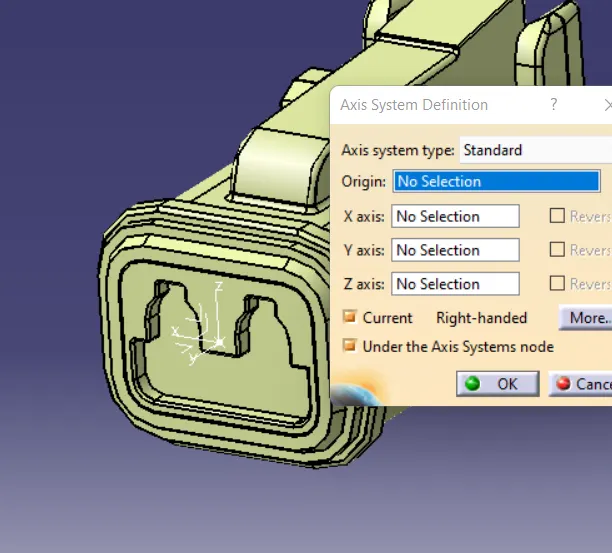
The axis is created as shown in above figure.
Now the model is transferred to electrical part design. The model is designed as connector (terminals 2). Now the one end point of the connector is defined with a bundle connection point.
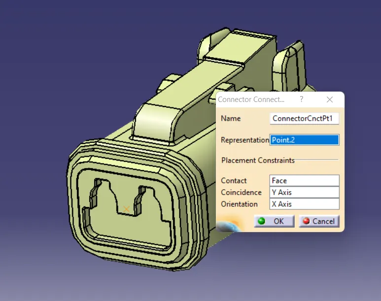
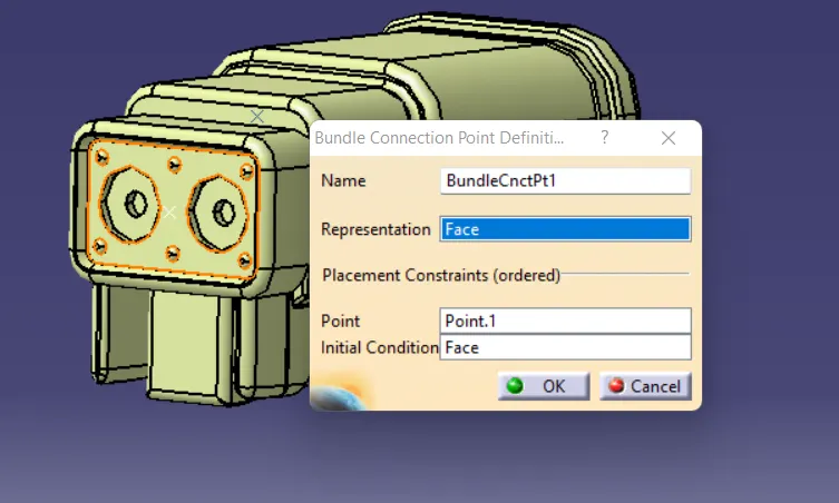
Now save the file.
- DT06-08SA
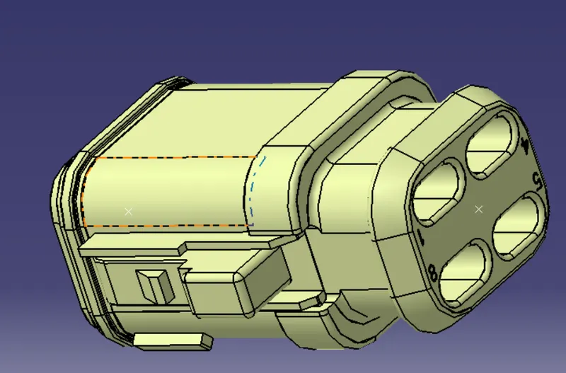
The cad part file is available and downloaded fron TE website.
Now the file is opened in the Part design workbench. Now the point on the either side of the connector is created by selection between points as shown below.
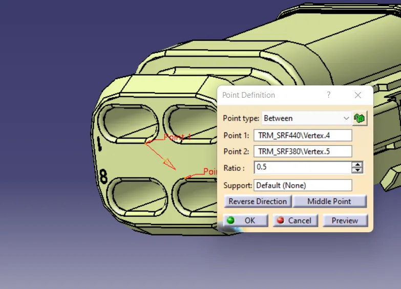
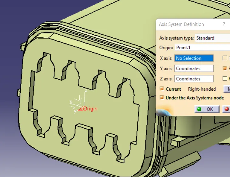
The axis is created as shown in above figure.
Now the model is transferred to electrical part design. The model is designed as connector (terminals 4). Now the one end point of the connector is defined with a bundle connection point.
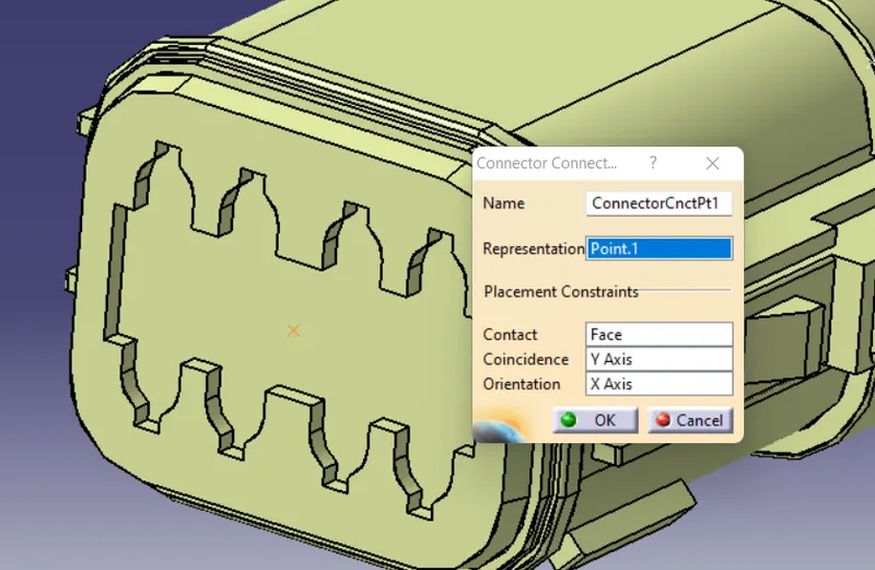
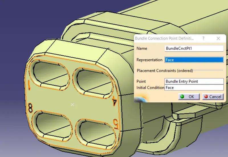
Finally save the file.
Electrical Harness Assembly
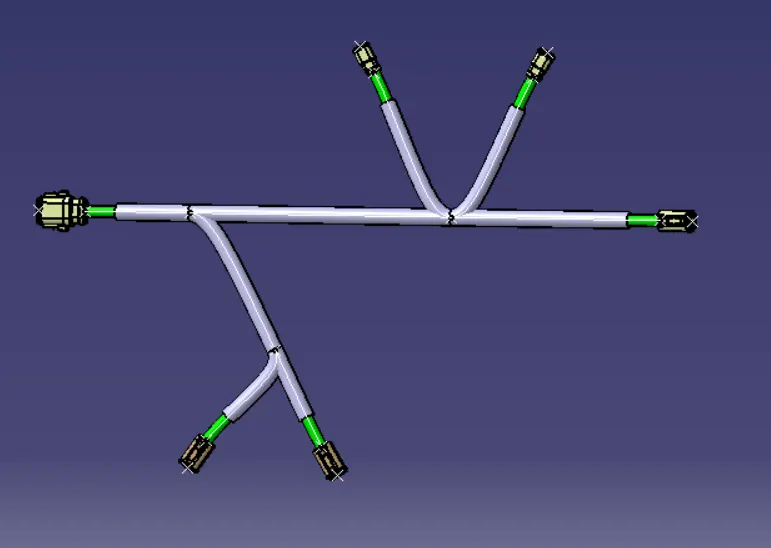
First we have to create a geometrical bundle in the electical harness assemble and then proceed with the next step.
To start with the electrical routing a reference metal plate is created which will used to align the cnnection at a appropriate positions.
the below figure was provided with dimensions.
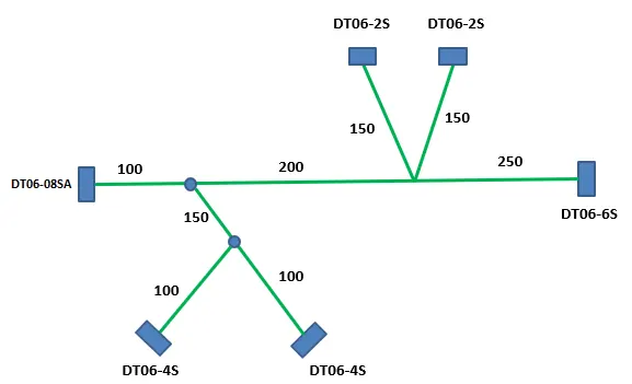
Wiht the help of this diagram group of line are drawn and planes are created on the metal plate in part design workbench as shown below.
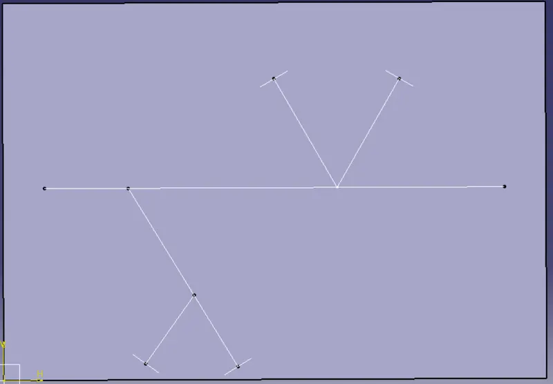
The distance and dimensions are same as the dimensions in the image provided.
Now the workbench is changed to assembly design and all the connector are imported one by one on their respective place using snap feature and making sure that the axis and orientation of the connectors are arraganged and matched to each ohter.
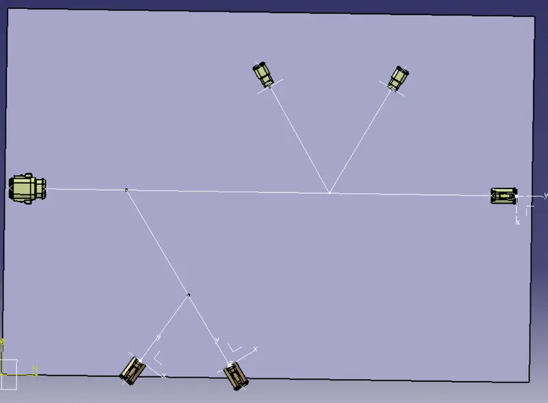
Hide the metal plate now.
Now the route is defined as required using clicking multibranchable document  and then clicking branch defination
 .
.
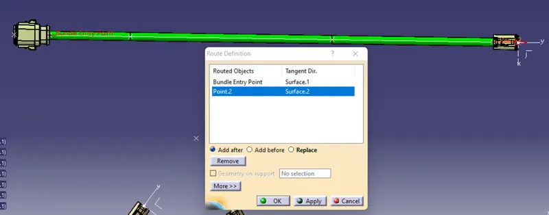
Appropriate diameter is taken and under route defination, the two connectors between which the branch has to be create are selected adn click OK.
Now the branch is created between the connectors ass hown below.
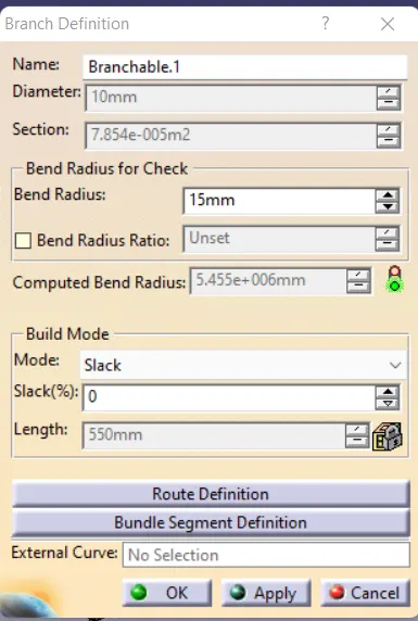
Now for the other branch to be created we have to create a branch point by clicking Add branch point  .
.
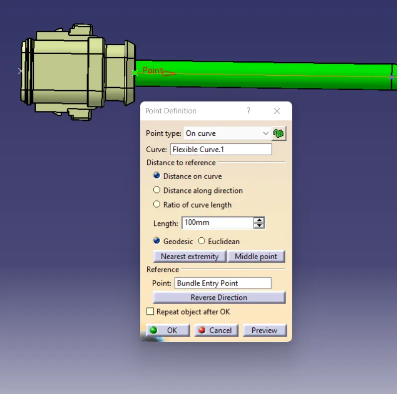
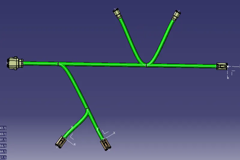
Once all the braches are created, the branches will look as shown below.
Next step is to add the protective covering over the routre bundles. Select protective covering option  and then the in the catalogue option we have to select the catologue where we have saved all the corrugated tubes.
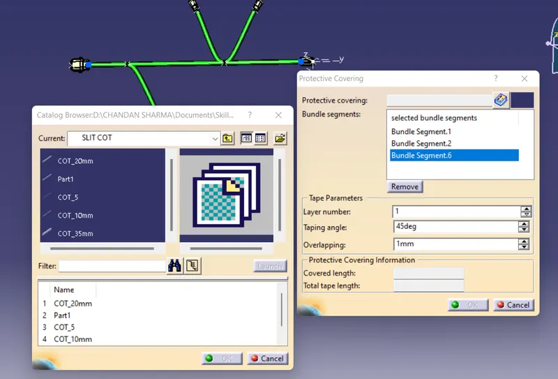
As described we have to keep the distance between the connectors and the tube with end explicit option of about 30mm to at the required places.
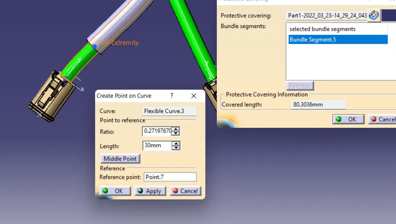
Similar procedure is carried out for all the branches.
Finally the complete routing harness is done as shown below.
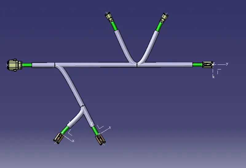
Last step is to save the file.
Hence, the routing harness is careted between the provided connectors adn harness layout.
Thank You.