Radar Mast & Final Assembly of Yacht
Modelling, Assembly and Rendering of Sunseeker Predator Yacht using Solid works.
Objective:
- To create a 3D model of invidual parts of Yacht.
- To assemble all the parts of Yacht together.
- To perform rendering of the Sunseeker Yatch using Solidworks Visualize.
1. Introduction:
Sunseeker Predator Yacht was manufactured by caompany named Sunseeker International - a British luxury performance motor yacht brand originally named Poole power boats. The yacht was used in popular James bond movie ( Casino Royale ) in 2006.
Sunseeker Predator Yacht modelling consists of 9 main components namely,
- Hull
- Superstructure
- Radar
- Radar mast
- Front Seat
- Middle Seat
- Rear Seat
- Garage Door
- Propeller
All these part are modelled as per the dimension provided and the complete tools / features are understood carefully before proceeding the modelling.
2. Medhology / Approach:
In this section, the process flow chart of the step by step procedure carried to comple the project is described as shown below:
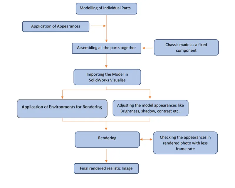
According to the application and instruction provided the material appearances are applied to the model. The parts are then assembled taking Hull as the fixed part and all the other parts are mated to it. After the completion of the assembly, the camera angle and directional lights are applied and the complete model is then imported to SolidWorks Visualise tool for rendering. The model appearance / scenes is adjusted and customised according to the respective environment and the final photo realistic rendered image is obtained.
Modelling
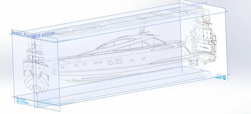
- Setting up Blueprint:
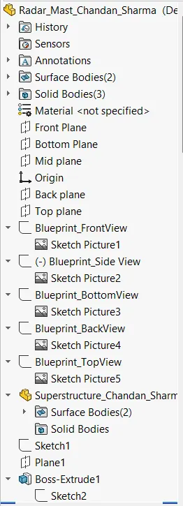
A blueprint is a guide for making something, it's a design or pattern that can be followed. The different 2D views in the form of images are imported in the design environment adjusting a required with respective planes. This help to create the model more accurately.
1. Propeller
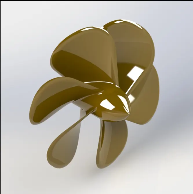
The Sunseeker yacht contains 3 propellers. Its is the main component of the ship or yacht without which it cannot move forward. The rotational movement of the propeller blades generates the flow of the water in the opposite direction which further helps in the movement of th yacht.
Features or Tools used:
- Line
- Arc
- Spline
- Circle
- Revolved Boss
- Circular Pattern
- Extrude Cut
- Filler
Procedure:
- Initially the center circular part is created using line, spline and revolve feature.
- Then single blade is created using Reference plane and lofted boss feature.
- With the help of circular pattern the required number of blades are obtain by selecting any on circular edge as guide curve.
- Atlast, aapropriate appearance is added to the model as required.
2. Radar
Radar is a vital navigation component for safety at sea and near the shore. It is a electronic navigation instrument that use a rotating antenna to sweep a narrow beam of waves around the water surface detecting targets by microwaves reflected from them, generating a picture of the ship's surroundings on a screen.
The small boat radar is supposed to be mounted at the highest point of the boat, where it will not be obstructed for utmost efficiency. Also, installing it at the highest point of the boat prevents people from being exposed to the waves being emitted by the small boat radar.
Features Used:
- Line
- Arc
- Spline
- Exrtude Boss
- Fillet
- Mirror
- Split
- Appearence
- Add Text
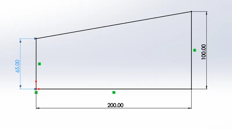
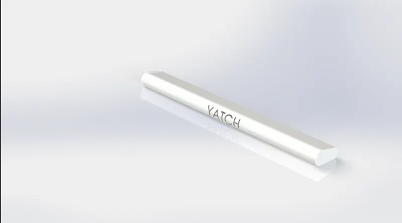
First draw the above sketch the body of the Radar and then extrude boss was used to give the depth. By using the Sketch Pattern the four Dotted holes were drawn anad using Extruded Cut the holes were created. The Radar has a circular slot / hole underneath which was created using Extrude cut feature by drawing a circle.
The other half was mirrored with the help of mirror feature tool. The Text over the Radar was created using the Text option in sketch entities and then the Split Line was used to add it. At last the radar should be filleted around the edges of the body and also around the edges of the holes.
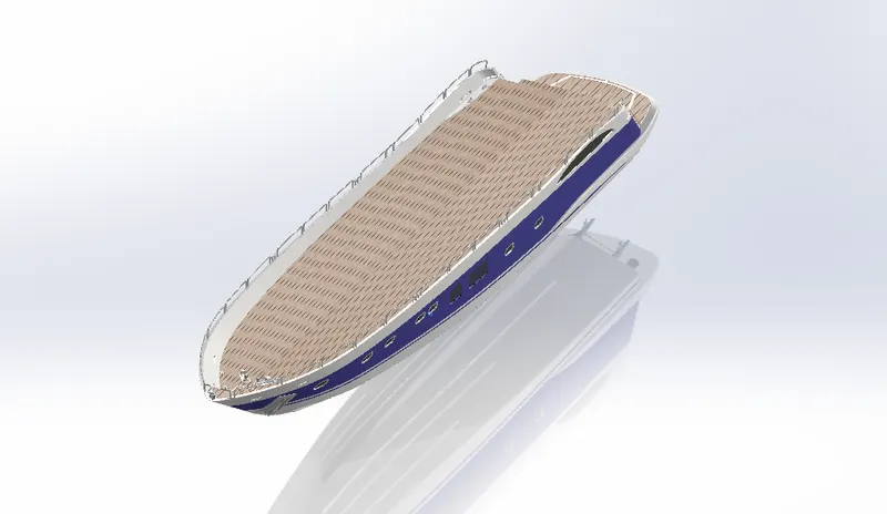
3. Hull
The main body of a boat is called its hull which floats on the water surface. The line where the hull meets the water surface is called the waterline.
Features used:
- Line
- Arc
- Spline
- Circle
- Exrtude Boss and Revolve
- Extrude Cut
- Dynamic mirror entities.
- Fillet
- Mirror
- Split and Split Line
- Comsume and save bodies
- Appearence
- Edit Decals
- Offset
- Projected curve
- Reference Curve
- Edit Deacal
- Appearances
Before starting any kind of sketch, the blueprint file created shown in above section is imported which is very important thing to do. With the help of all the bluprint views the sketch are drwan usign spline and line command. The spline curvature is matched to the curvature of the blueprint by adjusting the arroe os the respective spline.
Using Lofted boss and fill tool wherever neccesary accordingly the surface was create. Making sure that all the surface are knitted and merged together carefully. Projected curve were used were there is need od a smooth curve away fron the planes and curves are then connected by creating a reference plane and 3D sketch tool.
The windows are created by sketching on the mid plane and then using extrude feature and slecting offset fron the surface. The surface is then selelcted and the offset distance is given. Rails are then created ba a series od lines connected and using the projected curve to get the sketch on the required place, then creating circle at end of the lins and sweep across the curve. Using All these features and tool, the hull is is created.
Split too is used to created a divide a surface on to different parts by creating a required sketch line on the surface and selecting it as a split tool.
The upper flat surace is offseted with thickness zero and offset distance zero for the reference of the other part such as Superstructure. Then the decals are added by enabling the photoview 360 option in add-ins and choosing required decal from the library. Atlasrt the appearances are added to the Hull parts as required with respective colours.
4. Garage Door
Features Used:
- Line
- Arc
- Spline
- Exrtude Boss
- Fillet
- Mirror
- Split
- Appearence
- Add Text
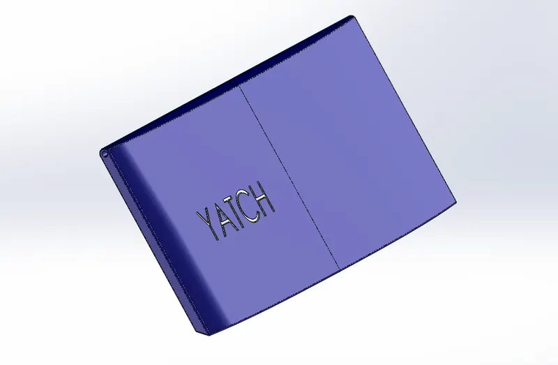
First draw the above sketch the body of the Radar and then extrude boss was used to give the depth.The other half was mirrored with the help of mirror feature tool. The Text over the Radar was created using the Text option in sketch entities and then the Split Line was used to add it. At last the door should be filleted around the edges of the body and the decals, appearance are added accordingly as required from the library.
4. Rear Seat , Front Seat and Middle Seat
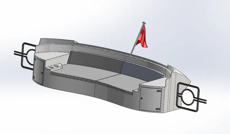
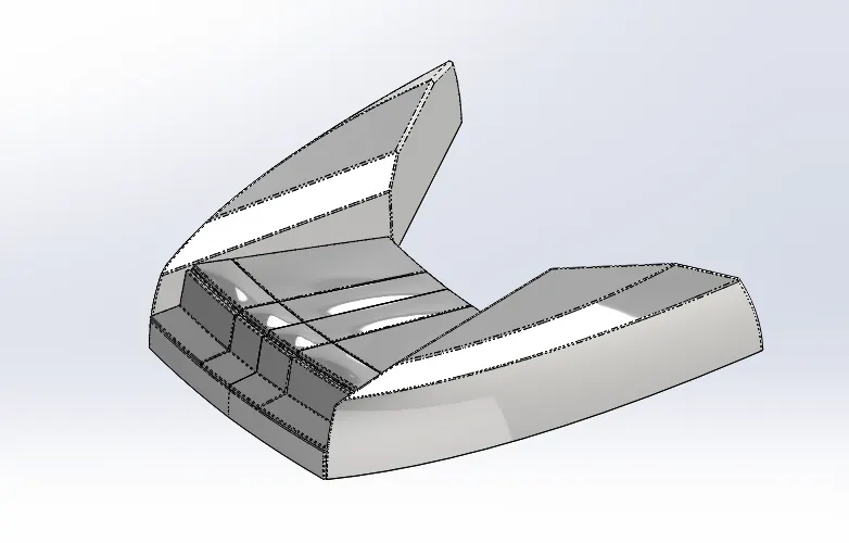
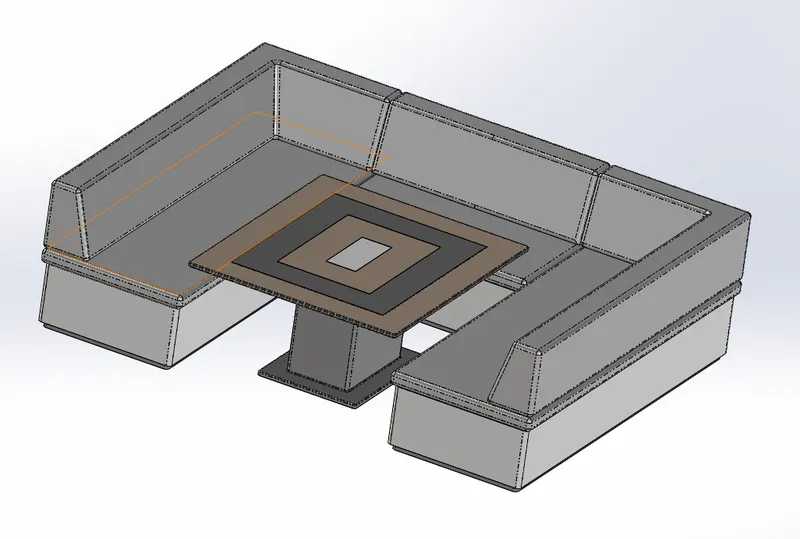
Seats are modelled either by solid features or by using surface features There are three seatings in the model-Front, Middle and Rear
Here, the Front and the Rear seats are modelled by first creating the outer surfaces using the features of the Surface tab such as Lofted surcae, rulled surace and Trim surface. Then creating a solid after carefully knitting the surfaces together using the Knit Surface feature. The red flag shown below is drawn using 3D sketch and the with the help of Fill surface the required flag is created.
- Rear Seat
- Front Seat
- Middle Seat
Features Used:
- Line
- Arc
- Spline
- Circle
- Convert Entities
- Exrtude Boss and Revolve
- Extrude Cut
- Extrude Surface and Cut Surface
- Lofted Surface
- Knit Surface
- Dynamic mirror entities.
- Fillet
- Mirror
- Split and Split Line
- Comsume and save bodies
- Appearence
- Edit Decals
- Offset
- Projected curve
- Reference Curve
- Edit Decal
- Appearance
Atlast, the decals and the appearance are added accordingly as required from the library.
5. Superstructure
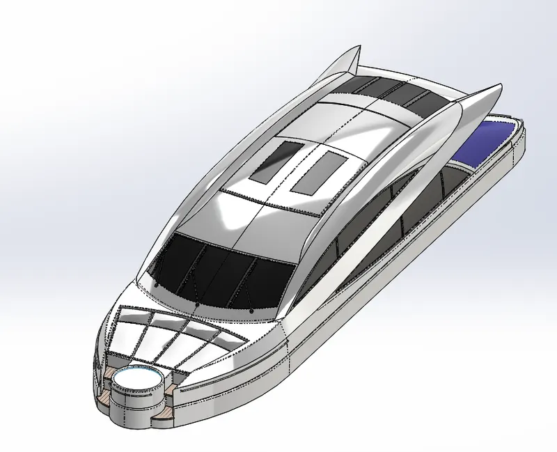
A superstructure is an extended construction of any building or platform that rises above the rest of the building or platform in a distinct manner. They are designed in a manner, so that, they add value and hinder the speed and mobility in the least. The superstructure is mostly designed in fashion as well. This is because it is the most easily visible part of the ship, in fact it is the identification of the ship, and so the designers try to provide it with the identity that is unique
Features Used:
- Line
- Arc
- Spline
- Circle
- Convert Entities
- Exrtude Boss and Revolve
- Extrude Cut
- Extrude Surface and Cut Surface
- Lofted Surface
- Knit Surface
- Dynamic mirror entities.
- Fillet
- Mirror
- Split and Split Line
- Comsume and save bodies
- Appearence
- Edit Decals
- Offset
- Projected curve
- Reference Curve
- Edit Decal
- Appearance
On water craft, the superstructure consists of the parts of the ship or a boat, induding sailboats, fishing boats, passenger submarines, that project above her main deck ships, and This does not usually include its masts or any armament tunets.
Here, the Superstructure is also modelled by creating the outer surfaces first, just as we did in the case of Hull. Once the surface is enclosed front all the ends it is converted to solid. If there the is any blue edges, then error will arise and solid will not be created. So, carefully all the edges are checked carefullly and if there is any blue edge it is then propered and then solid is created. Make sure all the surfaces are knitted to geted prperly.
The solids are then mirrored using the Mirror command and then knitted together properly with the Knit Surface.
Here as well, the things are modelld by using the Swept Boss/Base feature.
The jacuzzi is just a cutout with a surface at the top to represent the water level. The surface is given a transparent appearance for this purpose
The window edges are blended using the Fillet feature to give a smooth appearance.
The vipers are modelled using solid features such as Extruded Boss/Base, Extruded Cut Swept Boss/Base, etc. along with appropriate Chamfers and Fillets.
6. Radar Mast
A mast is a vertical ship structure mounted on top of bridge and forward of the forecastle towards the ship's bow. It accounts for the support platform for the ships demick and hold necessary equipments such as radars, navigation light and ships hom in case of foremast. The main job of mast is to hold necessary equipment such as radar receiver, navigation lights, ships hom, flags and demicks in some case.
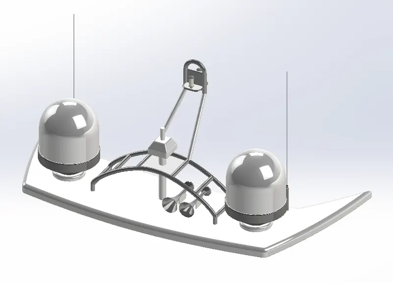
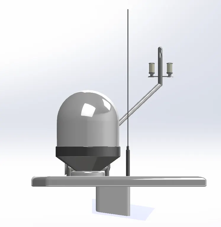
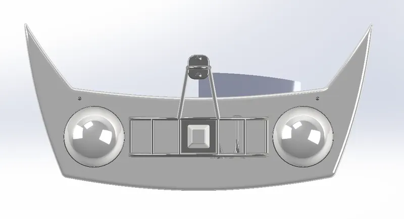
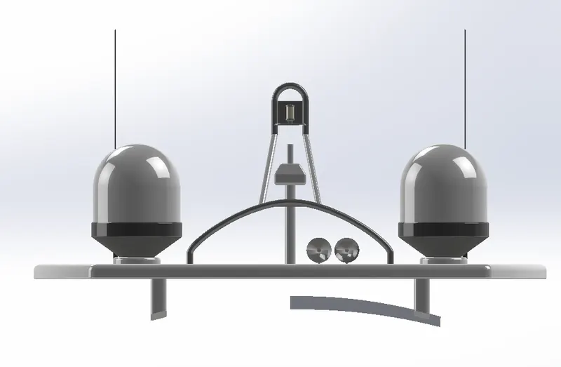
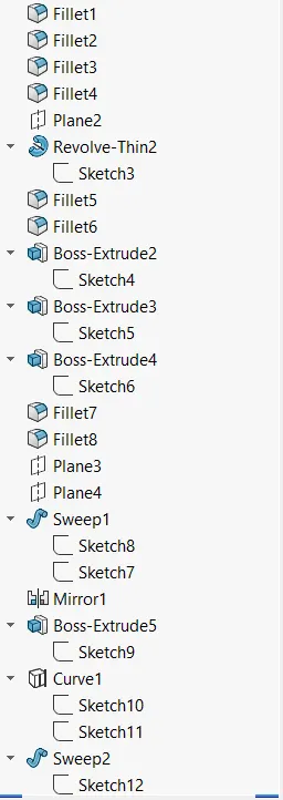
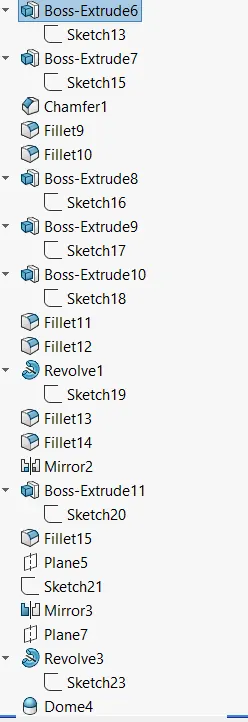
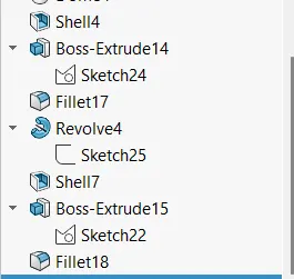
The first half of the Radar was Modelled with the help of blueprint and then the other half was minored with the help of
Mirror tool The body of the Radar was created using Extruded Boss/Base and Revolved Boss/Base.
The antenna for the radar was also created using the Extruded Boss/Base. The lamp stand along with the connecting rod were created using the Swept Boss/Base and Mirror tool.
The lamp is created by using the projected curve and then the curve was swept using swept boss/base
The homs were created using the Revolved Boss/Base, Dome and Shell
Then the fillets and chamfers were applied wherever necessary.
7. Assembly of Yacht
The first component selected for assembly is Hull and this is made a fixed compent. Then all the parts are inserted in a order shown below:
- Hull
- Front Seat
- Superstructure
- Middle Seat
- Rear Seat
- Garage door
- Propeller
- Radar Mast
- Radar
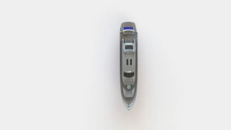
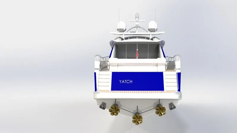
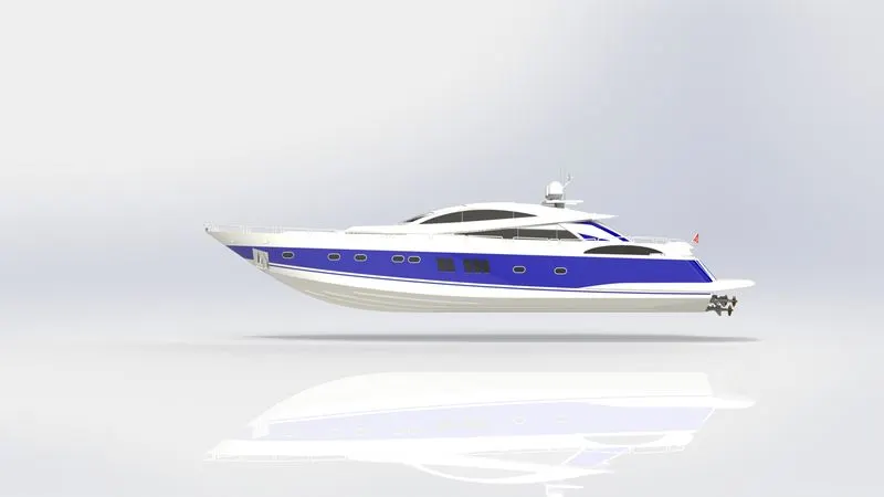
All the parts are constrained with respect to Hull. If error occurs / if there is problem with the part, it is modified as required to the assembly. Carefull observation should be done at each step for the assembly to be fully defined and completed. Here the radar and propeller will be rotating parts, so they are not fixed by orientation. The views of the complete finished assembly of the American chopper is shown below:
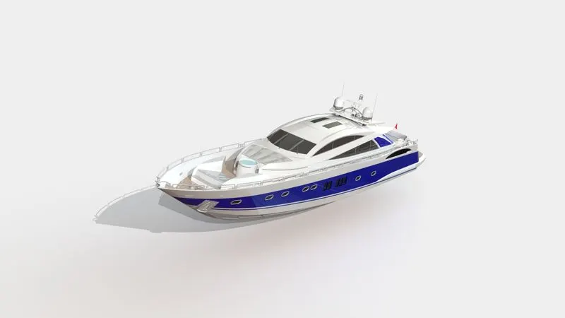
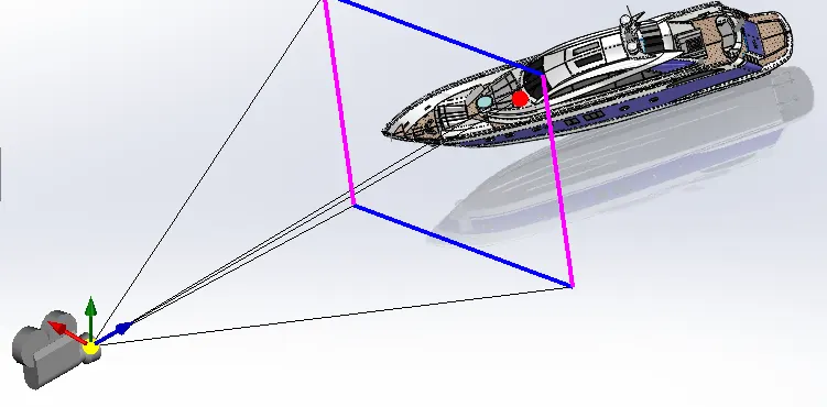
Camera setup view for proceeding the rendering is shown below:
8. Rendering
After the completion of the assembly od the chopper the complete model is the imported to the SolidWorks Visualize tool. Then the environment is changed to Ocean and the model is centered along the Environment. The model view is adjusted as required an shown in below figure. Appearance of the components are changed to make the model look more realistic.
Also the brightness, shadow intensity is adjusted until a good natural look obtained. Whenever the brightness and shadow value is changed, fast render is done. Once the final almost perfect setting are done, accurate render is selected and proceeded. The frame is 932 x 720 and the reder passes is set to 1500. Atlast the final picture as shown below is obtained.
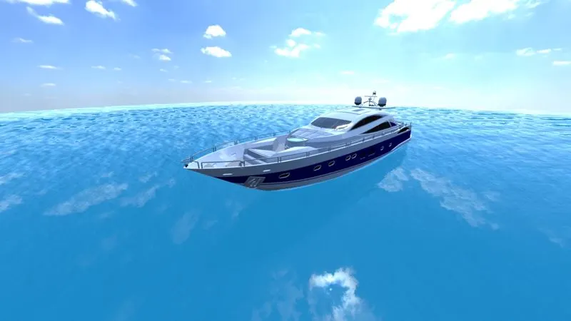
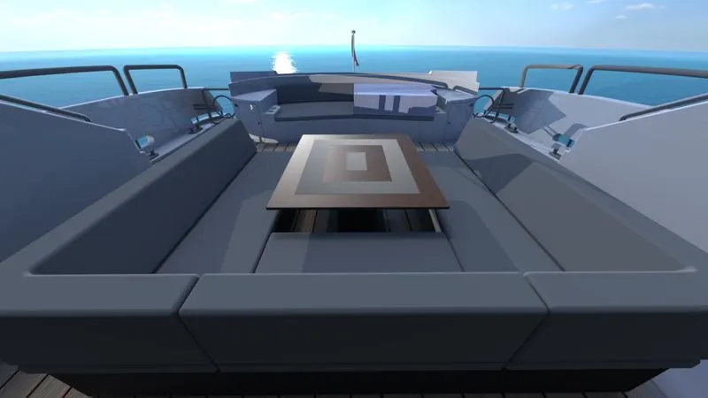
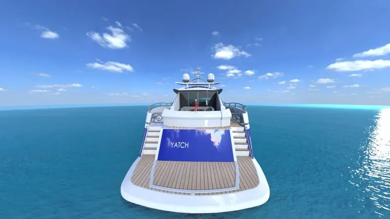
Same procedure is carried out and the Environment is then changed to Marine bay and the below final render pictuer is obtained.
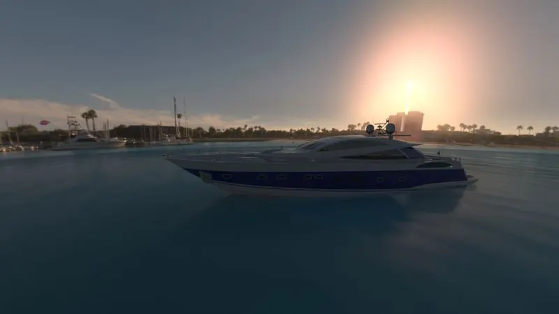
Conclusion:
Alll the features, tools and function of the Solidworks modelling and SolidWorks Visualize is understood.
The fully defined parts of the Sunseeker Predater Yacht are modelled.
All the parts are assigned with appropriate appearances and assembled together carfully and perfectly with appropriate relations.
The assembled chopper bike is imported to SolidWorks Visualise and the orientation, environment, scenes and appearances are customised.
The final render obtained looks more realistics.