Wiring harness routing & packaging Rules Week 3 Challenge
Objective: The main purpose of this report is to understand the basic fundamentals of the Electrical Wiring Harness and also define the electrical connnection (support) to the Clamp and backshell using Electrical Part Design Workbench in Catia V5.
1) P Clamp:
A P clamp or also known as pipe clamp is a type of clamp often employed in woodworking, piping or cabinet shops.
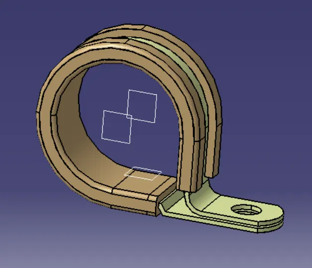
Steps:
- First the part file is downloaded from the required catalogue and saved.
- Now for the clamps here a total of 3 planes has to be created ( one on the either side and other the base plane.
- Now a point is created at on side by selecting the circular profile as shown in below figure and activating the circle center arc.
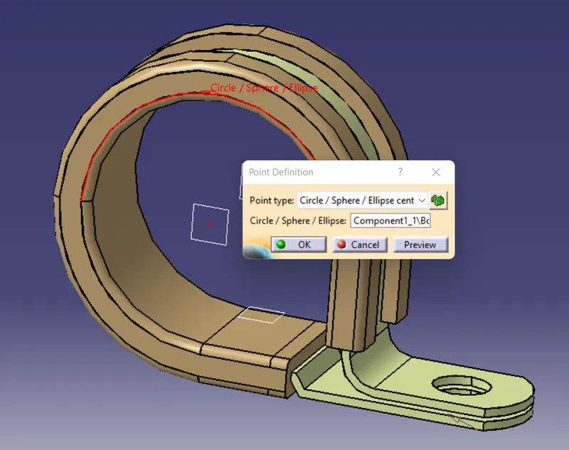
- Similary, the point on th other side of the clamp is created.
- Now, the planes are created one by one selecting the points and making sure that paralled through point is selected as shown below. The end flat surface is selected as the reference.
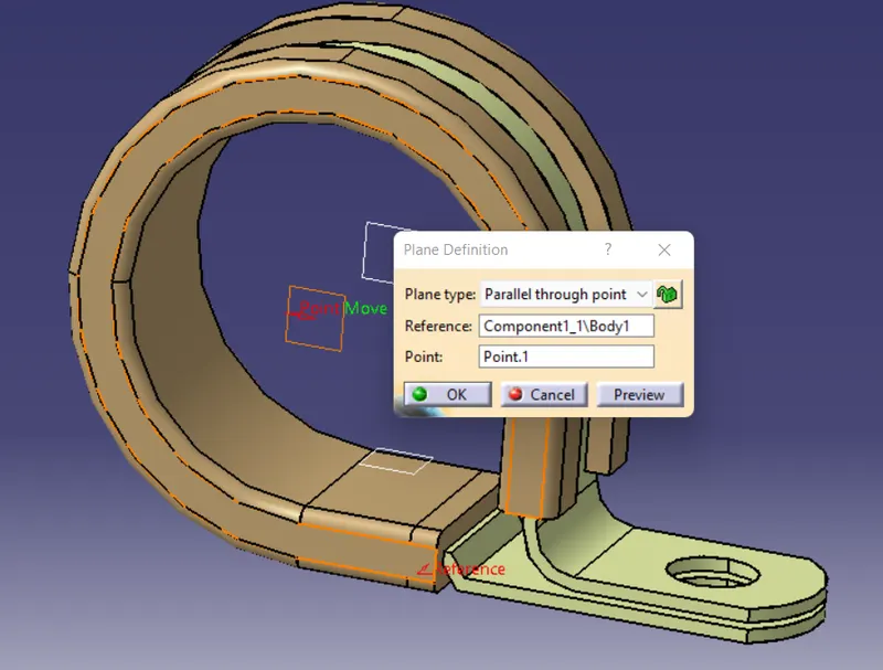
- Once both the planes on the either side are cerated, next base plane is created by selecting offset from surface by 2mm and selecting the flat face as shown in below figure.
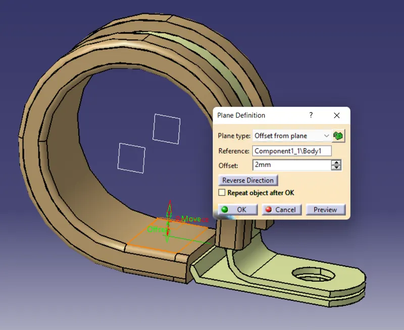
- Next step is to define the electrical supports.
- The workbench is changed to Electrical part design.
- Now click define support
 and select the clamp part body. Then select point 1 and respective as first plane defination, then other plane and base plane.
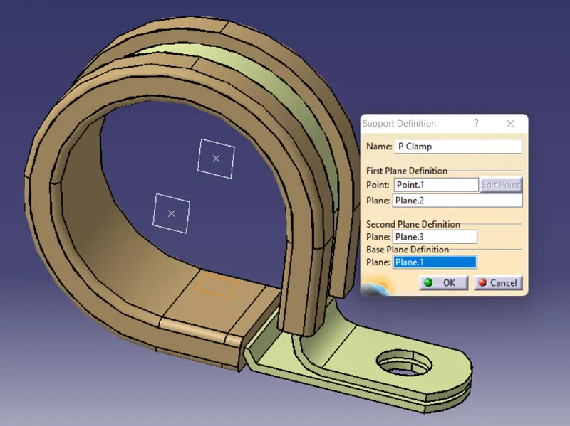
- After this the first point will disappear which means it is not availabe for further support of the that point.
- Similar procedure is followed for the other side but here after selecting the first plane defination the second plane is auto assigned the same plane, because the other plane was already used.
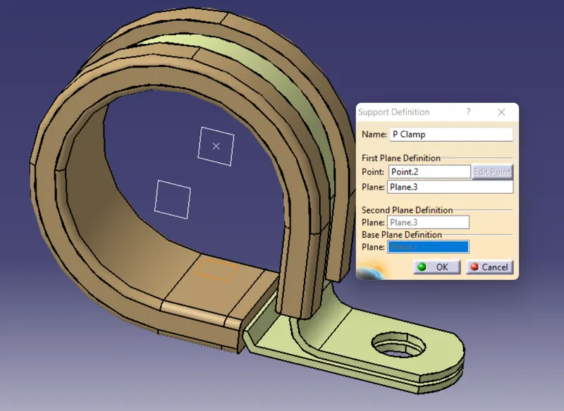
- Now all the supports are porvided to the p clamp and the file is saved.
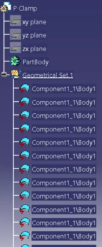
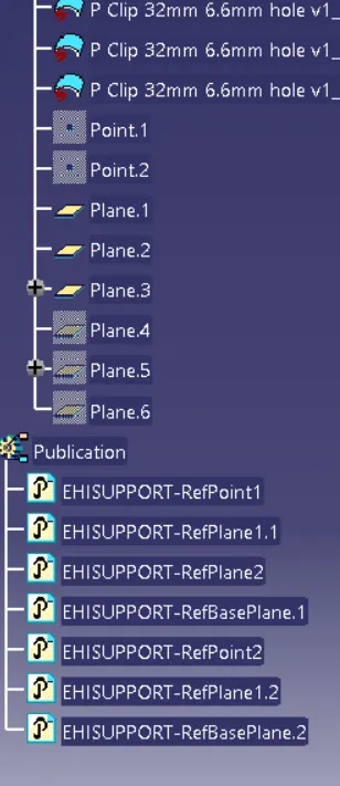
Design Tree:
2) Backshell (Tyco 1738312-1)
A backshell is a mechanical device threaded into the rear of an electrical connector.
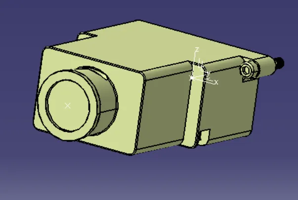
- Here a rectangular backshell as instructed ad provided is downloaded and saved.
- Initially, mechanical part design workbench is activated to define th epoints and axis.
- First the point is created on the rectangular face side of the backshell.
- The between option is clicked and two diagonal ends of the rectangular face is selected and using the midpoint th epoint is craeted as shown below.
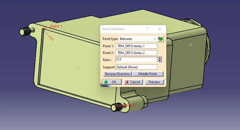
- Similarly the point is created on the other side, by selecting circle center option.
- Next step is to create the axis.
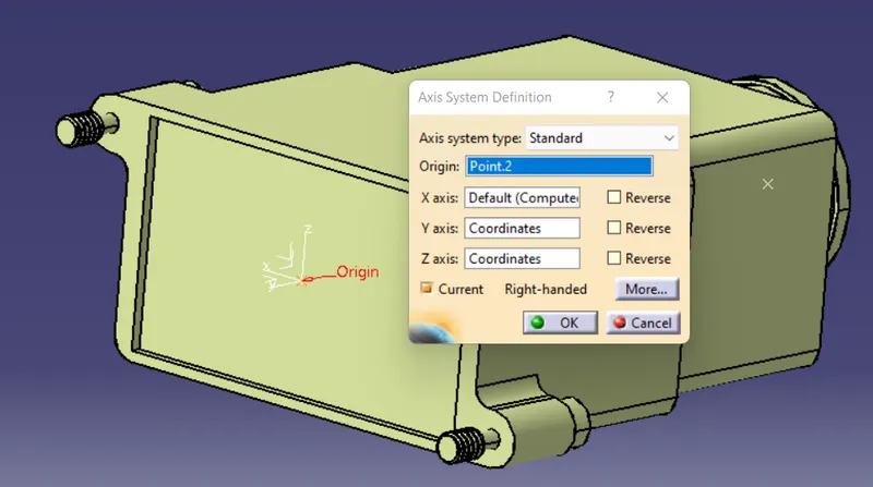
- The point on the rectangular side is selected for axis definition.
- The x-axis is rotated to 90 degrees, makeing sure that the z-axis is towards the top, y-axis is on the direction of connection and x-axis on the left side.
- Now the workbench is changed to electrical part design to define the electrical connections to the backshell.
- The part body should be defined as the backshell first. For this define backshell
 option is clicked and the part body is selected.
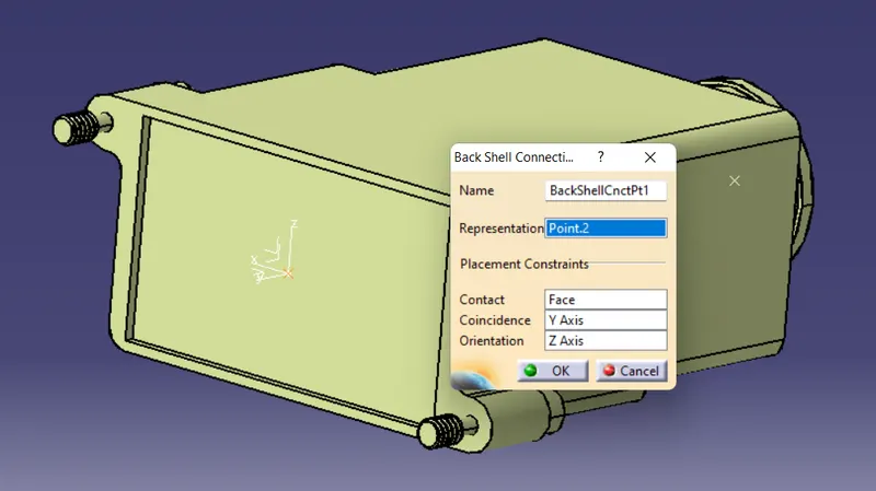
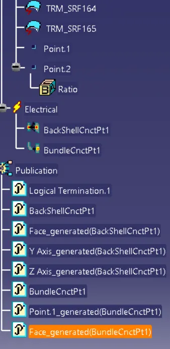
 - Next the backshell connection point
 is clicked and the body is selected.
 - The point on which the axis created is selected and other parameters are selected as shown below.
- Next the bundle connection point
 option is clicked to define the bundle connection on th eother end of the backshell as shown below.
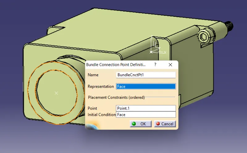
Since all the connnections are defined the file is saved.
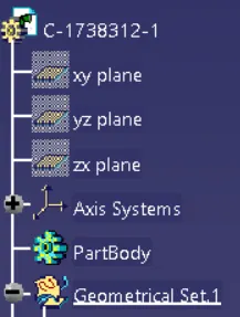
Design Tree:
3) Corrugarted tubes
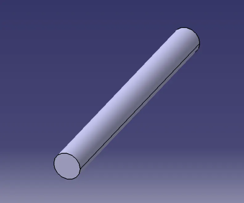
Corrugated pipes or tubes are used where flexibility is an important factor other than strength and durability, such as in storm drains and culverts. Flexibility makes corrugated pipes more useful and suitable for a wide variety of uses.
The are used as the protection the electrical wire from external contact or damage.
Procedure:
- The electrical part design workbench is selected first.
- Now, define protection part
 option is clicked and part body fron the design tree is selected.
 - Next, in the small window appeared the input diameter, thickness and the bend radius nly is entered and clicked OK.
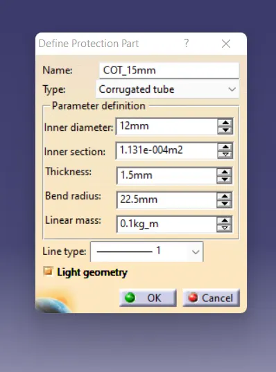
- The bend radius value should always be 1.5 time the value of outer diameter.
- After this the corrugated tube is saved.
Here the corrugated tube created of different diameter and thickness as shown in below table.
|
Name |
ID (mm) |
OD (mm) |
Thickness (mm) |
|
15mm COT |
12 |
15 |
1.5 |
|
20mm COT |
17 |
20 |
1.5 |
|
35mm COT |
32 |
35 |
1.5 |
|
10mm COT |
7 |
10 |
1.5 |
|
5mm COT |
3 |
5 |
1 |
Next step is to add the tube file in the cataloge.
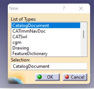
Now click File > New > CatalogueDocument
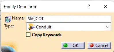
Click add family  and change the name to Slit_Cot and select the type as Conduit.
Save the file.
Now one by one all the tubes are added to the catalogue as below.
- After the completion of creating tube, store device
 option is clicked and the Slit_COT catalogue file created is selected and family is selected as Slit_Cot.
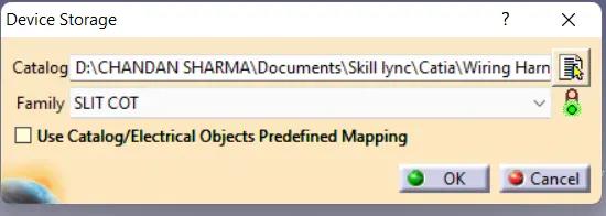
Same procedure is done foe all the corrugated tubes created and the files are saved accordingly.
Conclusion
- All the support to the p clamp is provided.
- All electrical connection is defined to the Back Shell.
- The corrugated tubes are created and saved in the catalogue.
Thank you.