Roof challenge
Aim: To design the roof assembly as per given master section. Calculate the feasibility of roof for the Heat Distortion and the Snow-load conditions. Also, perform the draft analysis on the components of the roof assembly.
What is an automobile roof?
An automobile roof is a BIW sub-assembly which is mounted on top of a car to complete the closed model of a car. The roof also serves its purpose to protect the occupants from sunlight, rain and wind. There are various types of roofs used on different types of vehicles.
- Hard Tops: These are the most common roofs used in the automobile industry which are made of either plastic or metal. Hard tops are classified as A) Detachable Hardtops and B) Retraceable Hard Tops
The detachable hard tops can be removed from the car and stored in the trunk of the car. The Retraceable hard tops retract and fix on the car automatically. - Soft Tops: These types of roofs are used in convertibles. They are made of textile material which include latex, vinyl, PVC.
- Sunroof: The sunroof is an operational type of roof that allows for an opening in the roof of a car. It can allow either light or air or both to enter the car when the sunroof is opened. The sunroof mounting is generally placed at the center of the front and rear seats. The Panoramic Sunroof is an exception which pans from the front of the car all the way to the rear seats.
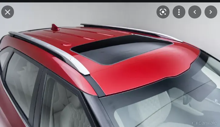
Fig. 1: Roof of a Car including a sunroof and roof rails

Fig. 2: Convertible roof of car
Design of Roof Assembly: The roof Class-A surface was given and the other parts of the roof assembly needed to be designed as per the given master sections. The roof assembly that would be designed needed to adhere to some design criteria as listed below:
- Material Selection: The material for a certain part is selected keeping in mind the tensile strength, bending capacity, static and dynamic loading capacity. The materials used for the roof assembly are listed below
Roof: SP121AQ T0.7
Front Roof Rail: SP783AJQ
Rear Roof Rail: SP783AJQ
Bow Roof : SP121BQ
Center Roof: SP153-980PQ
- Visibility Criteria: The visibility criteria of a driver is one of the most important parameters to be considered while designing a roof. The inclination of the roof near the driver seat should be such that it should not hinder the visibility of the driver. The driver should be able to see clearly even if the driver is tall.
- Head Clearance: This factor is considered for safety of the occupants. The reinforcements should be designed in a way that it provides ample headroom clearance for the occupants in the car and does not collide with the head in case of serious impact while driving.
- Draw ability: The roof assembly and its reinforcements would be manufactured using the deep drawing process. The design should have proper draft to ease the manufacturing process and no sharp edges to reduce the induced stresses during its functioning.
- Reinforcements and their positions: The reinforcements are provided to increase the strength of the roof assembly altogether and hence their positions along the length of the car is important. The reinforcements should be placed such that the roof assembly should pass the heat distortion criteria and the snow load criteria.
Heat Distortion: This determines the temperature the roof structure can withstand. The value obtained from the prediction formula should be less than 2.7 for the roof to pass the test. The calculations are discussed below.
Snow Load Criteria: This factor is taken into consideration for area with high snowfall which then sets on the car roof and applies load. This criteria measures the elasticity of the roof to make sure the roof structure would return to its original position once the snow is removed from top of the car. The calculations are discussed below.
Design of Roof and Reinforcements: The Class-A surface of the roof was provided as shown below:
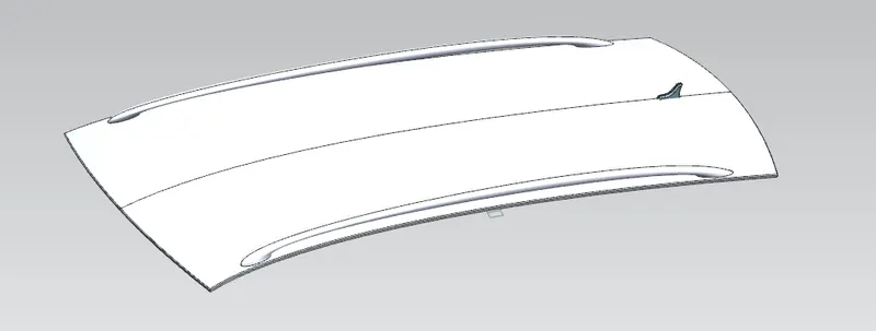
Fig. 3: Class-A roof surface.
- Outer roof and Front Roof Rail: The outer roof and the front roof rail need to be designed to adhere to the visibility criteria. The master section to develop the roof and front roof rail is shown below.
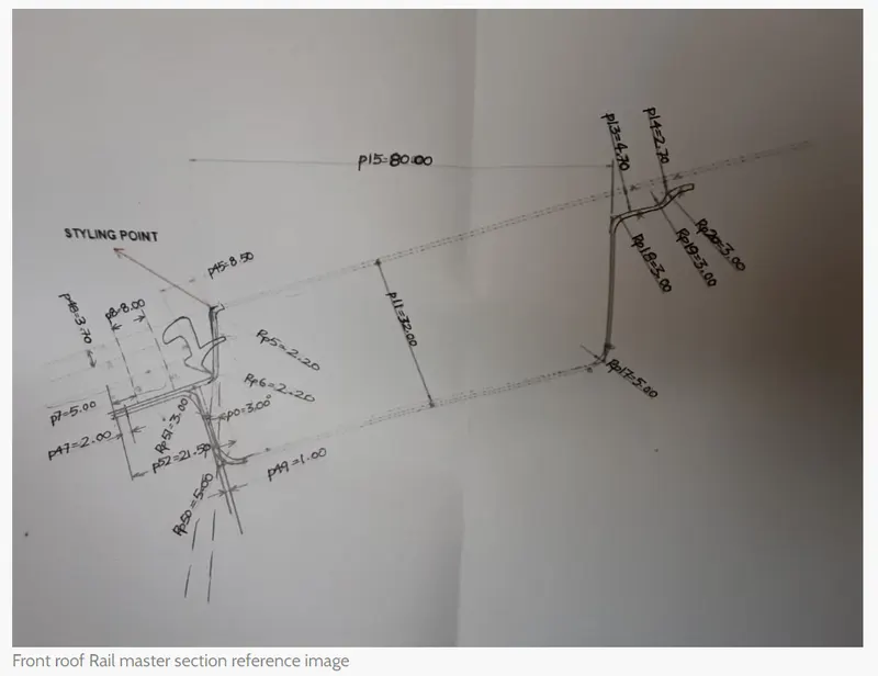
Fig. 4: Master Section to develop outer roof and Front Roof Rail.
The Outer roof rail and the Front Roof Rail are shown below:
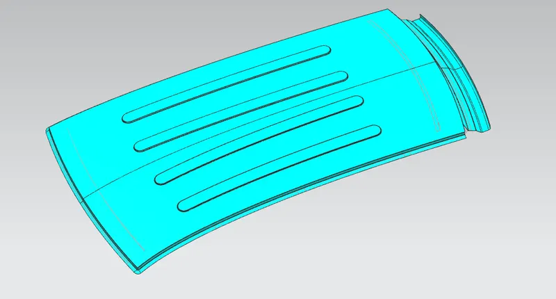
Fig. 5: Isometric View of Outer roof.
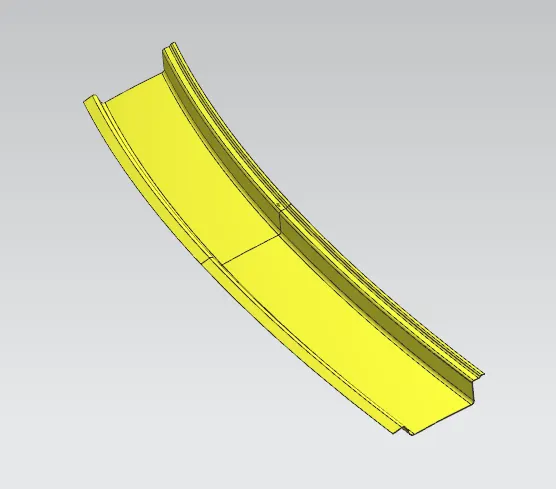
Fig. 6: Isometric view of Front Roof Rail.
- Rear Roof Rail: Similar to the front roof rail, the rear roof rail is also developed using the master section shown below:
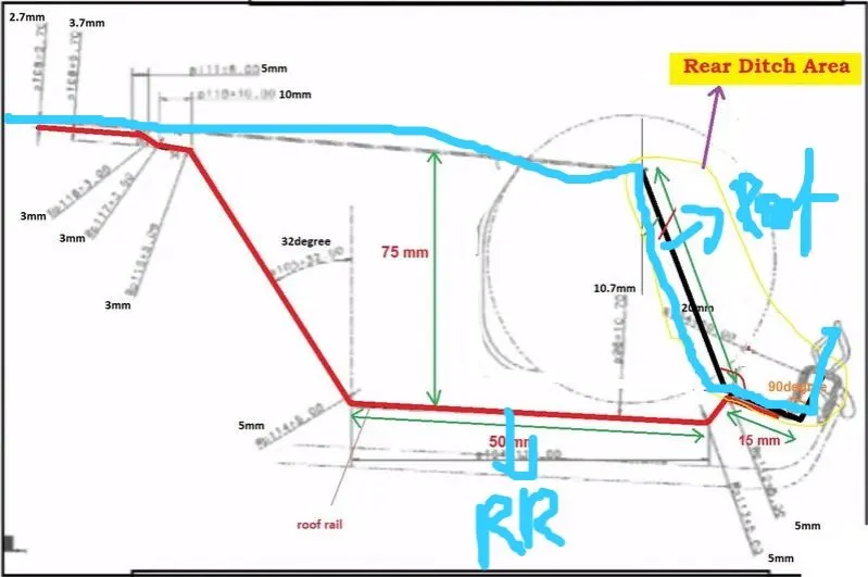
Fig. 7: Master Section to develop rear roof rail.
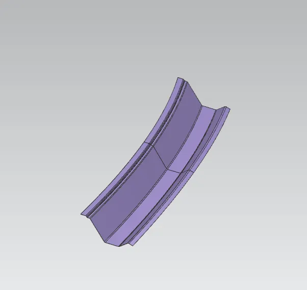
Fig. 8: Isometric view of rear roof rail
- Bow roof rails: The bow roof rails are used to provide structural strength to the roof and they are placed such that they follow the heat distortion criteria. The bow roof rails would be attached to the outer roof using mastics to avoid the spot weld marks on the outer surface. The Bow Roof Rails are shown below:
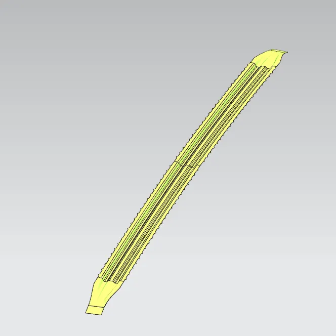
Fig. 9: Isometric view of Bow roof rail
- Central Roof Rail and Reinforcement: The center roof rail provides additional strength in an adverse case of a roll over thus avoiding injury to the occupants. The central roof rail and the reinforcements are welded together and attached to the outer roof using the mastics between outer roof and the reinforcements.
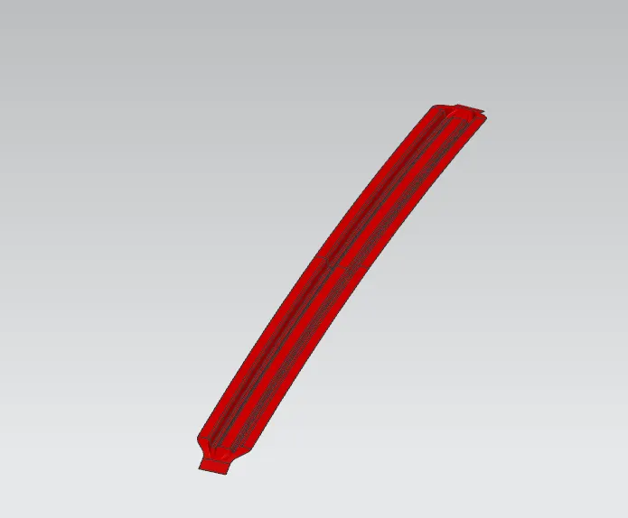
Fig. 10: Isometric View of Central Roof Rail
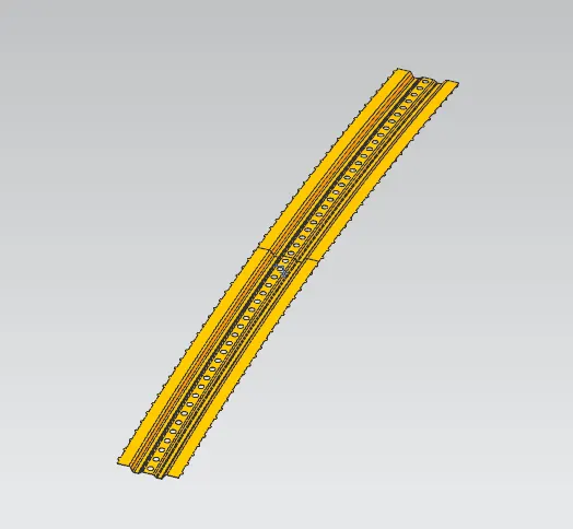
Fig. 11: Isometric View of Central Roof Rail Reinforcement
Heat Distortion Calculations:
`W=[1.73*〖10〗^(-3)*L]+[1.85*〖10〗^(-8)*(R^2/t)]+[1.1*〖10〗^(-3)*I]-2.68`
Judgement condition: W<2.7
Where, L= roof length along X-direction at 0-Y (mm).
R = Roof Curvature
R =, Rx = X curvature & Ry = Y curvature
t= Roof plate thickness
I= Bow roof span
|
Heat Distortion Calculations |
||||||||||
|
Sr.No. |
Region |
L (mm) |
t (mm) |
I |
Rx |
Ry |
R |
R2/t |
W |
Result |
|
1. |
FRR- BR1 |
2200 |
0.75 |
425 |
5739.2 |
2540.6 |
3521.45 |
16534166.9 |
1.89 |
OK |
|
2. |
BR1-CR |
2200 |
0.75 |
412 |
4919.8 |
6408.4 |
5566.2 |
41311506.44 |
2.34 |
OK |
|
3. |
CR-BR2 |
2200 |
0.75 |
530 |
3877.2 |
11099.3 |
5746.8 |
44035776.05 |
2.52 |
OK |
|
4. |
BR2-RRR |
2200 |
0.75 |
225 |
3146.4 |
15486.4 |
5230.11 |
36472983.91 |
2.04 |
OK |
Snow load calculations:
`Q_r= 〖[I〗_y*t^2]/[α*s*(〖(R_x+R_y)/2)〗^2*〖10〗^(-8)]`
Where, `α= M_y*〖L_x〗^2*〖10〗^(-12)` & `M_y=Y*(L_y-Y)`
t = Roof plate thickness [mm]
Ly = Distance between the front and rear roof Rails on the Vehicle along with 0-Y[mm]
Length of Roof panel with the center point between Roof rails Front /Rear as the front and rear reference point.
Lx = Distance between the Left and Right end of the roof on the Roof BOW [mm]
Width of the roof panel exposed on the surface.
Y = Distance from Front Roof Rail to Roof Bow [mm]
s = Distance for which Roof BOW bears divided load [mm]
`s= (L_1+L_2)/2`
Iy = Geometrical moment of inertia of Roof BOW (Y cross-section) [mm4]
Rx = Lateral direction curvature radius of roof panel Y cross-section on Roof BOW [mm]
Roof panel curvature Radius of the Length Lx in Front view
Ry = Longitudinal Direction curvature radius of the Roof panel X cross-section on Roof BOW [mm]
Section Inertia Analysis:
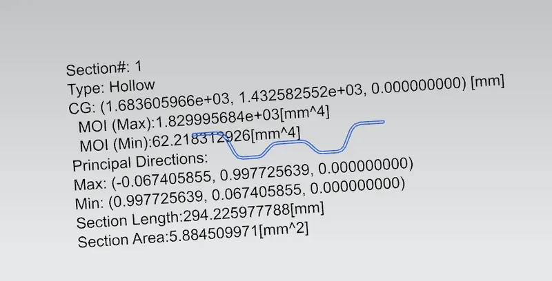
Fig. 12: Section Inertia Analysis of Bow Roof 1
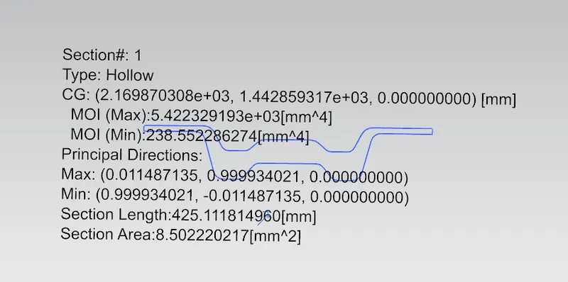
Fig. 13: Section Inertia Analysis of Central Roof Reinforcement
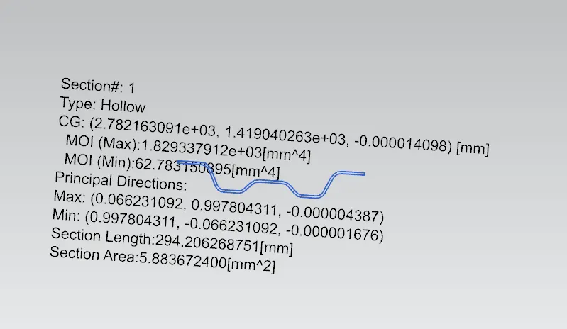
Fig. 14: Section Inertia Analysis of Bow Roof 2
|
Snow Load Calculation |
||||||||||||||
|
Region |
t |
Lx |
Ly |
L1 |
L2 |
RX |
RY |
Y |
s |
Iy |
My |
α |
Qr |
Result |
|
FRR-BR1 |
0.75 |
1185.3 |
2200 |
505.3 |
485.3 |
4532.4 |
2597.8 |
505 |
495 |
62.2 |
856331.9 |
1.2 |
0.46 |
NOT OK |
|
BR1-CR |
0.75 |
1132.3 |
2200 |
485.3 |
612.5 |
3775.5 |
6325.4 |
485 |
548 |
235.5 |
832149.9 |
1.06 |
0.89 |
NOT OK |
|
CR-BR2 |
0.75 |
1103.2 |
2200 |
612.5 |
397.6 |
4314.98 |
11726 |
612 |
505 |
62.7 |
972343.7 |
1.18 |
0.12 |
NOT OK |
|
BR2-RRR |
0.75 |
1088.2 |
2200 |
397.6 |
-- |
3579.1 |
17681 |
398 |
198 |
-- |
716634.2 |
0.84 |
-- |
|
As per the above calculations, the current design of roof assembly does not satisfy the snow load criteria. Following are some suggestions to improve the design. The value of Qr is directly proportional to thickness of material and section inertia.
- The thickness of the sheet metal used to manufacture these components can be increased to improve the snow load criteria.
- Also, the section inertia of the components that support the assembly should be increased to improve the snow load criteria for the roof assembly.
- Addition of more bow roof rails such that the distance between bow roof rails reduces, will improve the strength of roof against snow load.
Draft Analysis Report: The draft analysis of the components of roof assembly are shown below:
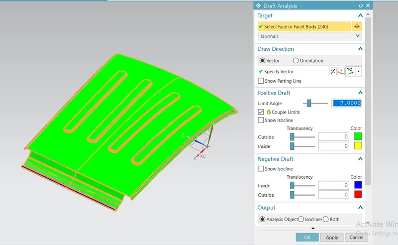
Fig. 15: Draft Analysis of Outer Roof
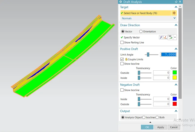
Fig. 16: Draft Analysis of Front roof rail
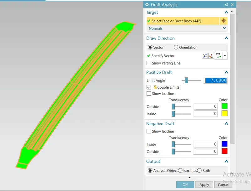
Fig. 17: Draft Analysis of Bow roof 1
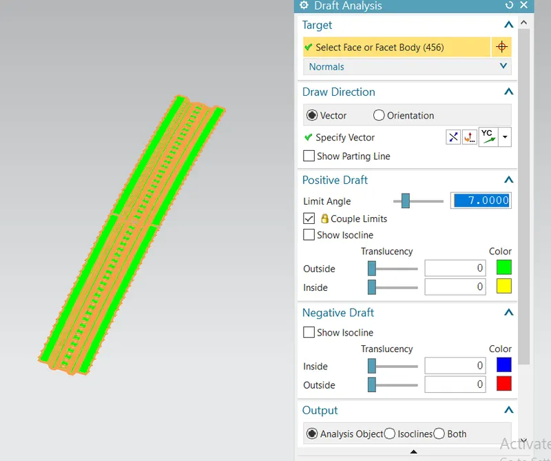
Fig. 18: Draft Analysis of Central Reinforcements
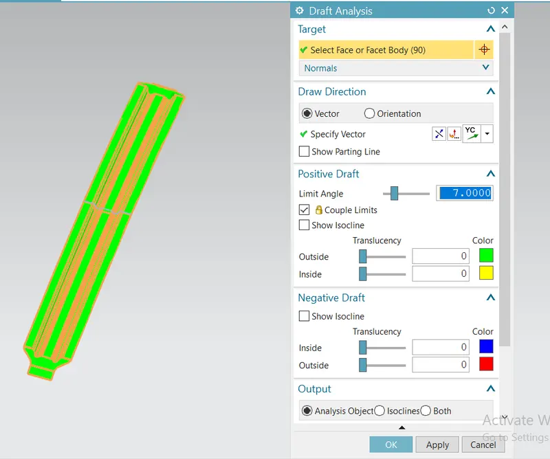
Fig. 19: Draft Analysis of Central Roof Rail
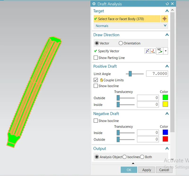
Fig. 20: Draft Analysis of Bow roof 2
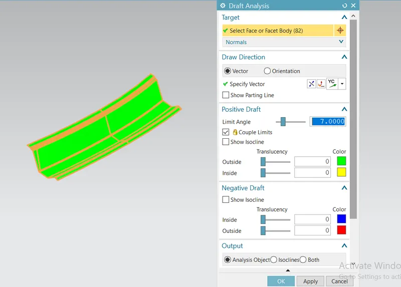
Fig. 21: Draft Analysis of Rear roof rail
The final roof assembly is shown below:
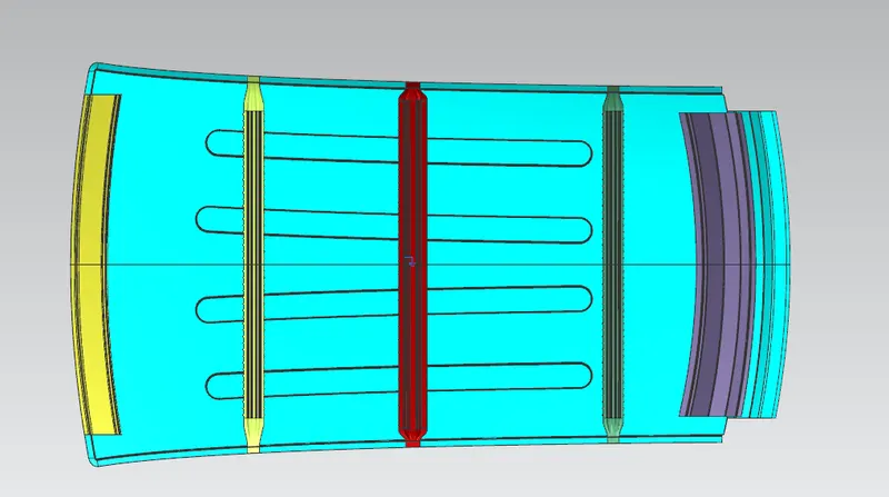
Fig. 22: Front View of final roof assembly
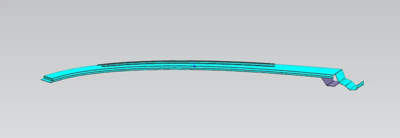
Fig. 23: Top View of final roof assembly
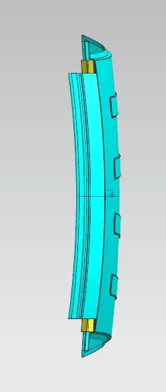
Fig. 24: Right View of final roof assembly
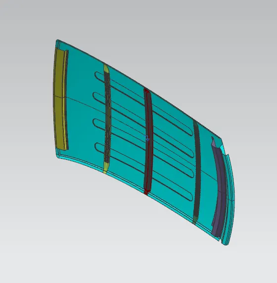
Fig. 25: Isometric View of final roof assembly
Conclusion: The roof assembly was successfully designed according to master section and calculations were performed for heat distortion criteria and snow load criteria. Also, a few ways to improve the performance of the roof against snow load were suggested as above.